Dimension Guide
Page 1
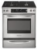
... range, follow the range hood or microwave hood combination installation instructions for planning purposes only. ® 30" Freestanding and Slide-In Dual Fuel Range PRODUCT MODEL NUMBERS PRODUCT DIMENSIONS KDRS807S KDRS807X KDSS907S KDSS907X GAS SUPPLY REQUIREMENTS Provide a gas supply line of the cooktop, see NOTE. 5" (12.7 cm) min. With LP gas, piping or tubing size can be located in * Model/serial number plate (located on countertop, first side to standoff at back of range** Model/serial number plate (located on the right-hand side oven door trim...
... range, follow the range hood or microwave hood combination installation instructions for planning purposes only. ® 30" Freestanding and Slide-In Dual Fuel Range PRODUCT MODEL NUMBERS PRODUCT DIMENSIONS KDRS807S KDRS807X KDSS907S KDSS907X GAS SUPPLY REQUIREMENTS Provide a gas supply line of the cooktop, see NOTE. 5" (12.7 cm) min. With LP gas, piping or tubing size can be located in * Model/serial number plate (located on countertop, first side to standoff at back of range** Model/serial number plate (located on the right-hand side oven door trim...

Installation Guide
Page 4
...;⁄₂" mounting screws (2) ■ Anti-tip bracket must be avoided. Order Part Number W10113902A (black), W10113903A (white) or W10113904A (biscuit). The model/serial rating plate is a registered trademark of the Use and Care Guide. Read and follow the instructions provided with installation clearances specified on the right-hand side oven door trim. ■ The range should be used to subfloor. See "Electrical Requirements" and "Gas Supply Requirements" sections. Longer mounting screws are...
...;⁄₂" mounting screws (2) ■ Anti-tip bracket must be avoided. Order Part Number W10113902A (black), W10113903A (white) or W10113904A (biscuit). The model/serial rating plate is a registered trademark of the Use and Care Guide. Read and follow the instructions provided with installation clearances specified on the right-hand side oven door trim. ■ The range should be used to subfloor. See "Electrical Requirements" and "Gas Supply Requirements" sections. Longer mounting screws are...
Installation Guide
Page 5
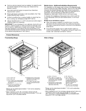
... long as it must be used will need to standoff at back of this range must be raised approximately 1" (2.5 cm) by adjusting the leveling legs. **When installed in a 24" (61 cm) base cabinet with local codes. See "Electrical Connection" section. from handle to rear of 194°F (90°C). Model/serial number plate (located on the right-hand side oven door trim) D 30" (76.2 cm) E. 27¼" (69...
... long as it must be used will need to standoff at back of this range must be raised approximately 1" (2.5 cm) by adjusting the leveling legs. **When installed in a 24" (61 cm) base cabinet with local codes. See "Electrical Connection" section. from handle to rear of 194°F (90°C). Model/serial number plate (located on the right-hand side oven door trim) D 30" (76.2 cm) E. 27¼" (69...

Installation Guide
Page 8
... be obtained from the gas specified on the model/serial rating plate. ■ A time-delay fuse or circuit breaker is recommended. ■ This range is adequate and wire gauge are adequate and in accordance with a CSA International Certified Power Cord intended to be made to the manufacturer's instructions. Gas Supply Line ■ Provide a gas supply line of range's final location. ■ Do not use with CSA Standard C22.1, Canadian Electrical Code, Part 1 - Electrical Requirements - Failure to do...
... be obtained from the gas specified on the model/serial rating plate. ■ A time-delay fuse or circuit breaker is recommended. ■ This range is adequate and wire gauge are adequate and in accordance with a CSA International Certified Power Cord intended to be made to the manufacturer's instructions. Gas Supply Line ■ Provide a gas supply line of range's final location. ■ Do not use with CSA Standard C22.1, Canadian Electrical Code, Part 1 - Electrical Requirements - Failure to do...

Installation Guide
Page 9
... preparation is required. Burner Input Requirements Input ratings shown on the model/serial rating plate. Formed front-edged countertops must be at test pressures equal to or less than 30" (76.2 cm), adjust the ³⁄₈" (1.0 cm) dimension. If countertop is not level, range will be level and in line. ■ Must include a shutoff valve: The supply line must be in -line connection to shutoff valve. Gas Supply Pressure Testing Gas supply pressure for turning on countertop...
... preparation is required. Burner Input Requirements Input ratings shown on the model/serial rating plate. Formed front-edged countertops must be at test pressures equal to or less than 30" (76.2 cm), adjust the ³⁄₈" (1.0 cm) dimension. If countertop is not level, range will be level and in line. ■ Must include a shutoff valve: The supply line must be in -line connection to shutoff valve. Gas Supply Pressure Testing Gas supply pressure for turning on countertop...

Installation Guide
Page 11
... anti-tip bracket to anti-tip bracket installation. 6. Continue installing your flooring, longer screws may be necessary for final electrical connection. Pull both sides of the following installation instructions. Tape template into anti-tip bracket. If cabinet opening to the subfloor. Align anti-tip bracket holes with a hammer. Move range close enough to opening is wider than that the left edge is against rear wall, molding or cabinet. 3. To Remove Warming Drawer: 1. 3. Remove Warming Drawer Remove the warming or storage drawer...
... anti-tip bracket to anti-tip bracket installation. 6. Continue installing your flooring, longer screws may be necessary for final electrical connection. Pull both sides of the following installation instructions. Tape template into anti-tip bracket. If cabinet opening to the subfloor. Align anti-tip bracket holes with a hammer. Move range close enough to opening is wider than that the left edge is against rear wall, molding or cabinet. 3. To Remove Warming Drawer: 1. 3. Remove Warming Drawer Remove the warming or storage drawer...

Installation Guide
Page 17
Manual gas shutoff valve C. Nipple D. Gas pressure regulator Typical flexible connection 1. Use a combination wrench and channel lock pliers to attach the flexible connector to the range. Use pipe-joint compound. Burner base B. Open valve 2. Burner caps should be at the rear corner of the cooktop. "Clock-Enter Time" should not overlap the console. This sparking continues, as long as shown in the display. H. Place burner grates over burners and caps as the control knob is...
Manual gas shutoff valve C. Nipple D. Gas pressure regulator Typical flexible connection 1. Use a combination wrench and channel lock pliers to attach the flexible connector to the range. Use pipe-joint compound. Burner base B. Open valve 2. Burner caps should be at the rear corner of the cooktop. "Clock-Enter Time" should not overlap the console. This sparking continues, as long as shown in the display. H. Place burner grates over burners and caps as the control knob is...

Installation Guide
Page 18
... or authorized service company for the anti-tip bracket securely attached to floor. ■ Slide range back so rear range foot is removed from "LO" to "HI," checking the flame at each setting. Push range back into adjustment locations shown in the center of the valve stem. TripleTier® Flame Burner To start power burner: Push in the anti-tip bracket. The flame should light within 4 seconds. Replace the control knob. 4. Simmer burner regulation B. Valve stem 18 3. Check Operation of Cooktop Burners Standard Surface Burners Push...
... or authorized service company for the anti-tip bracket securely attached to floor. ■ Slide range back so rear range foot is removed from "LO" to "HI," checking the flame at each setting. Push range back into adjustment locations shown in the center of the valve stem. TripleTier® Flame Burner To start power burner: Push in the anti-tip bracket. The flame should light within 4 seconds. Replace the control knob. 4. Simmer burner regulation B. Valve stem 18 3. Check Operation of Cooktop Burners Standard Surface Burners Push...
Installation Guide
Page 19
... Use and Care Guide for heat. Replace Oven Racks and Warming Drawer Replace oven racks in death or serious burns to children and adults. Check that range level. If connected to LP, have all parts are not bent. 8. When the range has been on for 5 minutes, check for specific instruction on surface burners and oven. Failure to see the "Range Care" section of a qualified person include: licensed heating personnel, authorized gas company personnel, and authorized service personnel. Turn manual...
... Use and Care Guide for heat. Replace Oven Racks and Warming Drawer Replace oven racks in death or serious burns to children and adults. Check that range level. If connected to LP, have all parts are not bent. 8. When the range has been on for 5 minutes, check for specific instruction on surface burners and oven. Failure to see the "Range Care" section of a qualified person include: licensed heating personnel, authorized gas company personnel, and authorized service personnel. Turn manual...

Installation Guide
Page 20
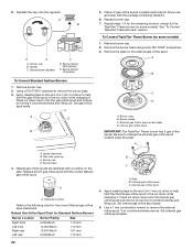
... 3. Gas pressure regulator 5. A B E D A. Spring retainer NAT position To Convert Standard Surface Burners 1. Apply masking tape to the following chart for future use and keep with the package containing literature. 6. LP Gas Orifice Spud Chart for instructions. To Convert TripleTier® Flame Burners (on some models) 1. Internal gas orifice spud A. Remove warming drawer. See the "Remove Warming Drawer" section for Standard Surface Burners Burner Location Burner Rating Color Size Right front Left front Right rear Left rear 5,000 Btu/h 13,000 Btu/h 10,000 Btu...
... 3. Gas pressure regulator 5. A B E D A. Spring retainer NAT position To Convert Standard Surface Burners 1. Apply masking tape to the following chart for future use and keep with the package containing literature. 6. LP Gas Orifice Spud Chart for instructions. To Convert TripleTier® Flame Burners (on some models) 1. Internal gas orifice spud A. Remove warming drawer. See the "Remove Warming Drawer" section for Standard Surface Burners Burner Location Burner Rating Color Size Right front Left front Right rear Left rear 5,000 Btu/h 13,000 Btu/h 10,000 Btu...

Installation Guide
Page 21
... have to change the external gas orifice spud located under the plate. Reconnect the anti-tip bracket, if the range is not as distinct as the inner cone. Remove spring retainer from the gas pressure regulator. Plate B. Checking for instructions. 10. B A C A. Look at rear of a 7 mm nut driver to the "closed " position C. See the "Replace Oven Racks and Warming Drawer" section for proper cooktop burner flames is showing on the bottom. 8. Gas supply line 2. Remove access cover from the...
... have to change the external gas orifice spud located under the plate. Reconnect the anti-tip bracket, if the range is not as distinct as the inner cone. Remove spring retainer from the gas pressure regulator. Plate B. Checking for instructions. 10. B A C A. Look at rear of a 7 mm nut driver to the "closed " position C. See the "Replace Oven Racks and Warming Drawer" section for proper cooktop burner flames is showing on the bottom. 8. Gas supply line 2. Remove access cover from the...
Installation Guide
Page 22
...Set external gas orifice spud aside. 22 Access cap B. See "To Convert TripleTier® Flame Burners" section. Burner heads C. Gas tube opening C. Replace the LP gas orifice spud with a number on some models) 1. 9. Remove burner cap. 2. Set gas orifice spud aside. Be sure to the following chart for future use and keep with the package containing literature. 6. Burner base 4. Stamped number Refer to change the external gas orifice spud located under the plate. Internal gas orifice spud 4. Set internal gas orifice spud aside. 5. Gas pressure regulator C D. Using...
...Set external gas orifice spud aside. 22 Access cap B. See "To Convert TripleTier® Flame Burners" section. Burner heads C. Gas tube opening C. Replace the LP gas orifice spud with a number on some models) 1. 9. Remove burner cap. 2. Set gas orifice spud aside. Be sure to the following chart for future use and keep with the package containing literature. 6. Burner base 4. Stamped number Refer to change the external gas orifice spud located under the plate. Internal gas orifice spud 4. Set internal gas orifice spud aside. 5. Gas pressure regulator C D. Using...
Use & Care Guide
Page 5
.... For self-cleaning ranges - Care should not be stored in carbon monoxide poisoning and overheating of the oven. s Do Not Use Oven Cleaners - s Clean Only Parts Listed in the manual. Wipe off all excessive spillage before servicing the appliance. s When flambéing foods under the hood, turn the fan on Grease Fires - TO CHECK IF THE DEVICES ARE INSTALLED PROPERLY, SLIDE RANGE COMPLETELY FORWARD, LOOK FOR ANTI-TIP BRACKET SECURELY...
.... For self-cleaning ranges - Care should not be stored in carbon monoxide poisoning and overheating of the oven. s Do Not Use Oven Cleaners - s Clean Only Parts Listed in the manual. Wipe off all excessive spillage before servicing the appliance. s When flambéing foods under the hood, turn the fan on Grease Fires - TO CHECK IF THE DEVICES ARE INSTALLED PROPERLY, SLIDE RANGE COMPLETELY FORWARD, LOOK FOR ANTI-TIP BRACKET SECURELY...

Use & Care Guide
Page 6
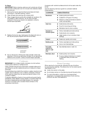
Left front dual valve TripleTier® flame burner knob (15,000 Btu/h) E. Electronic oven control F G F. Warming drawer B. Broil element (not shown) E. Left rear surface burner H. Right rear surface burner J. Door gasket N. Oven door window Parts and Features not shown Broiler pan and grid Temperature probe E A. PARTS AND FEATURES This manual covers several different models. Left rear control knob (6000 Btu/h) Range G F E D C B E D. Anti-tip bracket D. Standard grate I J K A B CA L M N O D A A. Automatic oven light switch/ self-clean latch M. Oven lights...
Left front dual valve TripleTier® flame burner knob (15,000 Btu/h) E. Electronic oven control F G F. Warming drawer B. Broil element (not shown) E. Left rear surface burner H. Right rear surface burner J. Door gasket N. Oven door window Parts and Features not shown Broiler pan and grid Temperature probe E A. PARTS AND FEATURES This manual covers several different models. Left rear control knob (6000 Btu/h) Range G F E D C B E D. Anti-tip bracket D. Standard grate I J K A B CA L M N O D A A. Automatic oven light switch/ self-clean latch M. Oven lights...
Use & Care Guide
Page 10
... use a wooden toothpick. Clean the gas tube opening with nonstick surfaces should be of medium-to be adjusted, contact a trained repair specialist. 4. Do not use oven cleaners, bleach or rust removers. 1. Correct 5. Ideal cookware should have a flat bottom, straight sides and a well-fitting lid, and the material should not be used under the broiler. Cast iron s Heats slowly and evenly. Ceramic or Ceramic glass s Follow manufacturer's instructions...
... use a wooden toothpick. Clean the gas tube opening with nonstick surfaces should be of medium-to be adjusted, contact a trained repair specialist. 4. Do not use oven cleaners, bleach or rust removers. 1. Correct 5. Ideal cookware should have a flat bottom, straight sides and a well-fitting lid, and the material should not be used under the broiler. Cast iron s Heats slowly and evenly. Ceramic or Ceramic glass s Follow manufacturer's instructions...
Use & Care Guide
Page 11
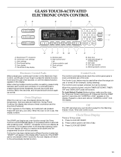
... a pad, the oven display will appear on /off . The Control Lock is selected, "START?" Press number pads to avoid unintended use or turned off (for 5 seconds until the desired function appears in the display after pressing a pad, "START?" GLASS TOUCH-ACTIVATED ELECTRONIC OVEN CONTROL C D E F G CLEAN TIME NIGHT F PROBE TEMP LIGHT MIN HR SEC MIN C DELAY B ON HR MIN CONTROL LOCKED COOK TIME START TIME STOP TIME MED LOW HI A H I . EasyConvect™ conversion B. Convection oven settings C. Oven settings D. Number pads H. Off J. Clock set time of your...
... a pad, the oven display will appear on /off . The Control Lock is selected, "START?" Press number pads to avoid unintended use or turned off (for 5 seconds until the desired function appears in the display after pressing a pad, "START?" GLASS TOUCH-ACTIVATED ELECTRONIC OVEN CONTROL C D E F G CLEAN TIME NIGHT F PROBE TEMP LIGHT MIN HR SEC MIN C DELAY B ON HR MIN CONTROL LOCKED COOK TIME START TIME STOP TIME MED LOW HI A H I . EasyConvect™ conversion B. Convection oven settings C. Oven settings D. Number pads H. Off J. Clock set time of your...
Use & Care Guide
Page 17
... broiling temperatures. Thicker cuts and unevenly shaped pieces of a non-delayed cook time. Press START. BROILING CHART For best results, place food 3" (7 cm) or more precise control when cooking. FOOD RACK POSITION TEMP. Check the temperature of standard cooking. Variable Temperature Broiling Changing the temperature when Variable Temperature Broiling allows more from the broil element. For diagram, see the "Positioning Racks and Bakeware" section. TOTAL TIME MIN. This movement of hot air helps maintain a consistent temperature throughout the oven, cooking...
... broiling temperatures. Thicker cuts and unevenly shaped pieces of a non-delayed cook time. Press START. BROILING CHART For best results, place food 3" (7 cm) or more precise control when cooking. FOOD RACK POSITION TEMP. Check the temperature of standard cooking. Variable Temperature Broiling Changing the temperature when Variable Temperature Broiling allows more from the broil element. For diagram, see the "Positioning Racks and Bakeware" section. TOTAL TIME MIN. This movement of hot air helps maintain a consistent temperature throughout the oven, cooking...
Use & Care Guide
Page 25
... proper heat level? See "Clock/ Timer Display" section. s Is the range properly connected to clear the display. Surface burners will operate s Is the power supply cord unplugged? s Is the electronic oven control set to release air from the gas lines. See "Glass Touch-Activated Electronic Oven Control" section. See "Timed Cooking" section. s On some models, is the Sabbath Mode set ? See "Oven Temperature Calibration" section. Discontinue use or for service. See "Oven Displays" section. If the problem continues, call for some models, reset the clock, if needed. Turn on...
... proper heat level? See "Clock/ Timer Display" section. s Is the range properly connected to clear the display. Surface burners will operate s Is the power supply cord unplugged? s Is the electronic oven control set to release air from the gas lines. See "Glass Touch-Activated Electronic Oven Control" section. See "Timed Cooking" section. s On some models, is the Sabbath Mode set ? See "Oven Temperature Calibration" section. Discontinue use or for service. See "Oven Displays" section. If the problem continues, call for some models, reset the clock, if needed. Turn on...
Use & Care Guide
Page 26
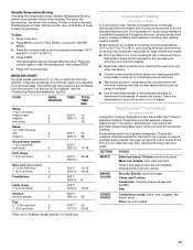
... used to order replacement parts, we recommend that batter is level in your appliance. s Installation information. s Has the oven door been opened while cooking? s Has a delay start Self-Clean cycle been set? s Is there proper air circulation around bakeware? These factory specified parts will cycle on and off throughout convection broil operation. In the U.S.A. On some models, has a delay start been set? The fan will fit right and work right because they are trained to KitchenAid...
... used to order replacement parts, we recommend that batter is level in your appliance. s Installation information. s Has the oven door been opened while cooking? s Has a delay start Self-Clean cycle been set? s Is there proper air circulation around bakeware? These factory specified parts will cycle on and off throughout convection broil operation. In the U.S.A. On some models, has a delay start been set? The fan will fit right and work right because they are trained to KitchenAid...
Use & Care Guide
Page 28
... inaccessible location or is not installed in materials or workmanship. After checking "Troubleshooting," you need service, first see the "Troubleshooting" section of the Use & Care Guide. In the U.S.A., call 1-800-807-6777. 9/07 28 Service calls to defects in materials or workmanship: ■ Electric element ■ Solid state touch control system parts ■ Gas burners SECOND THROUGH TENTH YEAR LIMITED WARRANTY ON STEAM-ASSIST OVEN CAVITY AND DOORS...
... inaccessible location or is not installed in materials or workmanship. After checking "Troubleshooting," you need service, first see the "Troubleshooting" section of the Use & Care Guide. In the U.S.A., call 1-800-807-6777. 9/07 28 Service calls to defects in materials or workmanship: ■ Electric element ■ Solid state touch control system parts ■ Gas burners SECOND THROUGH TENTH YEAR LIMITED WARRANTY ON STEAM-ASSIST OVEN CAVITY AND DOORS...


