
Installation Manual
Page 1
KVT-719DVD KVT-739DVD MONITOR WITH DVD RECEIVER INSTALLATION MANUAL MONITOR CON RECEPTOR DVD MANUAL DE INSTALACIÓN © B54-4513-00/00 (KV/RV)
KVT-719DVD KVT-739DVD MONITOR WITH DVD RECEIVER INSTALLATION MANUAL MONITOR CON RECEPTOR DVD MANUAL DE INSTALACIÓN © B54-4513-00/00 (KV/RV)
Installation Manual
Page 3
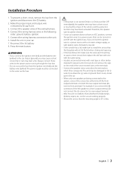
..., connect the connectors either to both the front output terminals or to both the rear output terminals (do not remove the caps on and off with battery wires, the battery may be turned on the ends of the left speaker to which they correspond. Installation Procedure 1. Make the proper input and output wireɹ connections for each unit. 3. For example, if you may start a fire. battery. 8. Connect the wiring harness wires in turn may...
..., connect the connectors either to both the front output terminals or to both the rear output terminals (do not remove the caps on and off with battery wires, the battery may be turned on the ends of the left speaker to which they correspond. Installation Procedure 1. Make the proper input and output wireɹ connections for each unit. 3. For example, if you may start a fire. battery. 8. Connect the wiring harness wires in turn may...
Installation Manual
Page 4
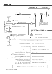
... lamp harness Reverse sensor wire (Purple/White) To car light control switch Dimmer control wire (Orange/White) To steering remote Connect to the terminal that is fixed with a chassis using the supplied relay connector. To connect the Kenwood navigation system, consult your navigation manual. Depending on what antenna you are made, do not let the cable come out from the tab. 4 | KVT-719DVD/KVT-739DVD Steering remote control input (Light Blue/Yellow) Mute wire (Brown) Motor antenna control wire (Blue) Power control wire (Blue/White) External amplifier control wire...
... lamp harness Reverse sensor wire (Purple/White) To car light control switch Dimmer control wire (Orange/White) To steering remote Connect to the terminal that is fixed with a chassis using the supplied relay connector. To connect the Kenwood navigation system, consult your navigation manual. Depending on what antenna you are made, do not let the cable come out from the tab. 4 | KVT-719DVD/KVT-739DVD Steering remote control input (Light Blue/Yellow) Mute wire (Brown) Motor antenna control wire (Blue) Power control wire (Blue/White) External amplifier control wire...
Installation Manual
Page 5
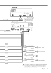
... in turn may start a fire. CONT EXT. English | 5 CONT FRONT L FRONT R White/Black White + Gray/Black + Gray Green/Black + Green Purple/Black Purple + To front left speaker To front right speaker To rear left speaker To rear right speaker REAR L REAR R If you connect the ignition wire (red) and the battery wire (yellow) to the power source running through the fuse box. Receiver unit Accessory 3 Receiver unit Accessory @ The cable (Accessory...
... in turn may start a fire. CONT EXT. English | 5 CONT FRONT L FRONT R White/Black White + Gray/Black + Gray Green/Black + Green Purple/Black Purple + To front left speaker To front right speaker To rear left speaker To rear right speaker REAR L REAR R If you connect the ignition wire (red) and the battery wire (yellow) to the power source running through the fuse box. Receiver unit Accessory 3 Receiver unit Accessory @ The cable (Accessory...
Installation Manual
Page 6
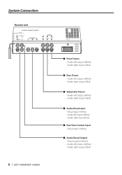
System Connection Receiver unit 6 | KVT-719DVD/KVT-739DVD ■ Front Preout • Audio left output (White) • Audio right output (Red) ■ Rear Preout • Audio left output (White) • Audio right output (Red) ■ Subwoofer Preout • Audio left output (White) • Audio right output (Red) ■ Audio/Visual input • Visual input (Yellow) • Audio left input (White) • Audio right input (Red) ■ Rear View Camera Input • Visual input (Yellow) ■ Audio/Visual Output • Visual output (Yellow) • Audio left output (...
System Connection Receiver unit 6 | KVT-719DVD/KVT-739DVD ■ Front Preout • Audio left output (White) • Audio right output (Red) ■ Rear Preout • Audio left output (White) • Audio right output (Red) ■ Subwoofer Preout • Audio left output (White) • Audio right output (Red) ■ Audio/Visual input • Visual input (Yellow) • Audio left input (White) • Audio right input (Red) ■ Rear View Camera Input • Visual input (Yellow) ■ Audio/Visual Output • Visual output (Yellow) • Audio left output (...
Installation Manual
Page 7
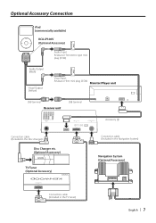
... Connection iPod AUDIO IN iPod (commercially available) KCA-iP300V (Optional Accessory) Audio Input Resistance-free stereo type mini plug (3.5Ф) iPod VIDEO IN Audio Output (Black) Visual Output (Yellow) Visual Input Resistance-free mini plug (3.5Ф) Monitor/Player unit USB terminal Receiver unit USB terminal Accessory 3 Connection cable (Included in the Disc changer) Disc Changer etc. (Optional Accessory) TV Tuner (Optional Accessory) Connection cable (Included in the Navigation System) Navigation System (Optional Accessory) TV ANTENNA INPUT TO MONITOR UNIT Connection...
... Connection iPod AUDIO IN iPod (commercially available) KCA-iP300V (Optional Accessory) Audio Input Resistance-free stereo type mini plug (3.5Ф) iPod VIDEO IN Audio Output (Black) Visual Output (Yellow) Visual Input Resistance-free mini plug (3.5Ф) Monitor/Player unit USB terminal Receiver unit USB terminal Accessory 3 Connection cable (Included in the Disc changer) Disc Changer etc. (Optional Accessory) TV Tuner (Optional Accessory) Connection cable (Included in the Navigation System) Navigation System (Optional Accessory) TV ANTENNA INPUT TO MONITOR UNIT Connection...
Installation Manual
Page 8
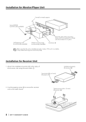
... or metal support Self-tapping screw (commercially available) Metal mounting strap (commercially available) Bend the tabs of the receiver unit using the sems bolts 7. Accessory 5 Make sure that the unit is unstable, it in place. Tapping screw (ø4 × 16 mm) (Accessory 8) 8 | KVT-719DVD/KVT-739DVD If the unit is installed securely in place. Attach the installation brackets 9 to the audio board. Use the tapping...
... or metal support Self-tapping screw (commercially available) Metal mounting strap (commercially available) Bend the tabs of the receiver unit using the sems bolts 7. Accessory 5 Make sure that the unit is unstable, it in place. Tapping screw (ø4 × 16 mm) (Accessory 8) 8 | KVT-719DVD/KVT-739DVD If the unit is installed securely in place. Attach the installation brackets 9 to the audio board. Use the tapping...
Installation Manual
Page 9
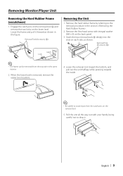
... on the lower level. Removal Tool (Accessory 6) Removing the Unit 1. Removal Tool (Accessory 6) Catch Lock ⁄ • The frame can be removed from the catch pins on the back panel. 3. Lower the frame and pull it . Engage the catch pins on the removal tool 6 and remove the two locks on each side, as shown in the section . 2. Remove the Hex-head screw with...
... on the lower level. Removal Tool (Accessory 6) Removing the Unit 1. Removal Tool (Accessory 6) Catch Lock ⁄ • The frame can be removed from the catch pins on the back panel. 3. Lower the frame and pull it . Engage the catch pins on the removal tool 6 and remove the two locks on each side, as shown in the section . 2. Remove the Hex-head screw with...
Installation Manual
Page 10
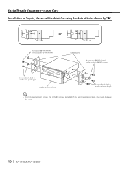
If you could damage the unit. 10 | KVT-719DVD/KVT-739DVD Use only the screws provided. Installing in Japanese-made Cars Installation on Toyota, Nissan or Mitsubishi Car using Brackets at Holes shown by "●" or Accessory 0 (M5x6mm) or Accessory ! (M5x7mm) Car Bracket Accessory 0 (M5x6mm) or Accessory ! (M5x7mm) Screws (included in audio unit package) Audio unit or others Screws (included in audio unit package) ⁄ • Do not use the wrong screws, you use your own screws.
If you could damage the unit. 10 | KVT-719DVD/KVT-739DVD Use only the screws provided. Installing in Japanese-made Cars Installation on Toyota, Nissan or Mitsubishi Car using Brackets at Holes shown by "●" or Accessory 0 (M5x6mm) or Accessory ! (M5x7mm) Car Bracket Accessory 0 (M5x6mm) or Accessory ! (M5x7mm) Screws (included in audio unit package) Audio unit or others Screws (included in audio unit package) ⁄ • Do not use the wrong screws, you use your own screws.
Installation Manual
Page 11
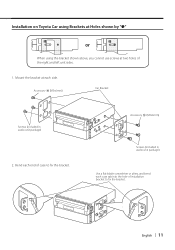
English | 11 Installation on Toyota Car using Brackets at Holes shown by "●" or When using the bracket shown above, you cannot use screws at each side. Bend each case tab into the hole of the right and left unit sides. 1. Accessory 0 (M5x6mm) Car Bracket Screws (included in audio unit package) Use a flat-blade screwdriver or pliers, and bend each end of case to fix the bracket. Accessory 0 (M5x6mm) Screws (included in audio unit package) 2. Mount the bracket at two holes of installation bracket to fix the bracket.
English | 11 Installation on Toyota Car using Brackets at Holes shown by "●" or When using the bracket shown above, you cannot use screws at each side. Bend each case tab into the hole of the right and left unit sides. 1. Accessory 0 (M5x6mm) Car Bracket Screws (included in audio unit package) Use a flat-blade screwdriver or pliers, and bend each end of case to fix the bracket. Accessory 0 (M5x6mm) Screws (included in audio unit package) 2. Mount the bracket at two holes of installation bracket to fix the bracket.


