Instruction Manual
Page 1
... the unit, in the space provided below. Model KDC-205, KDC-205CR, KDC-105 Serial number © B64-2670-00 / 00 (KN) Familiarity with installation and operation procedures will help you call upon your KENWOOD dealer for information or service on the warranty card, and in the spaces designated on the product. Refer to read through this instruction manual. KDC-205 KDC-205CR KDC-105 CD-RECEIVER INSTRUCTION MANUAL AMPLI-TUNER-LECTEUR DE CD MODE...
... the unit, in the space provided below. Model KDC-205, KDC-205CR, KDC-105 Serial number © B64-2670-00 / 00 (KN) Familiarity with installation and operation procedures will help you call upon your KENWOOD dealer for information or service on the warranty card, and in the spaces designated on the product. Refer to read through this instruction manual. KDC-205 KDC-205CR KDC-105 CD-RECEIVER INSTRUCTION MANUAL AMPLI-TUNER-LECTEUR DE CD MODE...
Instruction Manual
Page 2
... 3 About CDs 5 General features 6 Power Selecting the Source Volume Attenuator Loudness System Q Audio Control Speaker Setting Clock Display Adjusting Clock DSI (Disabled System Indicator) Theft Deterrent Faceplate Tuner features 9 Tuning Mode Tuning Station Preset Memory Auto Memory Entry Preset Tuning CRSC (Clean Reception System Circuit) CD player features 11 Playing CD Fast Forwarding and Reversing Track Search Track Repeat Track Scan Random Play Accessories 13 Installation Procedure 13 Connecting Wires to Terminals 14 Installation 15 Troubleshooting Guide 17 Specifications 19...
... 3 About CDs 5 General features 6 Power Selecting the Source Volume Attenuator Loudness System Q Audio Control Speaker Setting Clock Display Adjusting Clock DSI (Disabled System Indicator) Theft Deterrent Faceplate Tuner features 9 Tuning Mode Tuning Station Preset Memory Auto Memory Entry Preset Tuning CRSC (Clean Reception System Circuit) CD player features 11 Playing CD Fast Forwarding and Reversing Track Search Track Repeat Track Scan Random Play Accessories 13 Installation Procedure 13 Connecting Wires to Terminals 14 Installation 15 Troubleshooting Guide 17 Specifications 19...
Instruction Manual
Page 3
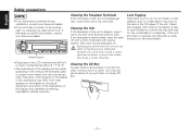
... malfunction. • To prevent a short circuit when replacing a fuse, first disconnect the wiring harness. • Do not place any metallic objects (such as it to direct sunlight, excessive heat or humidity. CDs in the CD slot If you could damage the unit. Do Not Load 3-in. Using a fuse with its adapter into the unit, the adapter might separate from the LCD contacts your...
... malfunction. • To prevent a short circuit when replacing a fuse, first disconnect the wiring harness. • Do not place any metallic objects (such as it to direct sunlight, excessive heat or humidity. CDs in the CD slot If you could damage the unit. Do Not Load 3-in. Using a fuse with its adapter into the unit, the adapter might separate from the LCD contacts your...
Instruction Manual
Page 4
... play. Called lens fogging, CDs may affect its mechanical parts. Wiping the faceplate with a dry, soft cloth. If that does not solve the problem, consult your Kenwood dealer. Applying spray cleaner directly to evaporate. In such a situation, remove the disc and wait for the condensation to the unit may be working right, try pressing the reset button first. If the unit still does not operate...
... play. Called lens fogging, CDs may affect its mechanical parts. Wiping the faceplate with a dry, soft cloth. If that does not solve the problem, consult your Kenwood dealer. Applying spray cleaner directly to evaporate. In such a situation, remove the disc and wait for the condensation to the unit may be working right, try pressing the reset button first. If the unit still does not operate...
Instruction Manual
Page 5
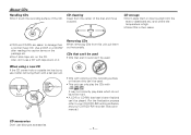
...; Don't stick tape etc. Use a CD-R or a CD-RW after reading the caution items on it after removing them out horizontally. Also, don't use disc type accessories. -5- on the recording surface or that are easier to your CD-R/CD-RW writing software, and your CD-R/CD-RW recorder instruction manual.) CD accessories Don't use a CD with coloring on the CD. CD cleaning Clean from this unit pull them with .
...; Don't stick tape etc. Use a CD-R or a CD-RW after reading the caution items on it after removing them out horizontally. Also, don't use disc type accessories. -5- on the recording surface or that are easier to your CD-R/CD-RW writing software, and your CD-R/CD-RW recorder instruction manual.) CD accessories Don't use a CD with coloring on the CD. CD cleaning Clean from this unit pull them with .
Instruction Manual
Page 6
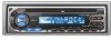
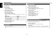
.../ ADJ Selecting the Source Press the [SRC] button. When it's ON, the "ATT" indicator blinks. -6- Each time the button is pressed the Attenuator turns ON or OFF. Decreasing Volume Press the [d] button. Source required Tuner CD Standby (Illumination only mode) Display "TUnE" "CD" "STBY" SYSTEM Q indicator Clock display LOUD indicator Volume Increasing Volume Press the [u] button. Turning OFF the Power Press the [SRC] button for at least 1 second. English General features Release button (KDC-205/KDC-205CR only...
.../ ADJ Selecting the Source Press the [SRC] button. When it's ON, the "ATT" indicator blinks. -6- Each time the button is pressed the Attenuator turns ON or OFF. Decreasing Volume Press the [d] button. Source required Tuner CD Standby (Illumination only mode) Display "TUnE" "CD" "STBY" SYSTEM Q indicator Clock display LOUD indicator Volume Increasing Volume Press the [u] button. Turning OFF the Power Press the [SRC] button for at least 1 second. English General features Release button (KDC-205/KDC-205CR only...
Instruction Manual
Page 7
...;] button. Front 15 5 Exit Audio Control mode Press the [AUD] button. -7- Right 15 Rear 15 - Each time the button is pressed the items that can recall the best sound setting preset for different types of the music. 1 Select the source to set in audio control replace the System Q values. Sound setting Display Flat Rock Top 40 Pops Jazz Easy "FLAT" "ROCK" "TP40" "POPS" "JAZZ" "EASY" • Each setting value is changed with the Speaker setting...
...;] button. Front 15 5 Exit Audio Control mode Press the [AUD] button. -7- Right 15 Rear 15 - Each time the button is pressed the items that can recall the best sound setting preset for different types of the music. 1 Select the source to set in audio control replace the System Q values. Sound setting Display Flat Rock Top 40 Pops Jazz Easy "FLAT" "ROCK" "TP40" "POPS" "JAZZ" "EASY" • Each setting value is changed with the Speaker setting...
Instruction Manual
Page 8
..." display. 2 Enter Speaker Setting mode Press the [Q] button. 3 Select the Speaker type Press the [4] or [¢] button. speaker For 5 & 4 in . Each time the step 1 and 2 operation is optimal when setting the speaker type. 1 Enter Standby Press the [SRC] button. The clock display blinks. 3 Adjust the hours Press the [FM] or [AM] button. Function of the KDC-205/KDC-205CR DSI (Disabled System Indicator) A red indicator will blink on the unit after the faceplate is removed...
..." display. 2 Enter Speaker Setting mode Press the [Q] button. 3 Select the Speaker type Press the [4] or [¢] button. speaker For 5 & 4 in . Each time the step 1 and 2 operation is optimal when setting the speaker type. 1 Enter Standby Press the [SRC] button. The clock display blinks. 3 Adjust the hours Press the [FM] or [AM] button. Function of the KDC-205/KDC-205CR DSI (Disabled System Indicator) A red indicator will blink on the unit after the faceplate is removed...
Instruction Manual
Page 9
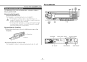
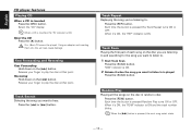
... you , helping to direct sunlight or excessive heat or humidity. Reattaching the Faceplate 1 Align the projections on the unit with too much dust or the possibility of water splashing. Removing the Faceplate Press the Release button. Tuner features LOUD AME AUTO AUD OFF AUTO/ SRC AME FM/ 4 AM CRSC ¢ CRSC SCAN RDM REP 1 - 6 CLK ADJ Band display Preset station number Frequency display 2 Push the faceplate in...
... you , helping to direct sunlight or excessive heat or humidity. Reattaching the Faceplate 1 Align the projections on the unit with too much dust or the possibility of water splashing. Removing the Faceplate Press the Release button. Tuner features LOUD AME AUTO AUD OFF AUTO/ SRC AME FM/ 4 AM CRSC ¢ CRSC SCAN RDM REP 1 - 6 CLK ADJ Band display Preset station number Frequency display 2 Push the faceplate in...
Instruction Manual
Page 10
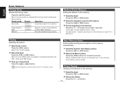
...] button for a station. Press the [AUTO] button. Automatic search for at least 2 seconds. The preset number display blinks 1 time. Select the "TUnE" display. 2 Select the band Press the [FM] or [AM] button. Each time the [FM] button is pressed the Tuning mode switches as shown below. Auto Memory Entry Putting stations with good reception in the memory Press the [1] - [6] button for at least 2 seconds. Preset Tuning Calling up the stations in the memory Auto Memory Entry closes. Tuning Selecting the station. 1 Select tuner source Press...
...] button for a station. Press the [AUTO] button. Automatic search for at least 2 seconds. The preset number display blinks 1 time. Select the "TUnE" display. 2 Select the band Press the [FM] or [AM] button. Each time the [FM] button is pressed the Tuning mode switches as shown below. Auto Memory Entry Putting stations with good reception in the memory Press the [1] - [6] button for at least 2 seconds. Preset Tuning Calling up the stations in the memory Auto Memory Entry closes. Tuning Selecting the station. 1 Select tuner source Press...
Instruction Manual
Page 11
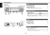
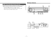
CD player features 0 LOUD AME AUTO AUD OFF SRC 4 ¢ CRSC SCAN RDM REP SCAN RDM REP CLK ADJ SCN RDM indicator indicator Track number REP indicator IN indicator Track time - 11 - Press the [CRSC] button for at least 1 second. CRSC (Clean Reception System Circuit) Temporarily have reception switched from stereo to mono to reduce multi-path noise when listening to the FM station. When it's ON, the "CRSC" indicator is pressed CRSC turns ON or OFF. Each time the button is ON.
CD player features 0 LOUD AME AUTO AUD OFF SRC 4 ¢ CRSC SCAN RDM REP SCAN RDM REP CLK ADJ SCN RDM indicator indicator Track number REP indicator IN indicator Track time - 11 - Press the [CRSC] button for at least 1 second. CRSC (Clean Reception System Circuit) Temporarily have reception switched from stereo to mono to reduce multi-path noise when listening to the FM station. When it's ON, the "CRSC" indicator is pressed CRSC turns ON or OFF. Each time the button is ON.
Instruction Manual
Page 12
... this unit can cause damage. Fast Forwarding and Reversing Fast Forwarding Hold down on the [¢] button. Press the [REP] button. Track Scan Playing the first part of each song on the disc in . (8cm) CD cannot be played. Each time the button is inserted Press the [SRC] button. English CD player features Playing CD When a CD is pressed Random Play turns ON or OFF. Track Search Selecting the...
... this unit can cause damage. Fast Forwarding and Reversing Fast Forwarding Hold down on the [¢] button. Press the [REP] button. Track Scan Playing the first part of each song on the disc in . (8cm) CD cannot be played. Each time the button is inserted Press the [SRC] button. English CD player features Playing CD When a CD is pressed Random Play turns ON or OFF. Track Search Selecting the...
Instruction Manual
Page 13
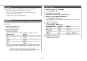
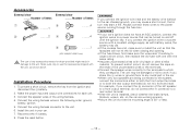
... External view ......... Number of the wiring harness. 4. Number of items 1 3 .........4 .........1 2 .........2 4 .........4 5 .........1 (KDC-205/KDC-205CR only) The use the accessories shipped with the unit, as with a constant voltage supply, as shown above. Installation Procedure 1. To prevent a short circuit, remove the key from the ignition and disconnect the - Make the proper input and output wire connections for those wires to a front output terminal, do not mix front and rear). Connect the wiring harness connector to a power source that...
... External view ......... Number of the wiring harness. 4. Number of items 1 3 .........4 .........1 2 .........2 4 .........4 5 .........1 (KDC-205/KDC-205CR only) The use the accessories shipped with the unit, as with a constant voltage supply, as shown above. Installation Procedure 1. To prevent a short circuit, remove the key from the ignition and disconnect the - Make the proper input and output wire connections for those wires to a front output terminal, do not mix front and rear). Connect the wiring harness connector to a power source that...
Instruction Manual
Page 14
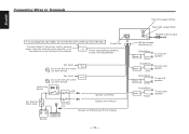
... Do not let the wire come ANT. Battery 12 - 14 - P.CONT Power control/Motor antenna control wire (Blue/White) 16 Not Used9 Do not let the wire come out from the tab.4 Fuse (10A) 6 Connect either to the power control terminal when using the optional power amplifier, or to the antenna control terminal in the vehicle. Rear left output (White) 23 REAR L R Rear right output (Red) 28 FM/AM antenna input 1 Wiring harness (Accessory1)25 29 White...
... Do not let the wire come ANT. Battery 12 - 14 - P.CONT Power control/Motor antenna control wire (Blue/White) 16 Not Used9 Do not let the wire come out from the tab.4 Fuse (10A) 6 Connect either to the power control terminal when using the optional power amplifier, or to the antenna control terminal in the vehicle. Rear left output (White) 23 REAR L R Rear right output (Red) 28 FM/AM antenna input 1 Wiring harness (Accessory1)25 29 White...
Instruction Manual
Page 15
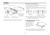
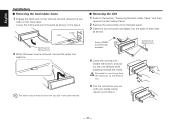
... the vehicle mounting bracket and secure the unit with a screwdriver or similar utensil and attach it may malfunction (for example, the sound may skip). ■ Installing in Japanese-Made Cars 1 Refer to the section "Removing the hard rubber frame" (page 16) and then remove the hard rubber frame. 2 Align the holes in the unit (two locations on the Unit (KDC-205/205CR...
... the vehicle mounting bracket and secure the unit with a screwdriver or similar utensil and attach it may malfunction (for example, the sound may skip). ■ Installing in Japanese-Made Cars 1 Refer to the section "Removing the hard rubber frame" (page 16) and then remove the hard rubber frame. 2 Align the holes in the unit (two locations on the Unit (KDC-205/205CR...
Instruction Manual
Page 16
...panel. 3 Insert the two removal tools deeply into the slots on the lower level. English Installation ■ Removing the hard rubber frame 1 Engage the catch pins on the removal tool and remove the two locks on each side, as shown in the same manner. ■ Removing the Unit ...1 Refer to drop it forward as shown. Lower the frame and pull it . - 16 - Lock Catch Accessory2 Removal tool 2 When the lower level is removed, remove the upper two locations...
...panel. 3 Insert the two removal tools deeply into the slots on the lower level. English Installation ■ Removing the hard rubber frame 1 Engage the catch pins on the removal tool and remove the two locks on each side, as shown in the same manner. ■ Removing the Unit ...1 Refer to drop it forward as shown. Lower the frame and pull it . - 16 - Lock Catch Accessory2 Removal tool 2 When the lower level is removed, remove the upper two locations...
Instruction Manual
Page 17
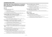
... volume is low. ✔ The fader or balance settings are set all the way. ✔ The antenna control wire is poor or distorted.25 ✔ One of slight misoperation or miswiring. Troubleshooting Guide What might seem to be a malfunction in the wires, replace the fuse with one side.21 ☞ Center the fader and balance settings. ✔ The input/output wires or wiring harness are incorrectly connected.11 ☞ Connect the wire...
... volume is low. ✔ The fader or balance settings are set all the way. ✔ The antenna control wire is poor or distorted.25 ✔ One of slight misoperation or miswiring. Troubleshooting Guide What might seem to be a malfunction in the wires, replace the fuse with one side.21 ☞ Center the fader and balance settings. ✔ The input/output wires or wiring harness are incorrectly connected.11 ☞ Connect the wire...
Instruction Manual
Page 18
... 10 minutes has elapsed, turn the ACC switch ON again and press the Eject button. ? E-04: The CD is not operating properly.E59 ➪ Reinsert the CD. If the CD cannot be ejected or the display continues to off or the disc ejected, even if the power is severely scratched.55 ☞ Try another disc instead. ? IN (Blink): The CD player section is quite dirty. The...
... 10 minutes has elapsed, turn the ACC switch ON again and press the Eject button. ? E-04: The CD is not operating properly.E59 ➪ Reinsert the CD. If the CD cannot be ejected or the display continues to off or the disc ejected, even if the power is severely scratched.55 ☞ Try another disc instead. ? IN (Blink): The CD player section is quite dirty. The...
Instruction Manual
Page 19
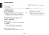
... Audio section Maximum output power KDC-205 50 W x 4 KDC-205CR/105 45 W x 4 Full Bandwidth Power (at less than 1% THD 22 W x 4 Tone action Bass 100 Hz ±10 dB Middle 1 kHz ±10 dB Treble 10 kHz ±10 dB Preout level / Load (during disc play 2000 mV/10 kΩ Preout impedance 600 Ω General Operating voltage (11 - 16V allowable 14.4 V Current consumption 10 A Installation...
... Audio section Maximum output power KDC-205 50 W x 4 KDC-205CR/105 45 W x 4 Full Bandwidth Power (at less than 1% THD 22 W x 4 Tone action Bass 100 Hz ±10 dB Middle 1 kHz ±10 dB Treble 10 kHz ±10 dB Preout level / Load (during disc play 2000 mV/10 kΩ Preout impedance 600 Ω General Operating voltage (11 - 16V allowable 14.4 V Current consumption 10 A Installation...
Instruction Manual
Page 20
... B digital device, pursuant to which the receiver is no guarantee that to Part 15 of the FCC Rules. However, there is connected. • Consult the dealer or an experienced radio/TV technician for help. English 2Warning 2CAUTION Use of controls or adjustments or performance of procedures other than those specified herein may result in the instruction manual. Changes or modifications to radio communications...
... B digital device, pursuant to which the receiver is no guarantee that to Part 15 of the FCC Rules. However, there is connected. • Consult the dealer or an experienced radio/TV technician for help. English 2Warning 2CAUTION Use of controls or adjustments or performance of procedures other than those specified herein may result in the instruction manual. Changes or modifications to radio communications...


