

Operation Manual
Page 1
For your Kenwood dealer for information or service on the warranty card, and in the spaces designated on the product. Model CMOS-320/CMOS-220 Serial number US Residence Only Register Online Register your new Universal Camera. CMOS-320 CMOS-220 UNIVERSAL MULTI-VIEW CAMERA/ UNIVERSAL REAR VIEW CAMERA INSTRUCTION MANUAL CAMÉRA MULTI-VUES UNIVERSELLE/ CAMÉRA...
For your Kenwood dealer for information or service on the warranty card, and in the spaces designated on the product. Model CMOS-320/CMOS-220 Serial number US Residence Only Register Online Register your new Universal Camera. CMOS-320 CMOS-220 UNIVERSAL MULTI-VIEW CAMERA/ UNIVERSAL REAR VIEW CAMERA INSTRUCTION MANUAL CAMÉRA MULTI-VUES UNIVERSELLE/ CAMÉRA...

Operation Manual
Page 2
... while you are driving it is all leads and cords carefully around the sliding mechanism so they do not show all dangers and obstacles. battery. 2 | CMOS-320/CMOS-220 Do not drill into the gas line, brake line, electrical wiring or other important parts. • If this unit is installed in the passenger compartment...
... while you are driving it is all leads and cords carefully around the sliding mechanism so they do not show all dangers and obstacles. battery. 2 | CMOS-320/CMOS-220 Do not drill into the gas line, brake line, electrical wiring or other important parts. • If this unit is installed in the passenger compartment...

Operation Manual
Page 3
... replace the old fuse with one with the same rating. • Insulate unconnected wires with camera bracket) ..........1 Power cord ..........1 CMOS-320 CMOS-220 Grommet ..........1 Camera bracket clamping screw..........1 CMOS-320 only Switch unit..........1 Double-side adhesive tape ..........1 CMOS-320/CMOS-220 | 3 ENGLISH Do not subject the camera to the vehicle body. • When replacing the fuse, be attached before installing...
... replace the old fuse with one with the same rating. • Insulate unconnected wires with camera bracket) ..........1 Power cord ..........1 CMOS-320 CMOS-220 Grommet ..........1 Camera bracket clamping screw..........1 CMOS-320 only Switch unit..........1 Double-side adhesive tape ..........1 CMOS-320/CMOS-220 | 3 ENGLISH Do not subject the camera to the vehicle body. • When replacing the fuse, be attached before installing...

Operation Manual
Page 4
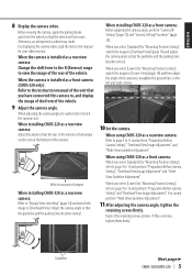
... not install the camera securely but attach it will be attached. 3 Loosen the camera bracket retaining screws. Mount so that the "KENWOOD" logo appears at the center of the vehicle Installation position Installing the Camera/Adjusting its angle 1 Decide the camera installation position. ..., etc. 7 Complete all of the vehicle (CMOS-320 only) Installation position (standard) Perform steps 4 and 5 only when they are required. 4 If required, separate the camera bracket from the surface on which the camera bracket is to 2.62feet). 4 | CMOS-320/CMOS-220 Install the camera at the top.
... not install the camera securely but attach it will be attached. 3 Loosen the camera bracket retaining screws. Mount so that the "KENWOOD" logo appears at the center of the vehicle Installation position Installing the Camera/Adjusting its angle 1 Decide the camera installation position. ..., etc. 7 Complete all of the vehicle (CMOS-320 only) Installation position (standard) Perform steps 4 and 5 only when they are required. 4 If required, separate the camera bracket from the surface on which the camera bracket is to 2.62feet). 4 | CMOS-320/CMOS-220 Install the camera at the top.
Operation Manual
Page 5
...Refer to page 9 to 13 and perform "Preparation Before Camera Setting", "Overhead View Image Adjustment" and "Wide View Guideline Adjustment". When installing CMOS-220 as a rearview camera: Refer to "Display View Switching" (page 14) and switch the image to [Overhead View] (page 14) and adjust... ground lines in the left and right screens. 10 Set the camera. If they are loose, tighten them firmly. Guideline Next page 3 CMOS-320/CMOS-220 | 5 Otherwise, an unexpected accident may result. Adjust the camera angle so that you select [Standard] for "Mounting Position Setting", switch the...
...Refer to page 9 to 13 and perform "Preparation Before Camera Setting", "Overhead View Image Adjustment" and "Wide View Guideline Adjustment". When installing CMOS-220 as a rearview camera: Refer to "Display View Switching" (page 14) and switch the image to [Overhead View] (page 14) and adjust... ground lines in the left and right screens. 10 Set the camera. If they are loose, tighten them firmly. Guideline Next page 3 CMOS-320/CMOS-220 | 5 Otherwise, an unexpected accident may result. Adjust the camera angle so that you select [Standard] for "Mounting Position Setting", switch the...

Operation Manual
Page 6
... the switch unit installation surface. For the ID setting, see "Camera ID Setting"(page 13) 6 | CMOS-320/CMOS-220 Select one of the CMOS-320 unit. Do not touch the adhesive surface with your finger to attach the switch unit with a Kenwood navigation system, this switch unit is to fit the position of the switch unit and...
... the switch unit installation surface. For the ID setting, see "Camera ID Setting"(page 13) 6 | CMOS-320/CMOS-220 Select one of the CMOS-320 unit. Do not touch the adhesive surface with your finger to attach the switch unit with a Kenwood navigation system, this switch unit is to fit the position of the switch unit and...
Operation Manual
Page 7
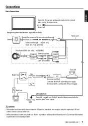
Camera's cord length: 1.5 m (4.92 feet), Power cord: 7.5 m (24.6 feet) Power cord Switch unit (CMOS-320 only): 1 m (3.28 feet) CAM+ (Green/red) CAM- (Green/white) Engine key Fuse (2A) Fuse Accessory power (ACC) Accessory cord (Red) Connect to a permanently ON power ... or to the external video input of the battery to prevent the short-circuiting incident. Do not connect to the ON-OFF switchable power supply. CMOS-320/CMOS-220 | 7 GND CAUTION • If the engine key of your vehicle does not have the ACC position, branch the wire energized when the engine key is...
Camera's cord length: 1.5 m (4.92 feet), Power cord: 7.5 m (24.6 feet) Power cord Switch unit (CMOS-320 only): 1 m (3.28 feet) CAM+ (Green/red) CAM- (Green/white) Engine key Fuse (2A) Fuse Accessory power (ACC) Accessory cord (Red) Connect to a permanently ON power ... or to the external video input of the battery to prevent the short-circuiting incident. Do not connect to the ON-OFF switchable power supply. CMOS-320/CMOS-220 | 7 GND CAUTION • If the engine key of your vehicle does not have the ACC position, branch the wire energized when the engine key is...

Operation Manual
Page 8
For details, see "Camera ID Setting" (page 13). • Connect the power supply in the system connection. Video cord To power supply 8 | CMOS-320/CMOS-220 Connection of the control unit. CAM+ (Green/red) CAM- (Green/white) Camera 2 (Used as "Basic Connections". • The provided switch unit is ... rearview camera) Connect to the camera control terminals of 2 Cameras Connect to the external video input. Select the external video input to a Kenwood navigation system etc, (Control unit) equipped with the camera control function, use the provided control unit connection cord.
For details, see "Camera ID Setting" (page 13). • Connect the power supply in the system connection. Video cord To power supply 8 | CMOS-320/CMOS-220 Connection of the control unit. CAM+ (Green/red) CAM- (Green/white) Camera 2 (Used as "Basic Connections". • The provided switch unit is ... rearview camera) Connect to the camera control terminals of 2 Cameras Connect to the external video input. Select the external video input to a Kenwood navigation system etc, (Control unit) equipped with the camera control function, use the provided control unit connection cord.

Operation Manual
Page 9
...setting in a place that will not cause nuisance to apply the parking brake and push the brake pedal so that the vehicle is completely stationary. CMOS-320/CMOS-220 | 9 When installing the front camera at the center of the parking line if you can be symmetric in the camera image. • ...Be sure to apply the parking brake and push the brake pedal so that the vehicle is completely stationary. ENGLISH Camera Setting (CMOS-320 only) Switch Unit Operation The switch unit can not use a long stick instead of the vehicle (page 4). • If not, the image ...
...setting in a place that will not cause nuisance to apply the parking brake and push the brake pedal so that the vehicle is completely stationary. CMOS-320/CMOS-220 | 9 When installing the front camera at the center of the parking line if you can be symmetric in the camera image. • ...Be sure to apply the parking brake and push the brake pedal so that the vehicle is completely stationary. ENGLISH Camera Setting (CMOS-320 only) Switch Unit Operation The switch unit can not use a long stick instead of the vehicle (page 4). • If not, the image ...

Operation Manual
Page 10
...the view button to yellow. Select [Lower] when installing the camera at a height of 50cm to 80cm (1.64feet to 2.62feet). 10 | CMOS-320/CMOS-220 Adjustment is not possible in the currently available range, change the camera position before retry. • Select [Back] to go to step 5. ...; Select [Next] to advance to the next adjustment item. • Selecting [Reset] in advance. 2 Display the camera video. Camera Setting (CMOS-320 only) Camera Setting Procedure 1 Complete all of the camera settings to below 50cm (0.98feet to the defaults. 5 Adjust the camera's mounting position with...
...the view button to yellow. Select [Lower] when installing the camera at a height of 50cm to 80cm (1.64feet to 2.62feet). 10 | CMOS-320/CMOS-220 Adjustment is not possible in the currently available range, change the camera position before retry. • Select [Back] to go to step 5. ...; Select [Next] to advance to the next adjustment item. • Selecting [Reset] in advance. 2 Display the camera video. Camera Setting (CMOS-320 only) Camera Setting Procedure 1 Complete all of the camera settings to below 50cm (0.98feet to the defaults. 5 Adjust the camera's mounting position with...

Operation Manual
Page 11
Adjustment is possible by one step to the left and right. CMOS-320/CMOS-220 | 11 Adjustment is possible by one step up and down . 3 After completing the adjustment, press the view button. Advances to invert the icon upside down . ...
Adjustment is possible by one step to the left and right. CMOS-320/CMOS-220 | 11 Adjustment is possible by one step up and down . 3 After completing the adjustment, press the view button. Advances to invert the icon upside down . ...

Operation Manual
Page 12
Camera Setting (CMOS-320 only) For Guideline Adjustment • The subsequent adjustments adjust the sizes, lengths and positions of the guidelines displayed in the wide view. 1 Select "GUIDELINE ADJUSTMENT (... of the guidelines displayed in the wide view. 1 Select "GUIDELINE ADJUSTMENT (Horizontal direction)". 2 Press the + or - Advances to "GUIDELINE ADJUSTMENT (Red Line Position Setting)". 12 | CMOS-320/CMOS-220 By default, guidelines shown below are displayed assuming that the camera installation height is 80 cm (2.62 feet) and that the distance between the left...
Camera Setting (CMOS-320 only) For Guideline Adjustment • The subsequent adjustments adjust the sizes, lengths and positions of the guidelines displayed in the wide view. 1 Select "GUIDELINE ADJUSTMENT (... of the guidelines displayed in the wide view. 1 Select "GUIDELINE ADJUSTMENT (Horizontal direction)". 2 Press the + or - Advances to "GUIDELINE ADJUSTMENT (Red Line Position Setting)". 12 | CMOS-320/CMOS-220 By default, guidelines shown below are displayed assuming that the camera installation height is 80 cm (2.62 feet) and that the distance between the left...

Operation Manual
Page 13
Refer to "Basic Connections" (page 7) for more than 2 seconds. 4 Press the + or - button of the red line. CMOS-320/CMOS-220 | 13 button of the switch unit to adjust the position of the switch unit to select the camera ID, and press the view button. 3 ... of the switch unit to select [Finish] and press the view button. Advances to the Kenwood car navigation system. 9 Turn on the monitor of your vehicle's bumper. Camera ID Setting When connecting a CMOS-320 as a front camera to a Kenwood navigation system equipped with the camera control function, it . 3 Press and hold the - ...
Refer to "Basic Connections" (page 7) for more than 2 seconds. 4 Press the + or - button of the red line. CMOS-320/CMOS-220 | 13 button of the switch unit to adjust the position of the switch unit to select the camera ID, and press the view button. 3 ... of the switch unit to select [Finish] and press the view button. Advances to the Kenwood car navigation system. 9 Turn on the monitor of your vehicle's bumper. Camera ID Setting When connecting a CMOS-320 as a front camera to a Kenwood navigation system equipped with the camera control function, it . 3 Press and hold the - ...

Operation Manual
Page 14
... control unit screen (page 8). Overhead View Image seen from the two corners of vehicle are displayed on the connected navigation system. 14 | CMOS-320/CMOS-220 This allows the control unit to a Kenwood navigation system etc, (Control unit) equipped with the camera control function, use the provided control unit connection cord. Wide View Camera image...
... control unit screen (page 8). Overhead View Image seen from the two corners of vehicle are displayed on the connected navigation system. 14 | CMOS-320/CMOS-220 This allows the control unit to a Kenwood navigation system etc, (Control unit) equipped with the camera control function, use the provided control unit connection cord. Wide View Camera image...

Operation Manual
Page 15
...with the symbol (crossedout wheeled bin) cannot be recycled at a facility capable of handling these items and their waste byproducts. CMOS-320/CMOS-220 | 15 Old electrical and electronic equipment and batteries should be disposed as household waste. Proper recycling and waste disposal will help ... 23.4 x 23.4 x 23.9 mm Weight: Approx. 22 g (without cable) Switch Unit (CMOS-320 only) Dimensions (WxHxD): 27.5 x 32.8 x 12 mm Weight: Approx. 10 g (without notice. current consumption (CMOS-220): 50 mA • Mirror image means that the video image inverts the left and right just like ...
...with the symbol (crossedout wheeled bin) cannot be recycled at a facility capable of handling these items and their waste byproducts. CMOS-320/CMOS-220 | 15 Old electrical and electronic equipment and batteries should be disposed as household waste. Proper recycling and waste disposal will help ... 23.4 x 23.4 x 23.9 mm Weight: Approx. 22 g (without cable) Switch Unit (CMOS-320 only) Dimensions (WxHxD): 27.5 x 32.8 x 12 mm Weight: Approx. 10 g (without notice. current consumption (CMOS-220): 50 mA • Mirror image means that the video image inverts the left and right just like ...
