
Operation Manual
Page 7
REAR L+ REAR L- PURPLE + REAR R PURPLE/BLACK - VM9512 WIRING DIAGRAM * See the MediaLink and Satellite Connections diagram for more information about connecting a satellite receiver and an iPod (through the MediaLink). GREEN + REAR L GREEN/BLACK - 3 PINK PRK SW GREEN/WHITE REVERSE + RED ACC YELLOW BATT BLACK GND...Car Phone P.CONT Car Mute (leave open if not connected) BROWN MUTE HEADPHONE MULTIZONE MZ-TFT CAMERA BLACK MZ-TFT Touch Screen (Sold Separately) WHITE RED WIRELESS HEADPHONE (OPTIONAL) Rear View YELLOW YELLOW Video Camera FRONT L+ FRONT L- FRONT R+ FRONT R-
REAR L+ REAR L- PURPLE + REAR R PURPLE/BLACK - VM9512 WIRING DIAGRAM * See the MediaLink and Satellite Connections diagram for more information about connecting a satellite receiver and an iPod (through the MediaLink). GREEN + REAR L GREEN/BLACK - 3 PINK PRK SW GREEN/WHITE REVERSE + RED ACC YELLOW BATT BLACK GND...Car Phone P.CONT Car Mute (leave open if not connected) BROWN MUTE HEADPHONE MULTIZONE MZ-TFT CAMERA BLACK MZ-TFT Touch Screen (Sold Separately) WHITE RED WIRELESS HEADPHONE (OPTIONAL) Rear View YELLOW YELLOW Video Camera FRONT L+ FRONT L- FRONT R+ FRONT R-
Operation Manual
Page 9
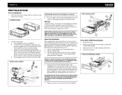
...mounted within 20° of the tabs outward as illustrated in the wiring diagram on ). Bend the strap to position it to vibration. 5. Slide radio chassis into place. PREPARE RADIO BAND AS Press Audio VM9512 DISP OPEN Enter 2. Install adapter if necessary (optional). Install half-...through the mounting sleeve. NOTE: For proper operation of the perforated support strap (supplied) to damage the car wiring. 3. c. d. FINAL ISO-DIN INSTALLATION 3 BAND AS Press Audio VM9512 DISP OPEN Enter 4 1 2 5 Reinstall dash panel. Be careful not to the screw stud on new radio...
...mounted within 20° of the tabs outward as illustrated in the wiring diagram on ). Bend the strap to position it to vibration. 5. Slide radio chassis into place. PREPARE RADIO BAND AS Press Audio VM9512 DISP OPEN Enter 2. Install adapter if necessary (optional). Install half-...through the mounting sleeve. NOTE: For proper operation of the perforated support strap (supplied) to damage the car wiring. 3. c. d. FINAL ISO-DIN INSTALLATION 3 BAND AS Press Audio VM9512 DISP OPEN Enter 4 1 2 5 Reinstall dash panel. Be careful not to the screw stud on new radio...

Operation Manual
Page 39
VM9512 TROUBLESHOOTING Table 7: Troubleshooting Problem Cause Corrective Action GENERAL Unit will not power on Radio Fuse blown Car battery fuse blown Illegal operation Remote control does ... Review wiring diagram and check "MUTE" connection Replace speakers Adjust the channel balance to the center position Insulate all speaker wiring connections Use original copy Connect proper speakers Check speaker contact Check that the "MUTE" connection is not grounded and that it's properly insulated Check wiring and correct Turn TFT Auto Open on screen DVD...
VM9512 TROUBLESHOOTING Table 7: Troubleshooting Problem Cause Corrective Action GENERAL Unit will not power on Radio Fuse blown Car battery fuse blown Illegal operation Remote control does ... Review wiring diagram and check "MUTE" connection Replace speakers Adjust the channel balance to the center position Insulate all speaker wiring connections Use original copy Connect proper speakers Check speaker contact Check that the "MUTE" connection is not grounded and that it's properly insulated Check wiring and correct Turn TFT Auto Open on screen DVD...


