Installation Guide
Page 1
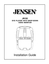
® JN102 DVD PLAYER WITH DROP-DOWN VIDEO MONITOR SOURCE Installation Guide
® JN102 DVD PLAYER WITH DROP-DOWN VIDEO MONITOR SOURCE Installation Guide
Installation Guide
Page 2
... must be installed to the rear of the chassis. This relay box is used for television reception, video or DVD play that these features will not be visible, directly or indirectly, to the operator of the wireless signal may be installed in a motor vehicle and visible to the driver if the LCD panel or video monitor is installed between the vehicle antenna and the car radio to provide...
... must be installed to the rear of the chassis. This relay box is used for television reception, video or DVD play that these features will not be visible, directly or indirectly, to the operator of the wireless signal may be installed in a motor vehicle and visible to the driver if the LCD panel or video monitor is installed between the vehicle antenna and the car radio to provide...
Installation Guide
Page 4
... in such a manner that it will need to be cut into the vehicle (headliner, other type of mounting. Be sure that all wiring is protected from their respective locations. 7) Connect all components together (electrically) and verify proper operation of all system functions. Note: This is not intended for horizontal, drop down installation. The JN102 video systems are only intended for wireless FM Modulator...
... in such a manner that it will need to be cut into the vehicle (headliner, other type of mounting. Be sure that all wiring is protected from their respective locations. 7) Connect all components together (electrically) and verify proper operation of all system functions. Note: This is not intended for horizontal, drop down installation. The JN102 video systems are only intended for wireless FM Modulator...
Installation Guide
Page 5
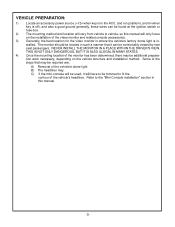
... DRIVER'S VIEW. and run positions, and 0v when key is off), and also a good ground generally, these wires can be found at the ignition switch or fuse-box. 2) The mounting method and location will vary from vehicle to fit the contour of the vehicle's dome light B) The headliner may be additional preparation work necessary, depending on the installation of the video monitor...
... DRIVER'S VIEW. and run positions, and 0v when key is off), and also a good ground generally, these wires can be found at the ignition switch or fuse-box. 2) The mounting method and location will vary from vehicle to fit the contour of the vehicle's dome light B) The headliner may be additional preparation work necessary, depending on the installation of the video monitor...
Installation Guide
Page 6
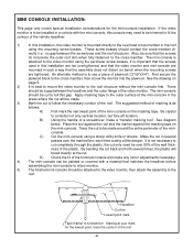
... cut only need to the video monitor using the perimeter screw bosses. B) Using the handle of the plastic. See diagram below. Make the cut back and forth several passes over 50% of the wall thickness of a screwdriver, make any minor adjustments necessary. 4)...used in this installation are not overtightened, and that the video monitor and mini-console are mounted in several times, the plastic will be trimmed to fit the contour of marking is not necessary to cut completely through the plastic, the cut to full this installation, the video monitor is mounted directly to the overhead...
... cut only need to the video monitor using the perimeter screw bosses. B) Using the handle of the plastic. See diagram below. Make the cut back and forth several passes over 50% of the wall thickness of a screwdriver, make any minor adjustments necessary. 4)...used in this installation are not overtightened, and that the video monitor and mini-console are mounted in several times, the plastic will be trimmed to fit the contour of marking is not necessary to cut completely through the plastic, the cut to full this installation, the video monitor is mounted directly to the overhead...
Installation Guide
Page 7
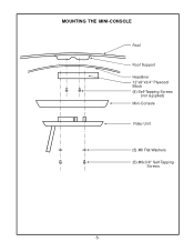
MOUNTING THE MINI-CONSOLE Roof Roof Support Headliner 12"x9"x3/4" Plywood Block (4) Self-Tapping Screws (not supplied) Mini-Console Video Unit (5) #8 Flat Washers (5) #8x3/4" Self-Tapping Screws -5-
MOUNTING THE MINI-CONSOLE Roof Roof Support Headliner 12"x9"x3/4" Plywood Block (4) Self-Tapping Screws (not supplied) Mini-Console Video Unit (5) #8 Flat Washers (5) #8x3/4" Self-Tapping Screws -5-
Installation Guide
Page 8
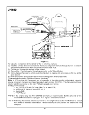
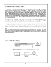
... Antenna In Dome Light Power Source Accessory Harness - This harness would plug into the Mini-Din connector on the Video Monitor. 5) Connect power harness to vehicle's electrical system by tapping into the Mini-Din Connector on the main PCB. 3) Pull the wire tie loop tight and cut off the excess. 4) Connect the 12 pin harness to the video monitor system using a second source component harness (purchased separately, part number: 8010730). A/V Source Definitions: 1= AV1, VCP or VCP with Non-Stereo Installations...
... Antenna In Dome Light Power Source Accessory Harness - This harness would plug into the Mini-Din connector on the Video Monitor. 5) Connect power harness to vehicle's electrical system by tapping into the Mini-Din Connector on the main PCB. 3) Pull the wire tie loop tight and cut off the excess. 4) Connect the 12 pin harness to the video monitor system using a second source component harness (purchased separately, part number: 8010730). A/V Source Definitions: 1= AV1, VCP or VCP with Non-Stereo Installations...
Installation Guide
Page 9
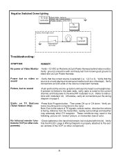
... purple / brown (Lamp auto) wire be connected to the door pin switch wire, as the additional current draw of the Monitor's lights may not be supported by the output of these wires will rest at ground. On a positive switched system, with all the doors closed and the lights out, both wires at the dome light will switch to a good ground. When the light is activated, one of the vehicles...
... purple / brown (Lamp auto) wire be connected to the door pin switch wire, as the additional current draw of the Monitor's lights may not be supported by the output of these wires will rest at ground. On a positive switched system, with all the doors closed and the lights out, both wires at the dome light will switch to a good ground. When the light is activated, one of the vehicles...
Installation Guide
Page 10
... ajar switch or Body To constant Troubleshooting: SYMPTOM: REMEDY: No power at Video Monitor -Verify +12 VDC on page 6. No Infrared remote func- -Check batteries in the following: picture roll, "snowy" picture, or momentary loss of color. Static on connector Black / red - Then press CH up button until sound is facing, distance from known good ground to instructions with this kit). Verify antenna mounting and connections...
... ajar switch or Body To constant Troubleshooting: SYMPTOM: REMEDY: No power at Video Monitor -Verify +12 VDC on page 6. No Infrared remote func- -Check batteries in the following: picture roll, "snowy" picture, or momentary loss of color. Static on connector Black / red - Then press CH up button until sound is facing, distance from known good ground to instructions with this kit). Verify antenna mounting and connections...
Installation Guide
Page 11
For Customer Service WWVWisi.taOuudr Wioevbosixte.cAtom Product Information, Photos, FAQ's Owner's Manuals 128-7390BA © Copyright 2006 Audiovox Electronics Corp. 150 Marcus Blvd. Hauppauge, NY 11788
For Customer Service WWVWisi.taOuudr Wioevbosixte.cAtom Product Information, Photos, FAQ's Owner's Manuals 128-7390BA © Copyright 2006 Audiovox Electronics Corp. 150 Marcus Blvd. Hauppauge, NY 11788


