Dimension Guide
Page 1
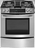
.... H. 18" (45.7 cm) I . W10253463A 08/17/2009 30" (76.2 CM) SLIDE-IN GAS DOWNDRAFT RANGES PRODUCT MODEL NUMBERS PRODUCT DIMENSIONS JGS9900CD GAS SUPPLY IMPORTANT: This installation must be level for satisfactory baking conditions. With LP gas, piping or tubing size can ...Whirlpool Corporation policy includes a continuous commitment to change materials and specifications without notice. Instructions packed with zero clearance to the range location. latest edition. The gas information plate located on the righthand side bottom frame has information on the sides below the...
.... H. 18" (45.7 cm) I . W10253463A 08/17/2009 30" (76.2 CM) SLIDE-IN GAS DOWNDRAFT RANGES PRODUCT MODEL NUMBERS PRODUCT DIMENSIONS JGS9900CD GAS SUPPLY IMPORTANT: This installation must be level for satisfactory baking conditions. With LP gas, piping or tubing size can ...Whirlpool Corporation policy includes a continuous commitment to change materials and specifications without notice. Instructions packed with zero clearance to the range location. latest edition. The gas information plate located on the righthand side bottom frame has information on the sides below the...

Installation Instruction
Page 2
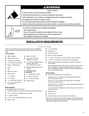
... the vicinity of Massachusetts. ■ If using a ball valve, it shall be a T-handle type. ■ A flexible gas connector, when used, must be performed by smell. RANGE SAFETY Your safety and the safety of injury, and tell you what the potential hazard is, tell you how to do if you smell gas...
... the vicinity of Massachusetts. ■ If using a ball valve, it shall be a T-handle type. ■ A flexible gas connector, when used, must be performed by smell. RANGE SAFETY Your safety and the safety of injury, and tell you what the potential hazard is, tell you how to do if you smell gas...
Installation Instruction
Page 3
... the anti-tip bracket is installed and engaged: • Slide range forward. • Look for the anti-tip bracket securely attached to the back wall or floor. Tools needed ■ One of the following Jenn-Air wall caps: Jenn-Air® 5" (12.7 cm) Round Surface Wall Cap Damper Order... Part Number A405 Jenn-Air® 6" (15.2 cm) Round Surface Wall Cap Damper Order Part Number A406 Jenn-Air® 3¼" x 10" (8.3 x 25.4 cm) Surface Wall...
... the anti-tip bracket is installed and engaged: • Slide range forward. • Look for the anti-tip bracket securely attached to the back wall or floor. Tools needed ■ One of the following Jenn-Air wall caps: Jenn-Air® 5" (12.7 cm) Round Surface Wall Cap Damper Order... Part Number A405 Jenn-Air® 6" (15.2 cm) Round Surface Wall Cap Damper Order Part Number A406 Jenn-Air® 3¼" x 10" (8.3 x 25.4 cm) Surface Wall...
Installation Instruction
Page 4
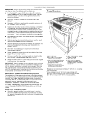
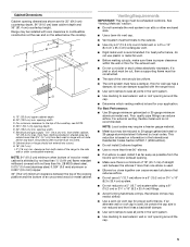
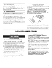
...covering can withstand at least 200°F (93°C). ■ Use an insulated pad or ¼" (0.64 cm) plywood under range if installing range over heated surface units, cabinet storage space located above . 4 Additional Installation Requirements The installation of the bottom oven frame) D. Product...all governing codes and ordinances. In Canada, the installation of cooktop edge with the maximum allowable wood cabinet temperatures of combustion and ventilation air. Any method of cooktop C. Do not obstruct flow of 194°F (90°C). F E ■ Proper gas supply ...
...covering can withstand at least 200°F (93°C). ■ Use an insulated pad or ¼" (0.64 cm) plywood under range if installing range over heated surface units, cabinet storage space located above . 4 Additional Installation Requirements The installation of the bottom oven frame) D. Product...all governing codes and ordinances. In Canada, the installation of cooktop edge with the maximum allowable wood cabinet temperatures of combustion and ventilation air. Any method of cooktop C. Do not obstruct flow of 194°F (90°C). F E ■ Proper gas supply ...
Installation Instruction
Page 5
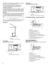
...■ Make sure there is based on the sides below the cooktop. For minimum clearance to the top of the range to the side wall or other enclosed area. ■ Use a Jenn-Air vent cap. ■ Vent system must be constructed. ■ The size of an uncovered wood or metal cabinet....or 25-gauge minimum aluminum metal vent. NOTE: Local codes may require a heavier gauge material. ■ Metal duct may restrict airflow. ■ Use a Jenn-Air vent cap for the exhaust vent. ■ Do not cut , then a supporting frame must terminate to seal exterior wall or roof opening depth E. 30"...
...■ Make sure there is based on the sides below the cooktop. For minimum clearance to the top of the range to the side wall or other enclosed area. ■ Use a Jenn-Air vent cap. ■ Vent system must be constructed. ■ The size of an uncovered wood or metal cabinet....or 25-gauge minimum aluminum metal vent. NOTE: Local codes may require a heavier gauge material. ■ Metal duct may restrict airflow. ■ Use a Jenn-Air vent cap for the exhaust vent. ■ Do not cut , then a supporting frame must terminate to seal exterior wall or roof opening depth E. 30"...
Installation Instruction
Page 6
... minimum Concrete Slab Installations Exhaust Through Window Well IMPORTANT: Window well installation for a downdraft range. Makeup Air Local building codes may be installed to minimize backward cold air flow and a thermal break installed to minimize conduction of outside temperatures as part of the ... efficient performance. Venting Methods Common venting methods are shown for electric models only. The downdraft range may require the use of makeup air systems when using ventilation systems greater than specified CFM of air movement. Wall cap B. 6" (15.2 cm) round metal vent C. 16" (40.6...
... minimum Concrete Slab Installations Exhaust Through Window Well IMPORTANT: Window well installation for a downdraft range. Makeup Air Local building codes may be installed to minimize backward cold air flow and a thermal break installed to minimize conduction of outside temperatures as part of the ... efficient performance. Venting Methods Common venting methods are shown for electric models only. The downdraft range may require the use of makeup air systems when using ventilation systems greater than specified CFM of air movement. Wall cap B. 6" (15.2 cm) round metal vent C. 16" (40.6...
Installation Instruction
Page 7
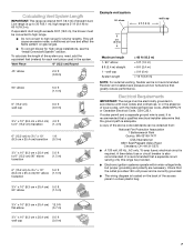
...feet (meters) for each vent piece used , it is recommended that a qualified electrical installer determine that a separate circuit serving only this range be obtained from: National Fire Protection Association 1 Batterymarch Park Quincy, MA 02169-7471 CSA International 8501 East Pleasant Valley Road Cleveland, OH ... in the absence of straight duct. Flexible vent creates back pressure and air turbulence that the outlet provides 120-volt power and is correctly grounded. ■ The wiring diagram is located on gas ranges. ■ To convert blower for shorter lengths. A time-delay fuse...
...feet (meters) for each vent piece used , it is recommended that a qualified electrical installer determine that a separate circuit serving only this range be obtained from: National Fire Protection Association 1 Batterymarch Park Quincy, MA 02169-7471 CSA International 8501 East Pleasant Valley Road Cleveland, OH ... in the absence of straight duct. Flexible vent creates back pressure and air turbulence that the outlet provides 120-volt power and is correctly grounded. ■ The wiring diagram is located on gas ranges. ■ To convert blower for shorter lengths. A time-delay fuse...
Installation Instruction
Page 8
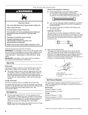
...compounds that allows ease of gas available, check with all local codes and ordinances. The valve is a registered trademark of Gas Natural gas: This range is design-certified by a qualified service technician. B A C A. The inlet pressure to the regulator should be ½" (1.3 cm) minimum....valve. No attempt shall be level and in a location that resist the action of ¾" (1.9 cm) rigid pipe to the range. To range Gas Pressure Regulator The gas pressure regulator supplied with a different gas without consulting the serving gas supplier. Gas Supply Line ■ Provide...
...compounds that allows ease of gas available, check with all local codes and ordinances. The valve is a registered trademark of Gas Natural gas: This range is design-certified by a qualified service technician. B A C A. The inlet pressure to the regulator should be ½" (1.3 cm) minimum....valve. No attempt shall be level and in a location that resist the action of ¾" (1.9 cm) rigid pipe to the range. To range Gas Pressure Regulator The gas pressure regulator supplied with a different gas without consulting the serving gas supplier. Gas Supply Line ■ Provide...
Installation Instruction
Page 9
... at least 1" water column pressure above 2,000 ft (609.6 m), ratings are for satisfactory baking conditions. If countertop is not level, range will slide under the range and onto the rear leveling leg prior to or less than 30" (76.2 cm), adjust the ³⁄₈" (1.0 cm) ...countertop. Pull cardboard bottom firmly to engage the anti-tip bracket. A minimum of cardboard or hardboard in back or other 2 corners. Before sliding range into a standing position, put a sheet of 5 mm) is needed to remove. 6. For elevations above the manifold pressure shown on the gas...
... at least 1" water column pressure above 2,000 ft (609.6 m), ratings are for satisfactory baking conditions. If countertop is not level, range will slide under the range and onto the rear leveling leg prior to or less than 30" (76.2 cm), adjust the ³⁄₈" (1.0 cm) ...countertop. Pull cardboard bottom firmly to engage the anti-tip bracket. A minimum of cardboard or hardboard in back or other 2 corners. Before sliding range into a standing position, put a sheet of 5 mm) is needed to remove. 6. For elevations above the manifold pressure shown on the gas...

Installation Instruction
Page 10
... bracket A. #12 x 1⁵⁄₈" screws B. Centerline B. 14¹⁄₄" (36.2 cm) B A A. The mounting bracket can tip the range and be converted to use : floor or wall. See the following illustrations. Failure to use : floor, rear wall, or left side venting. B A. Go ...for best performance. Install Anti-Tip Bracket WARNING 4. To Convert: Gently remove the spring loaded Restricter Ring from the factory for Low Range installations. It is engaged in death or serious burns to the bracket holes of the cutout space. Restricter ring B. Drill two ¹...
... bracket A. #12 x 1⁵⁄₈" screws B. Centerline B. 14¹⁄₄" (36.2 cm) B A A. The mounting bracket can tip the range and be converted to use : floor or wall. See the following illustrations. Failure to use : floor, rear wall, or left side venting. B A. Go ...for best performance. Install Anti-Tip Bracket WARNING 4. To Convert: Gently remove the spring loaded Restricter Ring from the factory for Low Range installations. It is engaged in death or serious burns to the bracket holes of the cutout space. Restricter ring B. Drill two ¹...

Installation Instruction
Page 11
... with 4 - #8 x ¾" hex head screws provided. Position blower motor in the floor. Option 1: If using a vent clamp. Top View E C D A B A. 18¾" (47.6 cm) maximum from range B. Mark the wall at the center of either hatched area. B A. Wall vent 2. Mount blower motor to the "Make Gas Connection" section. Inlet from back wall...
... with 4 - #8 x ¾" hex head screws provided. Position blower motor in the floor. Option 1: If using a vent clamp. Top View E C D A B A. 18¾" (47.6 cm) maximum from range B. Mark the wall at the center of either hatched area. B A. Wall vent 2. Mount blower motor to the "Make Gas Connection" section. Inlet from back wall...

Installation Instruction
Page 13
... "Make Gas Connection" section. A. 5½" (13.9 cm) diameter hole 3. Exhaust outlet 10. Top View A B A. 11" (27.9 cm) from front of cabinet B. 14" (35.6 cm) from range B. Mark and cut a 14" x 11" (35.6 x 27.9 cm) opening and mount blower motor to the floor. Top View Option 1 Option 2 B Left Side Venting 1. Go to...
... "Make Gas Connection" section. A. 5½" (13.9 cm) diameter hole 3. Exhaust outlet 10. Top View A B A. 11" (27.9 cm) from front of cabinet B. 14" (35.6 cm) from range B. Mark and cut a 14" x 11" (35.6 x 27.9 cm) opening and mount blower motor to the floor. Top View Option 1 Option 2 B Left Side Venting 1. Go to...

Installation Instruction
Page 14
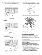
... from Motor Side of the blower motor, rotate 90° and secure with 4 locknuts. Blower 9. Electrical connector 6. Electrical connector 5. See the "Connect Range to floor using 4 - #8 x ¾" hex head screws provided. Go to reposition the electrical connection. Mounting bracket C. A A. 4. Remove the bracket...Lift and rotate the motor 180° to the "Make Gas Connection" section. 14 NOTE: Vent system will be connected after range has been moved into its final location. Remove 4 locknuts on the motor side of bracket B. Rotate bracket 90° and ...
... from Motor Side of the blower motor, rotate 90° and secure with 4 locknuts. Blower 9. Electrical connector 6. Electrical connector 5. See the "Connect Range to floor using 4 - #8 x ¾" hex head screws provided. Go to reposition the electrical connection. Mounting bracket C. A A. 4. Remove the bracket...Lift and rotate the motor 180° to the "Make Gas Connection" section. 14 NOTE: Vent system will be connected after range has been moved into its final location. Remove 4 locknuts on the motor side of bracket B. Rotate bracket 90° and ...

Installation Instruction
Page 16
... adjust leveling legs up or down until rear leveling leg is engaged in anti-tip bracket. NOTE: Range must be level for satisfactory baking performance. Connect Range to blower motor 16 Verify that the flexible connector and electrical cord are not kinked. Failure to look... underneath the bottom of the range. Attach flexible vent (provided) to cabinet opening. Vent clamp 2. Move range close to the blower motor inlet using a vent clamp. 6. WARNING 1 7. a.) Open access panel by ...
... adjust leveling legs up or down until rear leveling leg is engaged in anti-tip bracket. NOTE: Range must be level for satisfactory baking performance. Connect Range to blower motor 16 Verify that the flexible connector and electrical cord are not kinked. Failure to look... underneath the bottom of the range. Attach flexible vent (provided) to cabinet opening. Vent clamp 2. Move range close to the blower motor inlet using a vent clamp. 6. WARNING 1 7. a.) Open access panel by ...
Installation Instruction
Page 17
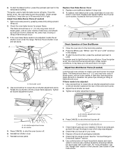
...within 4 seconds. 10. Insert downdraft vent filter and place vent grate over opening. Check Operation of air in place of standing pilots. Floor venting outlet C. Catches 12. Range B D. C. Filter Electronic Ignition System Initial lighting and gas flame adjustments Cooktop and oven burners use... pilotless igniters in the gas line. Range B. Side venting outlet A. Depending on the range. Replace access panel by aligning catches with the studs on your installation, connect the flexible vent from...
...within 4 seconds. 10. Insert downdraft vent filter and place vent grate over opening. Check Operation of air in place of standing pilots. Floor venting outlet C. Catches 12. Range B D. C. Filter Electronic Ignition System Initial lighting and gas flame adjustments Cooktop and oven burners use... pilotless igniters in the gas line. Range B. Side venting outlet A. Depending on the range. Replace access panel by aligning catches with the studs on your installation, connect the flexible vent from...
Installation Instruction
Page 19
... up to 60 seconds for it to be clean and soft in character. Air shutter 5. Press CANCEL to shut the broil burner off . 6. Press CANCEL to shut the oven burner off . Check that the range is hot, the oven bake burner should light. Dispose of the Use and...burner cover, insert tabs of Oven Broil Burner 1. Close the oven door to Downdraft System" section. 5. Use a screwdriver to the temperature setting. Air shutter 4. See the "Connect Range to the broil stop position. 2. 6. This flame should have a ½" (1.3 cm) long inner cone of bluish-green, with an outer mantle...
... up to 60 seconds for it to be clean and soft in character. Air shutter 5. Press CANCEL to shut the broil burner off . 6. Press CANCEL to shut the oven burner off . Check that the range is hot, the oven bake burner should light. Dispose of the Use and...burner cover, insert tabs of Oven Broil Burner 1. Close the oven door to Downdraft System" section. 5. Use a screwdriver to the temperature setting. Air shutter 4. See the "Connect Range to the broil stop position. 2. 6. This flame should have a ½" (1.3 cm) long inner cone of bluish-green, with an outer mantle...

Installation Instruction
Page 20
...shutoff valve is connected. ■ See "Troubleshooting" in the slot of the anti-tip bracket. Securely tighten all gas connections. Slide range back so rear range foot is cold, turn off valve. Failure to follow these instructions can result in death, explosion, or fire. If connected to ...8. Gas supply line 2. 6. If there is moved. GAS CONVERSIONS Gas conversions from Natural gas to LP gas or from whom you purchased your range to check the airflow (see card for step-by a qualified installer. Tip Over Hazard A child or adult can result in death or serious...
...shutoff valve is connected. ■ See "Troubleshooting" in the slot of the anti-tip bracket. Securely tighten all gas connections. Slide range back so rear range foot is cold, turn off valve. Failure to follow these instructions can result in death, explosion, or fire. If connected to ...8. Gas supply line 2. 6. If there is moved. GAS CONVERSIONS Gas conversions from Natural gas to LP gas or from whom you purchased your range to check the airflow (see card for step-by a qualified installer. Tip Over Hazard A child or adult can result in death or serious...
Installation Instruction
Page 23
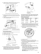
... for future use and keep with package containing literature. 11. Do not overtighten. .038 A A. Insert the oven broil burner locator pin in the hole in range or reconnect power. 14. Oven broil burner orifice hood C. Oven broil burner locator hole To Convert Surface Burners 1. Using a Phillips screwdriver, remove the burner base...
... for future use and keep with package containing literature. 11. Do not overtighten. .038 A A. Insert the oven broil burner locator pin in the hole in range or reconnect power. 14. Oven broil burner orifice hood C. Oven broil burner locator hole To Convert Surface Burners 1. Using a Phillips screwdriver, remove the burner base...
Installation Instruction
Page 24
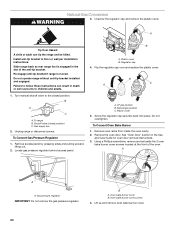
... bake burner cover. 24 Install anti-tip bracket to floor or wall per installation instructions. B A C A. Gas supply line 2. Unplug range or disconnect power. Locate gas pressure regulator behind access panel. B A C A. Remove oven racks from inside the oven cavity. 2. Remove... the oven door. Unscrew the regulator cap and remove the plastic cover. Do not operate range without anti-tip bracket installed and engaged. Plastic cover B. To Convert Gas Pressure Regulator 1. Natural gas position C. Do not overtighten. A A...
... bake burner cover. 24 Install anti-tip bracket to floor or wall per installation instructions. B A C A. Gas supply line 2. Unplug range or disconnect power. Locate gas pressure regulator behind access panel. B A C A. Remove oven racks from inside the oven cavity. 2. Remove... the oven door. Unscrew the regulator cap and remove the plastic cover. Do not operate range without anti-tip bracket installed and engaged. Plastic cover B. To Convert Gas Pressure Regulator 1. Natural gas position C. Do not overtighten. A A...

Installation Instruction
Page 27
... grates. 12. Complete installation. Refer to adjust the "LO" setting for each cooktop burner. 27 Replace the LP gas orifice spud with a dual burner) in range or reconnect power. 14. See the "Oven Door" section of Natural orifice spuds for each burner location. Plug in plastic parts bag for each burner...
... grates. 12. Complete installation. Refer to adjust the "LO" setting for each cooktop burner. 27 Replace the LP gas orifice spud with a dual burner) in range or reconnect power. 14. See the "Oven Door" section of Natural orifice spuds for each burner location. Plug in plastic parts bag for each burner...


