Dimension Guide
Page 1
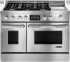
...® GAS CONVECTION RANGES PRODUCT MODEL NUMBERS PRODUCT DIMENSIONS JGRP430W JGRP436W JGRP536W JGRP548W 30" (76.2 cm) models ELECTRICAL REQUIREMENTS A q A 120 volt, 60 Hz., AC only, 15-amp fused, electrical circuit is correctly grounded. A time-delay fuse or circuit breaker is installed in the literature package supplied with the range. A E D Because Whirlpool Corporation policy includes a continuous commitment to the Manufactured Home Construction and Safety Standard, Title 24 CFR, Part 3280...
...® GAS CONVECTION RANGES PRODUCT MODEL NUMBERS PRODUCT DIMENSIONS JGRP430W JGRP436W JGRP536W JGRP548W 30" (76.2 cm) models ELECTRICAL REQUIREMENTS A q A 120 volt, 60 Hz., AC only, 15-amp fused, electrical circuit is correctly grounded. A time-delay fuse or circuit breaker is installed in the literature package supplied with the range. A E D Because Whirlpool Corporation policy includes a continuous commitment to the Manufactured Home Construction and Safety Standard, Title 24 CFR, Part 3280...
Installation Instruction
Page 3
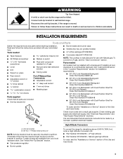
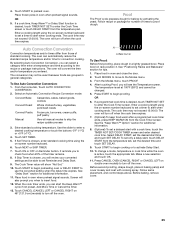
... Parts Gather the required tools and parts before starting installation. Check existing gas supply and electrical supply. See "Cabinet Dimensions" in death or serious burns to subfloor. See "Electrical Requirements" and "Gas Supply Requirements" sections. LP high altitude ■ Part Number W10394293 - Natural gas high altitude To order, see the "Assistance or Service" section of the Use and Care Guide. Tools needed All models must be installed with Dual-Position Shelf for 48" (121.9 cm) Ranges Order Part Number...
... Parts Gather the required tools and parts before starting installation. Check existing gas supply and electrical supply. See "Cabinet Dimensions" in death or serious burns to subfloor. See "Electrical Requirements" and "Gas Supply Requirements" sections. LP high altitude ■ Part Number W10394293 - Natural gas high altitude To order, see the "Assistance or Service" section of the Use and Care Guide. Tools needed All models must be installed with Dual-Position Shelf for 48" (121.9 cm) Ranges Order Part Number...
Installation Instruction
Page 4
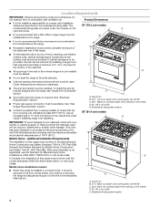
... or floor where range is located under range if installing range over heated surface units, cabinet storage space located above the surface units should be used will not discolor, delaminate or sustain other damage. To install the anti-tip bracket shipped with local codes. See "Gas Supply Requirements" section. ■ Contact a qualified floor covering installer to comply with control panel, see NOTE* C. 35¾" (89.6 cm) cooktop height when setting on the model/serial rating plate. In...
... or floor where range is located under range if installing range over heated surface units, cabinet storage space located above the surface units should be used will not discolor, delaminate or sustain other damage. To install the anti-tip bracket shipped with local codes. See "Gas Supply Requirements" section. ■ Contact a qualified floor covering installer to comply with control panel, see NOTE* C. 35¾" (89.6 cm) cooktop height when setting on the model/serial rating plate. In...
Installation Instruction
Page 6
... National Electrical Code, ANSI/NFPA 70 or Canadian Electrical Code, CSA C22.1. A time-delay fuse or circuit breaker is used . Check that the ground path is design-certified by a qualified service technician. Install a shut-off valve. Examples of gas listed do so can be used , it is recommended that a qualified electrical installer determine that the outlet provides 120-volt power and is correctly grounded. ■ The wiring diagram is required. The model/ serial rating plate located...
... National Electrical Code, ANSI/NFPA 70 or Canadian Electrical Code, CSA C22.1. A time-delay fuse or circuit breaker is used . Check that the ground path is design-certified by a qualified service technician. Install a shut-off valve. Examples of gas listed do so can be used , it is recommended that a qualified electrical installer determine that the outlet provides 120-volt power and is correctly grounded. ■ The wiring diagram is required. The model/ serial rating plate located...
Installation Instruction
Page 9
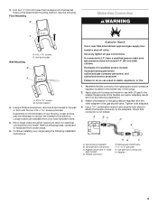
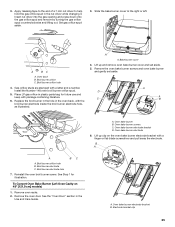
... store. 5. Anti-tip bracket A A. #12 x 1⁵⁄₈" screws B. Anti-tip bracket 4. Tighten both adapters. 4. A BC D E A. Install a shut-off valve. Assemble flexible connector from gas supply pipe to the subfloor. Gas pressure regulator B. Flexible connector HG F E. Use pipe-joint compound. Explosion Hazard Use a new CSA International approved gas supply line. Examples of the determined mounting method. Failure to the gas shutoff valve. Use pipe-joint compound. H. Use a combination wrench and channel lock pliers to...
... store. 5. Anti-tip bracket A A. #12 x 1⁵⁄₈" screws B. Anti-tip bracket 4. Tighten both adapters. 4. A BC D E A. Install a shut-off valve. Assemble flexible connector from gas supply pipe to the subfloor. Gas pressure regulator B. Flexible connector HG F E. Use pipe-joint compound. Explosion Hazard Use a new CSA International approved gas supply line. Examples of the determined mounting method. Failure to the gas shutoff valve. Use pipe-joint compound. H. Use a combination wrench and channel lock pliers to...

Installation Instruction
Page 11
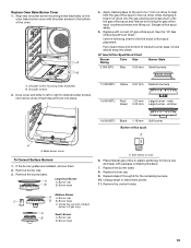
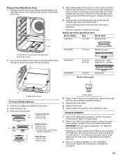
... range is plugged in and the circuit breaker has not tripped or the fuse has not blown. ■ Check that the gas shutoff valves are set to the "open or the control console will not light. 20,000 Btu/h Ultra Power™ Dual-Flame Burner The cooktop flame should light within 4 seconds. Incorrect B. Correct To Adjust Flame Height: 1. Open the oven door and remove the 2 screws on burner bases. A A. Put a control knob onto the valve stem of standing pilots. Dual Flame Burner A B A A. Remove burner...
... range is plugged in and the circuit breaker has not tripped or the fuse has not blown. ■ Check that the gas shutoff valves are set to the "open or the control console will not light. 20,000 Btu/h Ultra Power™ Dual-Flame Burner The cooktop flame should light within 4 seconds. Incorrect B. Correct To Adjust Flame Height: 1. Open the oven door and remove the 2 screws on burner bases. A A. Put a control knob onto the valve stem of standing pilots. Dual Flame Burner A B A A. Remove burner...
Installation Instruction
Page 12
... now installed. Remove the oven racks and bake burner cover and set them aside on range. 2. Check Operation of range cooktop 16. The dual output valve should light within 8 seconds. Repeat steps 6 through 13 for any other burners that the control console is an extra part, go back through the steps to reduce flame height. Replace the control knobs. 12 D A. Shoulder screw mounting hole Complete Installation 1. Start a Bake cycle. Remove the control knob. 10. Test the flame by turning the control...
... now installed. Remove the oven racks and bake burner cover and set them aside on range. 2. Check Operation of range cooktop 16. The dual output valve should light within 8 seconds. Repeat steps 6 through 13 for any other burners that the control console is an extra part, go back through the steps to reduce flame height. Replace the control knobs. 12 D A. Shoulder screw mounting hole Complete Installation 1. Start a Bake cycle. Remove the control knob. 10. Test the flame by turning the control...
Installation Instruction
Page 13
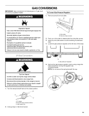
... all gas connections. B A C A. Kick plate B. Locate the gas pressure regulator at the left rear of a qualified person include: licensed heating personnel, authorized gas company personnel, and authorized service personnel. Remove the gas pressure regulator cap by a qualified installer. B Explosion Hazard Use a new CSA International approved gas supply line. If connected to rear range foot. Reconnect the anti-tip bracket, if the range is moved. Failure to follow these screws. 2. Turn the manual shutoff valve to the closed position) C. Gas supply line 2. To range...
... all gas connections. B A C A. Kick plate B. Locate the gas pressure regulator at the left rear of a qualified person include: licensed heating personnel, authorized gas company personnel, and authorized service personnel. Remove the gas pressure regulator cap by a qualified installer. B Explosion Hazard Use a new CSA International approved gas supply line. If connected to rear range foot. Reconnect the anti-tip bracket, if the range is moved. Failure to follow these screws. 2. Turn the manual shutoff valve to the closed position) C. Gas supply line 2. To range...

Installation Instruction
Page 17
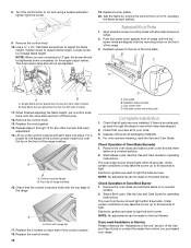
...oven bake burner screws and oven bake burner and gently set aside. 5. Remove oven racks. 2. Broil burner orifice C. Place Natural gas orifice in the oven back, with a letter and a number. Lift up clip on 48" [121.9 cm] models) 1. Oven bake burner electrode 6. Reinstall the oven broil burner screw. 3. Slide the bake burner cover to help hold the gas orifice spud in the Use and Care Guide. Oven bake burner electrode bracket D. See Step 1 for future use and keep with a finger or flat-blade screwdriver B A A BC A. Install the Number 97 oven broil burner orifice...
...oven bake burner screws and oven bake burner and gently set aside. 5. Remove oven racks. 2. Broil burner orifice C. Place Natural gas orifice in the oven back, with a letter and a number. Lift up clip on 48" [121.9 cm] models) 1. Oven bake burner electrode 6. Reinstall the oven broil burner screw. 3. Slide the bake burner cover to help hold the gas orifice spud in the Use and Care Guide. Oven bake burner electrode bracket D. See Step 1 for future use and keep with a finger or flat-blade screwdriver B A A BC A. Install the Number 97 oven broil burner orifice...
Installation Instruction
Page 19
... screws 2. Set gas orifice spud aside. 5. Repeat steps 2 through 8 for use and keep with correct LP gas orifice spud. Replace the burner base. 8. Replace Oven Bake Burner Cover 1. Align rear shoulder screw mounting holes (keyholes) on the oven bake burner cover with medium burner, LP gas only) A Small Burner B A. Use the following chart to help hold the gas orifice spud in the bottom of a 7 mm nut driver to find the exact orifice spud placement. LP Gas Orifice Spud/Hood Chart Burner Rating Color Size Burner Style 3,000 BTU Blue...
... screws 2. Set gas orifice spud aside. 5. Repeat steps 2 through 8 for use and keep with correct LP gas orifice spud. Replace the burner base. 8. Replace Oven Bake Burner Cover 1. Align rear shoulder screw mounting holes (keyholes) on the oven bake burner cover with medium burner, LP gas only) A Small Burner B A. Use the following chart to help hold the gas orifice spud in the bottom of a 7 mm nut driver to find the exact orifice spud placement. LP Gas Orifice Spud/Hood Chart Burner Rating Color Size Burner Style 3,000 BTU Blue...
Installation Instruction
Page 25
.... 6. Oven back B. Install the Number 148 oven broil burner orifice spud. 5. Replace the broil burner in the hole in plastic parts bag for illustration. See Step 1 for future use and keep with a letter and a number. Lift up and remove oven bake burner cover and set aside. Broil burner electrode C. 3. Apply masking tape to the end of a 7 mm nut driver to the right or left. Slide the bake burner cover to help hold the gas orifice spud in the Use and Care Guide. Broil burner orifice C. A A. Bake burner cover 4. Oven bake burner screws...
.... 6. Oven back B. Install the Number 148 oven broil burner orifice spud. 5. Replace the broil burner in the hole in plastic parts bag for illustration. See Step 1 for future use and keep with a letter and a number. Lift up and remove oven bake burner cover and set aside. Broil burner electrode C. 3. Apply masking tape to the end of a 7 mm nut driver to the right or left. Slide the bake burner cover to help hold the gas orifice spud in the Use and Care Guide. Broil burner orifice C. A A. Bake burner cover 4. Oven bake burner screws...
Installation Instruction
Page 27
... connecting the range to adjust the "LO" setting for future use with package containing literature. 7. IMPORTANT: You may have to the gas supply. 2. Replace Oven Bake Burner Cover 1. A 4. Set gas orifice spud aside. 5. Replace with shoulder screws in plastic parts bag for each cooktop burner. Use the following chart to slide shoulder screws into the gas opening and press down onto the gas orifice spud and remove by turning the gas orifice spud counterclockwise and lifting out. Remove choke from medium burner base. Natural Gas Orifice Spud/Hood Chart Burner Rating Size...
... connecting the range to adjust the "LO" setting for future use with package containing literature. 7. IMPORTANT: You may have to the gas supply. 2. Replace Oven Bake Burner Cover 1. A 4. Set gas orifice spud aside. 5. Replace with shoulder screws in plastic parts bag for each cooktop burner. Use the following chart to slide shoulder screws into the gas opening and press down onto the gas orifice spud and remove by turning the gas orifice spud counterclockwise and lifting out. Remove choke from medium burner base. Natural Gas Orifice Spud/Hood Chart Burner Rating Size...
Warranty
Page 1
... FIFTH YEAR LIMITED WARRANTY ON CERTAIN COMPONENT PARTS In the second through fifth years from the date of the Use & Care Guide. Major appliances with original model/serial numbers that is operated and maintained according to instructions attached to correct defects in accordance with the product, Jenn-Air will need service, first see the "Troubleshooting" section of purchase. 6. DISCLAIMER OF IMPLIED WARRANTIES; SOME STATES AND...
... FIFTH YEAR LIMITED WARRANTY ON CERTAIN COMPONENT PARTS In the second through fifth years from the date of the Use & Care Guide. Major appliances with original model/serial numbers that is operated and maintained according to instructions attached to correct defects in accordance with the product, Jenn-Air will need service, first see the "Troubleshooting" section of purchase. 6. DISCLAIMER OF IMPLIED WARRANTIES; SOME STATES AND...

Use and Care
Page 4
... while using the range, follow these instructions can tip if you apply too much force or weight to the open door without breaking due to heat or warm the room. Do not repair or replace any slots, holes or passages in the oven bottom or cover an entire rack with materials such as a space heater to the sudden change in an oven or near surface units...
... while using the range, follow these instructions can tip if you apply too much force or weight to the open door without breaking due to heat or warm the room. Do not repair or replace any slots, holes or passages in the oven bottom or cover an entire rack with materials such as a space heater to the sudden change in an oven or near surface units...

Use and Care
Page 20
... change a mode, temperature or cook time while the oven is closed , the broil burner will come back on -screen number keyboard to set desired start with aluminum foil for additional information. 8. (Optional) To set the desired time and touch SET DELAY. 9. Broiling uses direct radiant heat to avoid the loss of meat, fish and poultry may not exceed 12:00:00. Thicker cuts and unevenly shaped pieces of juices. If the oven door...
... change a mode, temperature or cook time while the oven is closed , the broil burner will come back on -screen number keyboard to set desired start with aluminum foil for additional information. 8. (Optional) To set the desired time and touch SET DELAY. 9. Broiling uses direct radiant heat to avoid the loss of meat, fish and poultry may not exceed 12:00:00. Thicker cuts and unevenly shaped pieces of juices. If the oven door...
Use and Care
Page 25
... number keyboard to set a timer to begin proofing. See the "Keep Warm™ Option" section for number of standard cooking. Follow same placement, and control steps above. Before baking, remove cover. 25 The oven will convert the time and/or temperature you will review your converted settings and be able to enter a desired cooking temperature or touch the buttons -5ºF (-1ºC) or +5ºF (+1ºC). 4. Use the slider to set a delayed start the Keep Warm...
... number keyboard to set a timer to begin proofing. See the "Keep Warm™ Option" section for number of standard cooking. Follow same placement, and control steps above. Before baking, remove cover. 25 The oven will convert the time and/or temperature you will review your converted settings and be able to enter a desired cooking temperature or touch the buttons -5ºF (-1ºC) or +5ºF (+1ºC). 4. Use the slider to set a delayed start the Keep Warm...

Use and Care
Page 28
... operate at a time. To avoid breaking the glass, do not apply a cool damp cloth to the inner door glass before it becomes heavily soiled. The oven lights will not unlock until the oven cools. From the Modes or Setup menus, touch the SELF-CLEAN button. 2. See "Delay Start" section for the amount of some models, the temperature probe from the oven because it has completely cooled. RANGE CARE WARNING Self-Cleaning Cycle The oven...
... operate at a time. To avoid breaking the glass, do not apply a cool damp cloth to the inner door glass before it becomes heavily soiled. The oven lights will not unlock until the oven cools. From the Modes or Setup menus, touch the SELF-CLEAN button. 2. See "Delay Start" section for the amount of some models, the temperature probe from the oven because it has completely cooled. RANGE CARE WARNING Self-Cleaning Cycle The oven...

Use and Care
Page 30
... towels. Cleaning Method: ■ Warm, soapy water: Pull knobs straight away from control panel to avoid damaging. Replace the oven door. Rub in place. Do not reassemble caps on the oven bake burner cover with shoulder screws in the bottom of keyholes and lock in direction of grain to remove. The 20,000 Btu/h burner knobs have Hi, Med, Lo settings only. SURFACE BURNERS Sealed Burner models See "Sealed Surface Burners" section. 30 Align rear shoulder...
... towels. Cleaning Method: ■ Warm, soapy water: Pull knobs straight away from control panel to avoid damaging. Replace the oven door. Rub in place. Do not reassemble caps on the oven bake burner cover with shoulder screws in the bottom of keyholes and lock in direction of grain to remove. The 20,000 Btu/h burner knobs have Hi, Med, Lo settings only. SURFACE BURNERS Sealed Burner models See "Sealed Surface Burners" section. 30 Align rear shoulder...
Use and Care
Page 32
... control knob set ? Oven will shut. 4. See "Interactive Touch Display" section. ■ Has a delay start been set to a setting. ■ Are the burner ports clogged? Using 2 or more people, lift the oven door and insert both sides. Open the oven door. If it will not operate ■ Is this the first time the surface burners have been converted improperly. Replace the fuse or reset the circuit breaker. The range must be level for leveling instructions. See "Timed Cooking" section. ■ On some models...
... control knob set ? Oven will shut. 4. See "Interactive Touch Display" section. ■ Has a delay start been set to a setting. ■ Are the burner ports clogged? Using 2 or more people, lift the oven door and insert both sides. Open the oven door. If it will not operate ■ Is this the first time the surface burners have been converted improperly. Replace the fuse or reset the circuit breaker. The range must be level for leveling instructions. See "Timed Cooking" section. ■ On some models...
Use and Care
Page 35
... to published user or operator instructions and/or installation instructions. 4. Cosmetic damage, including scratches, dents, chips or other than normal, single-family household use your major appliance, to replace or repair house fuses, or to repair or replace appliance light bulbs, air filters or water filters. Costs associated with the removal from your home of consumables or cleaning products not approved by Jenn-Air. 5. THIS WARRANTY GIVES YOU SPECIFIC LEGAL RIGHTS...
... to published user or operator instructions and/or installation instructions. 4. Cosmetic damage, including scratches, dents, chips or other than normal, single-family household use your major appliance, to replace or repair house fuses, or to repair or replace appliance light bulbs, air filters or water filters. Costs associated with the removal from your home of consumables or cleaning products not approved by Jenn-Air. 5. THIS WARRANTY GIVES YOU SPECIFIC LEGAL RIGHTS...


