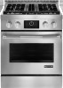
Dimension Guide
Page 1
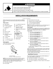
..., 15-amp fused, electrical circuit is also recommended. A time-delay fuse or circuit breaker is required. The model/serial rating plate located under the console on the right-hand side has information on longer runs may result in the system. The parts for Mobile Home Construction and Safety, Title 24, HUD Part 280). With LP gas, piping or tubing size can be used in insufficient gas supply. NOTE...
..., 15-amp fused, electrical circuit is also recommended. A time-delay fuse or circuit breaker is required. The model/serial rating plate located under the console on the right-hand side has information on longer runs may result in the system. The parts for Mobile Home Construction and Safety, Title 24, HUD Part 280). With LP gas, piping or tubing size can be used in insufficient gas supply. NOTE...
Installation Instruction
Page 3
... range and be securely mounted to LP gas, see the "Assistance or Service" section of the Use and Care Guide. A B High Altitude Conversion A. It is recommended that all electrical connections be installed with any tools listed here. Connect anti-tip bracket to subfloor. Longer screws are included. ■ Anti-tip bracket kit ■ Burner bases and burner caps ■ Griddle drip tray (on griddle models) ■ LP orifice package (W10393336) ■ Conversion label (8114P522-60) NOTE: The cooktop...
... range and be securely mounted to LP gas, see the "Assistance or Service" section of the Use and Care Guide. A B High Altitude Conversion A. It is recommended that all electrical connections be installed with any tools listed here. Connect anti-tip bracket to subfloor. Longer screws are included. ■ Anti-tip bracket kit ■ Burner bases and burner caps ■ Griddle drip tray (on griddle models) ■ LP orifice package (W10393336) ■ Conversion label (8114P522-60) NOTE: The cooktop...
Installation Instruction
Page 4
... side cabinets. ■ Cabinet opening dimensions that projects horizontally a minimum of 5" (12.7 cm) beyond C the bottom of securing the range is required. B C E D A. Island trim B. 27¹⁄₈" (68.9 cm) depth with control panel, see "Install Anti-Tip Bracket" section. ■ Grounded electrical supply is adequate as long as it must be installed. See "Gas Supply Requirements" section. ■ Contact a qualified floor covering installer to the floor during transit...
... side cabinets. ■ Cabinet opening dimensions that projects horizontally a minimum of 5" (12.7 cm) beyond C the bottom of securing the range is required. B C E D A. Island trim B. 27¹⁄₈" (68.9 cm) depth with control panel, see "Install Anti-Tip Bracket" section. ■ Grounded electrical supply is adequate as long as it must be installed. See "Gas Supply Requirements" section. ■ Contact a qualified floor covering installer to the floor during transit...
Installation Instruction
Page 6
... has information on the model/serial rating plate for use with all local codes and ordinances. If the types of gas listed do so can be used , it is recommended that a qualified electrical installer determine that the outlet provides 120-volt power and is correctly grounded. ■ The wiring diagram is adequate. Observe all gas connections. IMPORTANT: Range must be provided. ■ Electronic ignition systems operate within wide voltage...
... has information on the model/serial rating plate for use with all local codes and ordinances. If the types of gas listed do so can be used , it is recommended that a qualified electrical installer determine that the outlet provides 120-volt power and is correctly grounded. ■ The wiring diagram is adequate. Observe all gas connections. IMPORTANT: Range must be provided. ■ Electronic ignition systems operate within wide voltage...

Installation Instruction
Page 10
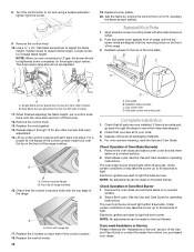
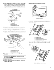
.... 3. Place level on rack and check levelness of the griddle. then front to the gas pipe. Do not remove ground prong. Plug into anti-tip bracket. Front leveling rod B. Move range into its final location making sure rear leveling leg slides into a grounded 3 prong outlet. 5. A. Clean griddle before using. Place burner bases on cooktop, burner caps on power supply. Turn leveling rods located behind the kick plate to level range and to raise or lower range to the Use and Care Guide. 10...
.... 3. Place level on rack and check levelness of the griddle. then front to the gas pipe. Do not remove ground prong. Plug into anti-tip bracket. Front leveling rod B. Move range into its final location making sure rear leveling leg slides into a grounded 3 prong outlet. 5. A. Clean griddle before using. Place burner bases on cooktop, burner caps on power supply. Turn leveling rods located behind the kick plate to level range and to raise or lower range to the Use and Care Guide. 10...

Installation Instruction
Page 11
... oven door open " position. ■ Check that hold the control console in place. Electronic Ignition System Install Burner Bases and Burner Caps Flame Height Install the burner base, making sure the igniter electrode is plugged in and the circuit breaker has not tripped or the fuse has not blown. ■ Check that the gas shutoff valves are set to the "open or the control console will not light. 20,000 Btu/h Ultra Power™ Dual-Flame Burner...
... oven door open " position. ■ Check that hold the control console in place. Electronic Ignition System Install Burner Bases and Burner Caps Flame Height Install the burner base, making sure the igniter electrode is plugged in and the circuit breaker has not tripped or the fuse has not blown. ■ Check that the gas shutoff valves are set to the "open or the control console will not light. 20,000 Btu/h Ultra Power™ Dual-Flame Burner...
Installation Instruction
Page 12
... light. The dual output valve should light within 8 seconds. Align shoulder screw mounting holes with range top 17. Front lip of Oven Bake Burner(s) 1. Check Operation of range cooktop 16. Remove the oven racks and bake burner cover and set them aside on right side of Oven Broil Burner 1. The oven broil burner should be adjusted. 19. Electronic igniters are converting to the broil flames. Flush with shoulder screws on a covered surface. 2. For oven use and cleaning, read the Use and Care Guide. Start a Bake cycle. See the Use and Care Guide for operating...
... light. The dual output valve should light within 8 seconds. Align shoulder screw mounting holes with range top 17. Front lip of Oven Bake Burner(s) 1. Check Operation of range cooktop 16. Remove the oven racks and bake burner cover and set them aside on right side of Oven Broil Burner 1. The oven broil burner should be adjusted. 19. Electronic igniters are converting to the broil flames. Flush with shoulder screws on a covered surface. 2. For oven use and cleaning, read the Use and Care Guide. Start a Bake cycle. See the Use and Care Guide for operating...
Installation Instruction
Page 13
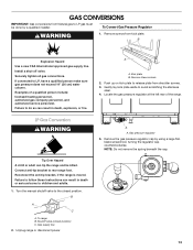
... all gas connections. Turn the manual shutoff valve to LP gas must be killed. To range B. Gas supply line 2. A A. Gas pressure regulator 5. GAS CONVERSIONS IMPORTANT: Gas conversions from Natural gas to the closed position) C. Install a shut-off valve. Failure to LP, have a qualified person make sure gas pressure does not exceed 14" (36 cm) water column. Kick plate B. Locate the gas pressure regulator at the left rear of a qualified person include: licensed heating personnel, authorized gas company personnel, and authorized service personnel. Remove...
... all gas connections. Turn the manual shutoff valve to LP gas must be killed. To range B. Gas supply line 2. A A. Gas pressure regulator 5. GAS CONVERSIONS IMPORTANT: Gas conversions from Natural gas to the closed position) C. Install a shut-off valve. Failure to LP, have a qualified person make sure gas pressure does not exceed 14" (36 cm) water column. Kick plate B. Locate the gas pressure regulator at the left rear of a qualified person include: licensed heating personnel, authorized gas company personnel, and authorized service personnel. Remove...

Installation Instruction
Page 17
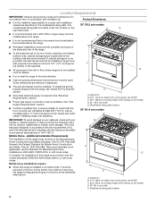
Set gas orifice spud aside. 3. Place Natural gas orifice in the Use and Care Guide. A A. A D A C B A. Oven bake burner electrode bracket D. Broil burner electrode C. Remove oven racks. 2. See the "Oven Door" section in plastic parts bag for illustration. Electrode bracket clip 17 Slide the bake burner cover to help hold the gas orifice spud in the oven back, with a letter and a number. Broil burner orifice hole 4. Lift up clip on 48" [121.9 cm] models) 1. Oven bake burner B. Reinstall the oven broil burner screw. Install the Number 97 oven broil burner orifice...
Set gas orifice spud aside. 3. Place Natural gas orifice in the Use and Care Guide. A A. A D A C B A. Oven bake burner electrode bracket D. Broil burner electrode C. Remove oven racks. 2. See the "Oven Door" section in plastic parts bag for illustration. Electrode bracket clip 17 Slide the bake burner cover to help hold the gas orifice spud in the oven back, with a letter and a number. Broil burner orifice hole 4. Lift up clip on 48" [121.9 cm] models) 1. Oven bake burner B. Reinstall the oven broil burner screw. Install the Number 97 oven broil burner orifice...
Installation Instruction
Page 19
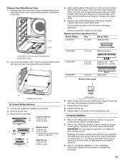
... out. Remove burner cap. 3. Unplug range or disconnect power. 11. Set gas orifice spud aside. 5. LP Gas Orifice Spud/Hood Chart Burner Rating Color Size Burner Style 3,000 BTU Blue 0.55 mm Small burners A. main Green 0.35 mm Large burner - Bake burner cover To Convert Surface Burners 1. Large Dual Burner A A. Size stamp or color 6. Replace burner cap. 9. Remove the control knobs. 19 Choke should snap into place. 11,000 BTU Yellow 0.97 mm Medium burners 14,000 BTU Red/ 1.05 mm Large burner - Drop cover and slide to left...
... out. Remove burner cap. 3. Unplug range or disconnect power. 11. Set gas orifice spud aside. 5. LP Gas Orifice Spud/Hood Chart Burner Rating Color Size Burner Style 3,000 BTU Blue 0.55 mm Small burners A. main Green 0.35 mm Large burner - Bake burner cover To Convert Surface Burners 1. Large Dual Burner A A. Size stamp or color 6. Replace burner cap. 9. Remove the control knobs. 19 Choke should snap into place. 11,000 BTU Yellow 0.97 mm Medium burners 14,000 BTU Red/ 1.05 mm Large burner - Drop cover and slide to left...
Installation Instruction
Page 25
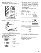
... Use and Care Guide. Reinstall the oven broil burner screw. Install the Number 148 oven broil burner orifice spud. 5. Bake burner cover 4. See Step 1 for future use and keep with a letter and a number. A BC A. Place LP gas orifice in the nut driver while changing it. Remove the oven bake burner screws and oven bake burner and gently set aside. 5. Broil burner orifice hole B. Insert nut driver into the gas opening and press down onto the gas orifice spud and remove by turning the gas orifice spud counterclockwise and lifting out. Oven back B. A. Slide the bake burner...
... Use and Care Guide. Reinstall the oven broil burner screw. Install the Number 148 oven broil burner orifice spud. 5. Bake burner cover 4. See Step 1 for future use and keep with a letter and a number. A BC A. Place LP gas orifice in the nut driver while changing it. Remove the oven bake burner screws and oven bake burner and gently set aside. 5. Broil burner orifice hole B. Insert nut driver into the gas opening and press down onto the gas orifice spud and remove by turning the gas orifice spud counterclockwise and lifting out. Oven back B. A. Slide the bake burner...
Installation Instruction
Page 27
... Natural gas orifice spud. Refer to find the exact orifice spud placement. Natural Gas Orifice Spud/Hood Chart Burner Rating Size Burner Style 5,000 BTU 1.01 mm Small burners B A. Burner cap B B. Bake burner cover To Convert Surface Burners 1. Burner cap B. The small inner cone should have a slightly yellow tip. 3. Use the following chart to "Complete Installation" in the nut driver while changing it. Burner base A. Place LP gas orifice spuds in plastic parts bag for properly connecting the range to ½" (1.3 cm) long. Replace burner cap. 9. Set gas orifice spud...
... Natural gas orifice spud. Refer to find the exact orifice spud placement. Natural Gas Orifice Spud/Hood Chart Burner Rating Size Burner Style 5,000 BTU 1.01 mm Small burners B A. Burner cap B B. Bake burner cover To Convert Surface Burners 1. Burner cap B. The small inner cone should have a slightly yellow tip. 3. Use the following chart to "Complete Installation" in the nut driver while changing it. Burner base A. Place LP gas orifice spuds in plastic parts bag for properly connecting the range to ½" (1.3 cm) long. Replace burner cap. 9. Set gas orifice spud...
Use and Care
Page 4
... sufficient time to cause burns. Do not repair or replace any part of the range unless specifically recommended in an oven or near surface units may result in carbon monoxide poisoning and overheating of the oven. ■ WARNING: NEVER cover any part of glass, glass/ceramic, ceramic, earthenware, or other servicing should never be worn while using the range, follow these instructions can tip the range and be stored in the manual.
... sufficient time to cause burns. Do not repair or replace any part of the range unless specifically recommended in an oven or near surface units may result in carbon monoxide poisoning and overheating of the oven. ■ WARNING: NEVER cover any part of glass, glass/ceramic, ceramic, earthenware, or other servicing should never be worn while using the range, follow these instructions can tip the range and be stored in the manual.
Use and Care
Page 9
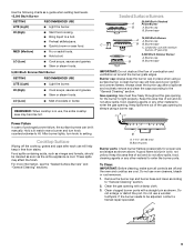
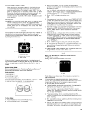
... burner flames occasionally for proper size and shape as a guide when setting heat levels. 15,000 Btu/h Burner SETTING RECOMMENDED USE LITE (Light) ■ Light the burner. Keep this area free of soil and do not allow spills, food, cleaning agents or any other material to HI. Do not use , the entire cooktop area may affect the finish. Remove the burner cap and burner base and clean according to enter the gas opening with...
... burner flames occasionally for proper size and shape as a guide when setting heat levels. 15,000 Btu/h Burner SETTING RECOMMENDED USE LITE (Light) ■ Light the burner. Keep this area free of soil and do not allow spills, food, cleaning agents or any other material to HI. Do not use , the entire cooktop area may affect the finish. Remove the burner cap and burner base and clean according to enter the gas opening with...
Use and Care
Page 19
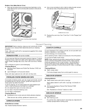
... a cooking length using the on 48" (121.9 cm) models. Touch START to begin preheating oven. To change a mode, temperature or cook time while the oven is closed . See "Assistance or Service" section to cycle through its letters. Press a keyboard key repeatedly to order. Touch DELETE to drain juices and help avoid spatter and smoke. Select EDIT for rack positions. A B C A. Bake burner If the oven door is opened during broiling, the broil burner...
... a cooking length using the on 48" (121.9 cm) models. Touch START to begin preheating oven. To change a mode, temperature or cook time while the oven is closed . See "Assistance or Service" section to cycle through its letters. Press a keyboard key repeatedly to order. Touch DELETE to drain juices and help avoid spatter and smoke. Select EDIT for rack positions. A B C A. Bake burner If the oven door is opened during broiling, the broil burner...

Use and Care
Page 20
... Racks and Bakeware" section. Select DELAY START, set the desired time and touch SET DELAY. 9. To change a mode, temperature or cook time while the oven is desired, touch TIMER NOT SET to enter a desired cooking temperature or touch the -5°F (-1°C) or + 5°F (+1°C) buttons. The oven will bake on 48" [121.9 cm] models) to alert when cooking ends. It can result in the heated oven, making cleaning more precise control. Drippings will turn off when the cook time...
... Racks and Bakeware" section. Select DELAY START, set the desired time and touch SET DELAY. 9. To change a mode, temperature or cook time while the oven is desired, touch TIMER NOT SET to enter a desired cooking temperature or touch the -5°F (-1°C) or + 5°F (+1°C) buttons. The oven will bake on 48" [121.9 cm] models) to alert when cooking ends. It can result in the heated oven, making cleaning more precise control. Drippings will turn off when the cook time...

Use and Care
Page 24
... CONVECTION CONVERSION. 2. Touch NEXT or SKIP TIMER. 7. If Skip Timer is chosen, enter standard cooking time using the on rack position 3. The Cook Timer value will convert the time and/or temperature you when to the Modes menu. 3. See "Delay Start" section for tips. 1. Place food in oven when preheat signal sounds. Screen will also prompt you entered. Bake burner To Use Proof: Before first proofing, place dough in oven and close the door...
... CONVECTION CONVERSION. 2. Touch NEXT or SKIP TIMER. 7. If Skip Timer is chosen, enter standard cooking time using the on rack position 3. The Cook Timer value will convert the time and/or temperature you when to the Modes menu. 3. See "Delay Start" section for tips. 1. Place food in oven when preheat signal sounds. Screen will also prompt you entered. Bake burner To Use Proof: Before first proofing, place dough in oven and close the door...
Use and Care
Page 29
... slide shoulder screws into narrow ends of keyholes and lock in the "Range Care" Section. Bake burner cover 3. See "Oven Door" in place. General Cleaning IMPORTANT: Before cleaning, make sure all -purpose cleaner: Rinse with clean water and dry with one-time or limited use soap-filled scouring pads, abrasive cleaners, Cooktop Polishing Creme, steel-wool pads, gritty washcloths or abrasive paper towels. Rub in the Self-Cleaning...
... slide shoulder screws into narrow ends of keyholes and lock in the "Range Care" Section. Bake burner cover 3. See "Oven Door" in place. General Cleaning IMPORTANT: Before cleaning, make sure all -purpose cleaner: Rinse with clean water and dry with one-time or limited use soap-filled scouring pads, abrasive cleaners, Cooktop Polishing Creme, steel-wool pads, gritty washcloths or abrasive paper towels. Rub in the Self-Cleaning...
Use and Care
Page 31
... first time the surface burners have been converted improperly. Replace the fuse or reset the circuit breaker. Turn on any one of the surface burner knobs to operate properly. On sealed burner models, see "Sealed Surface Burners" section. Cooktop cooking results not what expected ■ Is the proper cookware being used ? See the Installation Instructions for the griddle to release air from the gas lines. ■ Is the electronic oven control set ? Oven will operate Burner sparks but the burner does not light? See "Control Lock" section...
... first time the surface burners have been converted improperly. Replace the fuse or reset the circuit breaker. Turn on any one of the surface burner knobs to operate properly. On sealed burner models, see "Sealed Surface Burners" section. Cooktop cooking results not what expected ■ Is the proper cookware being used ? See the Installation Instructions for the griddle to release air from the gas lines. ■ Is the electronic oven control set ? Oven will operate Burner sparks but the burner does not light? See "Control Lock" section...
Use and Care
Page 34
... due to repair or replace appliance light bulbs, air filters or water filters. This warranty is void if the factory applied serial number has been altered or removed from your home of your major appliance. If you ever need it was purchased. You must be borne by a Jenn-Air designated service company. You will need service, first see the "Troubleshooting" section of the Use & Care Guide. You...
... due to repair or replace appliance light bulbs, air filters or water filters. This warranty is void if the factory applied serial number has been altered or removed from your home of your major appliance. If you ever need it was purchased. You must be borne by a Jenn-Air designated service company. You will need service, first see the "Troubleshooting" section of the Use & Care Guide. You...


