Instruction Manual
Page 1
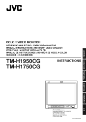
... DEUTSCH ENGLISH COLOR VIDEO MONITOR BEDIENUNGSANLEITUNG : FARB-VIDEO-MONITOR MANUEL D'INSTRUCTIONS : MONITEUR VIDÉO COULEUR ISTRUZIONI : MONITOR VIDEO A COLORI MANUAL DE INSTRUCCIONES : MONITOR DE VIDEO A COLOR j TM-H1950CG TM-H1750CG INSTRUCTIONS ʕ˖ TM-H1950CG CHROMA CONTRAST VOLUME/SELECT PHASE BRIGHT MENU UNDER COLOR BLUE SCAN OFF CHECK ASPECT A B C SLOT D INPUT SELECT POWER (TM-H1950CG...
... DEUTSCH ENGLISH COLOR VIDEO MONITOR BEDIENUNGSANLEITUNG : FARB-VIDEO-MONITOR MANUEL D'INSTRUCTIONS : MONITEUR VIDÉO COULEUR ISTRUZIONI : MONITOR VIDEO A COLORI MANUAL DE INSTRUCCIONES : MONITOR DE VIDEO A COLOR j TM-H1950CG TM-H1750CG INSTRUCTIONS ʕ˖ TM-H1950CG CHROMA CONTRAST VOLUME/SELECT PHASE BRIGHT MENU UNDER COLOR BLUE SCAN OFF CHECK ASPECT A B C SLOT D INPUT SELECT POWER (TM-H1950CG...

Instruction Manual
Page 3
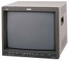
Before using it, read and follow all instructions carefully to take full advantage of the monitor's capabilities. ENGLISH INSTRUCTIONS COLOR VIDEO MONITOR TM-H1950CG TM-H1750CG Thank you for purchasing this JVC color video monitor.
Before using it, read and follow all instructions carefully to take full advantage of the monitor's capabilities. ENGLISH INSTRUCTIONS COLOR VIDEO MONITOR TM-H1950CG TM-H1750CG Thank you for purchasing this JVC color video monitor.
Instruction Manual
Page 4
...; When dust accumulates on , the user is connected. - Ask qualified service personnel to dispose of the cabinet. When servicing the monitor, consult qualified service personnel. This equipment generates, uses and can be regulated in your electrician. in badly ventilated places, - in extremely...regarding electromagnetic compatibility and electrical safety. Disposal of these materials may result in x-ray emission of considerable dose. in : JVC Technical Services Europe GmbH Postfach 10 05 52 61145 Friedberg Germany FCC INFORMATION (U.S.A. if the unit has been dropped or the...
...; When dust accumulates on , the user is connected. - Ask qualified service personnel to dispose of the cabinet. When servicing the monitor, consult qualified service personnel. This equipment generates, uses and can be regulated in your electrician. in badly ventilated places, - in extremely...regarding electromagnetic compatibility and electrical safety. Disposal of these materials may result in x-ray emission of considerable dose. in : JVC Technical Services Europe GmbH Postfach 10 05 52 61145 Friedberg Germany FCC INFORMATION (U.S.A. if the unit has been dropped or the...
Instruction Manual
Page 5
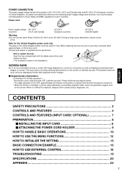
... power supply voltage rating of this product is difficult to eradicate, degauss from the time the power is turned on. * When the monitor is installed, it is AC 120 V (For U.S.A. and Canada AC 230 V European countries AC 230 V United Kingdom Warning: &#... This problem does not occur as far as for monitor operation = This monitor uses a high precision CRT (cathode ray tube). ENGLISH CONTENTS SAFETY PRECAUTIONS 2 CONTROLS AND FEATURES 4 CONTROLS AND FEATURES (INPUT CARD: OPTIONAL 7 PREPARATION 8 Ⅵ INSTALLING THE INPUT CARD 8 Ⅵ ATTACHING THE POWER CORD HOLDER 9 ...
... power supply voltage rating of this product is difficult to eradicate, degauss from the time the power is turned on. * When the monitor is installed, it is AC 120 V (For U.S.A. and Canada AC 230 V European countries AC 230 V United Kingdom Warning: &#... This problem does not occur as far as for monitor operation = This monitor uses a high precision CRT (cathode ray tube). ENGLISH CONTENTS SAFETY PRECAUTIONS 2 CONTROLS AND FEATURES 4 CONTROLS AND FEATURES (INPUT CARD: OPTIONAL 7 PREPARATION 8 Ⅵ INSTALLING THE INPUT CARD 8 Ⅵ ATTACHING THE POWER CORD HOLDER 9 ...
Instruction Manual
Page 6
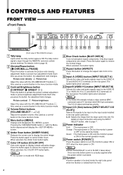
... Cuts red and green signal components. C, D: Selects the image from 4:3 to 16:9. 10 Input A (VIDEO) button [INPUT SELECT A] Selects the video and audio signals input to be input via the input cards installed in the stand-by mode). Only blue signal components are shown. Each time you press the... priority. 12 Input C/D (Slot) buttons [INPUT SELECT C/D (SLOT)] Selects the signals to the VIDEO A * and AUDIO A q terminals on the rear panel. Note: ● This function is ON. Orange : The main power is ON, but the monitor's power is OFF (in the rear panel card slots. Each time...
... Cuts red and green signal components. C, D: Selects the image from 4:3 to 16:9. 10 Input A (VIDEO) button [INPUT SELECT A] Selects the video and audio signals input to be input via the input cards installed in the stand-by mode). Only blue signal components are shown. Each time you press the... priority. 12 Input C/D (Slot) buttons [INPUT SELECT C/D (SLOT)] Selects the signals to the VIDEO A * and AUDIO A q terminals on the rear panel. Note: ● This function is ON. Orange : The main power is ON, but the monitor's power is OFF (in the rear panel card slots. Each time...
Instruction Manual
Page 7
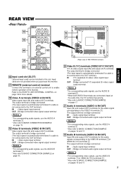
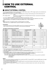
...video signals, use the AUDIO B terminals w. * When both VIDEO B terminals are not provided when you purchase this monitor. 17 REMOTE (external control) terminal Connect this slot. Input cards are connected (input) at the same time, the Y/C terminal has priority. * Also refer to BASIC CONNECTION EXAMPLE on page 18 for...VIDEO A 18 IN OUT VIDEO B 19 IN OUT 20 IN Y/C OUT AUDIO A 21 IN OUT AUDIO B 22 IN OUT 16 Input card slot (SLOT) Optional input cards can be installed in this terminal to an external control unit to the HOW TO USE EXTERNAL CONTROL on page 17. 21 Audio A ...
...video signals, use the AUDIO B terminals w. * When both VIDEO B terminals are not provided when you purchase this monitor. 17 REMOTE (external control) terminal Connect this slot. Input cards are connected (input) at the same time, the Y/C terminal has priority. * Also refer to BASIC CONNECTION EXAMPLE on page 18 for...VIDEO A 18 IN OUT VIDEO B 19 IN OUT 20 IN Y/C OUT AUDIO A 21 IN OUT AUDIO B 22 IN OUT 16 Input card slot (SLOT) Optional input cards can be installed in this terminal to an external control unit to the HOW TO USE EXTERNAL CONTROL on page 17. 21 Audio A ...

Instruction Manual
Page 8
...cables are provided (one power cable. I : ON ⅜ : OFF 24 AC inlet [AC IN] Power input connector. When the main power is appropriate for the UK). If none of TM-H1950CG shown) 24 23 23 ...Main power switch Press the switch to use in orange and the monitor enters the stand-by mode. CONTROLS AND FEATURES (cont'd) REAR VIEW To AC outlet (120 V AC,...230 V AC, 50 Hz/60 Hz) 25 For U.S.A. Caution: In North America (USA and Canada), this monitor comes with one for use the power cable that is ON, the power indicator on the front panel lights in...
...cables are provided (one power cable. I : ON ⅜ : OFF 24 AC inlet [AC IN] Power input connector. When the main power is appropriate for the UK). If none of TM-H1950CG shown) 24 23 23 ...Main power switch Press the switch to use in orange and the monitor enters the stand-by mode. CONTROLS AND FEATURES (cont'd) REAR VIEW To AC outlet (120 V AC,...230 V AC, 50 Hz/60 Hz) 25 For U.S.A. Caution: In North America (USA and Canada), this monitor comes with one for use the power cable that is ON, the power indicator on the front panel lights in...
Instruction Manual
Page 9
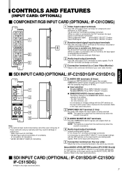
... from this terminal only when the monitor is connected to the connection terminal in damage or malfunction. *Video input card (IF-C01PNG) *HD-SDI input card (IF-C01HSDG, IF-C12HSDG, IF-C21HSDG, IF-C51HSDG) *HD/SD SDI INPUT CARD (IF-C61HSDG) 1 E.AUDIO SDI...select INPUT SELECT C and change settings with the DIP switches on the input card to the OUT terminal, the input signal is automatically terminated.) G on the input card to select INPUT SELECT C and change settings with RGB input only. CONTROLS AND FEATURES (INPUT CARD: OPTIONAL) Ⅵ COMPONENT/RGB INPUT CARD (OPTIONAL:...
... from this terminal only when the monitor is connected to the connection terminal in damage or malfunction. *Video input card (IF-C01PNG) *HD-SDI input card (IF-C01HSDG, IF-C12HSDG, IF-C21HSDG, IF-C51HSDG) *HD/SD SDI INPUT CARD (IF-C61HSDG) 1 E.AUDIO SDI...select INPUT SELECT C and change settings with the DIP switches on the input card to the OUT terminal, the input signal is automatically terminated.) G on the input card to select INPUT SELECT C and change settings with RGB input only. CONTROLS AND FEATURES (INPUT CARD: OPTIONAL) Ⅵ COMPONENT/RGB INPUT CARD (OPTIONAL:...
Instruction Manual
Page 10
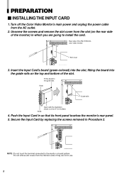
...terminal connected to the guide rails. Secure the Input Card by replacing the screws removed in which you are not in so that its front panel touches the monitor's rear panel. 5. Push the Input Card in use. 8 PREPARATION Ⅵ INSTALLING THE INPUT CARD 1. Do not remove slot covers from the ...AC outlet. 2. Fit the board to the monitor or board pattern. Knob REMOTE SLOT VIDEO A IN ...
...terminal connected to the guide rails. Secure the Input Card by replacing the screws removed in which you are not in so that its front panel touches the monitor's rear panel. 5. Push the Input Card in use. 8 PREPARATION Ⅵ INSTALLING THE INPUT CARD 1. Do not remove slot covers from the ...AC outlet. 2. Fit the board to the monitor or board pattern. Knob REMOTE SLOT VIDEO A IN ...

Instruction Manual
Page 11
... CORD HOLDER The provided Power Cord Holder prevents the AC power cord from being attached to a different position. The Power Cord Holder consists of the monitor with the case. Attach the Power Cord Holder case to the AC inlet on the back of two parts; Hold until it clicks. Caution: Use...
... CORD HOLDER The provided Power Cord Holder prevents the AC power cord from being attached to a different position. The Power Cord Holder consists of the monitor with the case. Attach the Power Cord Holder case to the AC inlet on the back of two parts; Hold until it clicks. Caution: Use...
Instruction Manual
Page 12
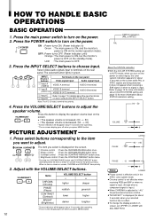
...Refer to turn on the rear panel. POWER ON : Power turns ON. (Power indicator: lit) Green : The main power is ON, and the monitor's power is ON (in the NTSC color system mode. ● Chroma control is not effective when receiving RGB and B/W or when no item is OFF...no signal is OFF. 3. It does not appear when receiving a B/W signal or when no effect. ● To change the display position on each card and the INPUT SELECT button. Note: The Y/C (S-video) terminal has priority. 4. HOW TO HANDLE BASIC OPERATIONS BASIC OPERATION 1. Press the main power switch to page ...
...Refer to turn on the rear panel. POWER ON : Power turns ON. (Power indicator: lit) Green : The main power is ON, and the monitor's power is ON (in the NTSC color system mode. ● Chroma control is not effective when receiving RGB and B/W or when no item is OFF...no signal is OFF. 3. It does not appear when receiving a B/W signal or when no effect. ● To change the display position on each card and the INPUT SELECT button. Note: The Y/C (S-video) terminal has priority. 4. HOW TO HANDLE BASIC OPERATIONS BASIC OPERATION 1. Press the main power switch to page ...
Instruction Manual
Page 14
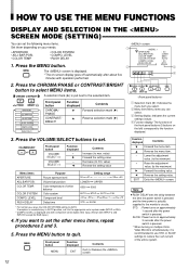
...SELECT buttons to quit. COLOR TEMP. If you can set the following menu items. screen Set them depending on multiple ColorVideo Monitors simultaneously, it to the appropriate color system mode (NTSC or PAL). * COMPO. MENU Front panel button MENU Function displayed EXIT...RUSH DELAY : STD. 2 3 MENU The screen is displayed. * The on approximately 1 second after about five EXIT 4 minutes with INPUT-C and INPUT-D except for RGB input.) 4. Press the CHROMA/PHASE or CONTRAST/BRIGHT button to select MENU items. CHROMA CONTRAST A selection mark (4) is unsatisfactory in AUTO ...
...SELECT buttons to quit. COLOR TEMP. If you can set the following menu items. screen Set them depending on multiple ColorVideo Monitors simultaneously, it to the appropriate color system mode (NTSC or PAL). * COMPO. MENU Front panel button MENU Function displayed EXIT...RUSH DELAY : STD. 2 3 MENU The screen is displayed. * The on approximately 1 second after about five EXIT 4 minutes with INPUT-C and INPUT-D except for RGB input.) 4. Press the CHROMA/PHASE or CONTRAST/BRIGHT button to select MENU items. CHROMA CONTRAST A selection mark (4) is unsatisfactory in AUTO ...

Instruction Manual
Page 18
... CONNECTION EXAMPLE Notes: • Before connecting your system, make sure that all units are connected (input) at the same time, the Y/C terminal has priority. Ⅵ VIDEO A Connection Example (Select Input A (VIDEO)) Video Camera Video (Video signal cable) Video Monitor Audio (Audio signal cable) VIDEO A IN VIDEO B IN IN OUT Video (Video signal cable...
... CONNECTION EXAMPLE Notes: • Before connecting your system, make sure that all units are connected (input) at the same time, the Y/C terminal has priority. Ⅵ VIDEO A Connection Example (Select Input A (VIDEO)) Video Camera Video (Video signal cable) Video Monitor Audio (Audio signal cable) VIDEO A IN VIDEO B IN IN OUT Video (Video signal cable...

Instruction Manual
Page 19
Ⅵ VIDEO B (Y/C) Connection Example (Select Input B (Y/C)) Video Camera Video Monitor Y/C (S-video) (Y/C (S-video) signal cable) VCR Audio (Audio signal cable) VIDEO A IN VIDEO B IN IN OUT AUDIO A IN AUDIO B IN OUT OUT Y/C Y/C (S-video) (Y/C (S-video) signal cable) OUT OUT Audio (Audio signal cable) VCR Video Monitor : Signal Flow ENGLISH 17
Ⅵ VIDEO B (Y/C) Connection Example (Select Input B (Y/C)) Video Camera Video Monitor Y/C (S-video) (Y/C (S-video) signal cable) VCR Audio (Audio signal cable) VIDEO A IN VIDEO B IN IN OUT AUDIO A IN AUDIO B IN OUT OUT Y/C Y/C (S-video) (Y/C (S-video) signal cable) OUT OUT Audio (Audio signal cable) VCR Video Monitor : Signal Flow ENGLISH 17
Instruction Manual
Page 20
.... Put off a switch when another switch is turned on 2 INPUT A Changes the input to INPUT A Not change Change 3 INPUT B Changes the input to INPUT B Not change Change 4 INPUT C Changes the input to INPUT C Not change Change 5 INPUT D Changes the input to INPUT D Not change Change 9 not used - - - 10 ASPECT...- - - 7 not used should not be selected by short-circuiting a specified signal line in the 3-lines 15-pins D-sub connector. In this monitor is selected.) For the D-sub pins 2, 3, 4 and 5, 4-pin or 1-pin control can be connected. *4 : Do not connect. *5...
.... Put off a switch when another switch is turned on 2 INPUT A Changes the input to INPUT A Not change Change 3 INPUT B Changes the input to INPUT B Not change Change 4 INPUT C Changes the input to INPUT C Not change Change 5 INPUT D Changes the input to INPUT D Not change Change 9 not used - - - 10 ASPECT...- - - 7 not used should not be selected by short-circuiting a specified signal line in the 3-lines 15-pins D-sub connector. In this monitor is selected.) For the D-sub pins 2, 3, 4 and 5, 4-pin or 1-pin control can be connected. *4 : Do not connect. *5...
Instruction Manual
Page 21
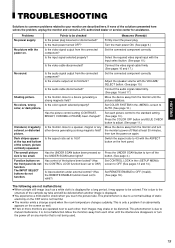
... been changed? Switch the aspect ratio to 16:9? No sound. Function buttons on the front panel. Is the main power turned OFF? Is the input signal selected properly? Is the aspect ratio set to AUTO. (See page 12.) Set each other device generating a strong magnetic field? Set COLOR SYSTEM... to minimum? The overall picture size is not being used. 19 Has control of the solutions presented here solves the problem, unplug the monitor and consult a JVC-authorized dealer or service center for a long period, it is only a problem if an abnormality appears on the CRT and is displayed ...
... been changed? Switch the aspect ratio to 16:9? No sound. Function buttons on the front panel. Is the main power turned OFF? Is the input signal selected properly? Is the aspect ratio set to AUTO. (See page 12.) Set each other device generating a strong magnetic field? Set COLOR SYSTEM... to minimum? The overall picture size is not being used. 19 Has control of the solutions presented here solves the problem, unplug the monitor and consult a JVC-authorized dealer or service center for a long period, it is only a problem if an abnormality appears on the CRT and is displayed ...
Instruction Manual
Page 22
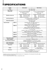
...mm (13-1/4") 418 mm (16-1/2") 25.6 kg (56.3 lbs) (not including input card) 19 kg (41.8 lbs) (not including input card) AC power cord POWER CORD HOLDER x 1 (case and cover) Screw x ... 15.734 kHz (NTSC), 15.625 kHz (PAL) V: 59.94 Hz (NTSC) 50 Hz (PAL) 750 TV lines or more (Y/C input mode) Composite video: 1 line, BNC connector x 2, 1 V(p-p), 75 Ω, negative sync (bridge connection ...Environmental conditions Power requirements Power consumption Dimensions Weight Accessory TM-H1950CG TM-H1750CG Color video monitor PAL, NTSC (3.58) 49 cm (19") measured diagonally, 90° deflection,...
...mm (13-1/4") 418 mm (16-1/2") 25.6 kg (56.3 lbs) (not including input card) 19 kg (41.8 lbs) (not including input card) AC power cord POWER CORD HOLDER x 1 (case and cover) Screw x ... 15.734 kHz (NTSC), 15.625 kHz (PAL) V: 59.94 Hz (NTSC) 50 Hz (PAL) 750 TV lines or more (Y/C input mode) Composite video: 1 line, BNC connector x 2, 1 V(p-p), 75 Ω, negative sync (bridge connection ...Environmental conditions Power requirements Power consumption Dimensions Weight Accessory TM-H1950CG TM-H1750CG Color video monitor PAL, NTSC (3.58) 49 cm (19") measured diagonally, 90° deflection,...

