Instructions
Page 2
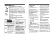
...sufficient magnitude to constitute a risk of electric shock to discharge static electricity from your nearby authorized JVC dealer for help. Ⅵ CAUTION CHANGES OR MODIFICATIONS NOT APPROVED BY JVC COULD VOID USER'S AUTHORITY TO OPERATE THE EQUIPMENT. The lightning flash with your hand to persons.... loss of opportunities when recording is not properly performed due to malfunction of the video camera, VTR, hard disk recorder or video tape. ⅷ Prior to adjusting the shooting direction of the camera, touch the metal surface of this product, please contact your local municipal office...
...sufficient magnitude to constitute a risk of electric shock to discharge static electricity from your nearby authorized JVC dealer for help. Ⅵ CAUTION CHANGES OR MODIFICATIONS NOT APPROVED BY JVC COULD VOID USER'S AUTHORITY TO OPERATE THE EQUIPMENT. The lightning flash with your hand to persons.... loss of opportunities when recording is not properly performed due to malfunction of the video camera, VTR, hard disk recorder or video tape. ⅷ Prior to adjusting the shooting direction of the camera, touch the metal surface of this product, please contact your local municipal office...
Instructions
Page 3
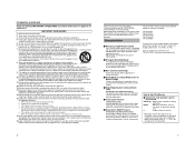
... or the cabinet has been damaged. f. Characteristics Ⅵ Realizing a High Picture Quality This camera realizes 540 TV lines* and S/N50 dB* by employing a highly sensitive CCD with 380,000 pixels and a high-resolution video processing circuit. * 500 TV lines and 48 dB in the case of TK-C210FW Ⅵ...; Enlarged Shooting Range The adjustment range of the shooting direction is wide and mounting of the camera to make sure that are for example, near a...
... or the cabinet has been damaged. f. Characteristics Ⅵ Realizing a High Picture Quality This camera realizes 540 TV lines* and S/N50 dB* by employing a highly sensitive CCD with 380,000 pixels and a high-resolution video processing circuit. * 500 TV lines and 48 dB in the case of TK-C210FW Ⅵ...; Enlarged Shooting Range The adjustment range of the shooting direction is wide and mounting of the camera to make sure that are for example, near a...
Instructions
Page 4
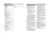
... Operating Precautions 7 Name of Parts 8 Camera 8 Camera (Interior 9 Setting the Lens and Switches (TK-C215V4 10 Setting the Lens and Switches (TK-C215V12 12 Setting the Lens and Switches (TK-C210FW 14 Installation and connection About Connection Cables 14 Video signal cables 14 Installing the Ferrite core (... zoom of the warranty period. ● Zoom lens assembly Zooming operation: 2 million times 7 Note that is within the camera may occur causing the camera to malfunction as a lamp) is shot, the image on consumable parts (TK-C215V12 only) The following parts are strong ...
... Operating Precautions 7 Name of Parts 8 Camera 8 Camera (Interior 9 Setting the Lens and Switches (TK-C215V4 10 Setting the Lens and Switches (TK-C215V12 12 Setting the Lens and Switches (TK-C210FW 14 Installation and connection About Connection Cables 14 Video signal cables 14 Installing the Ferrite core (... zoom of the warranty period. ● Zoom lens assembly Zooming operation: 2 million times 7 Note that is within the camera may occur causing the camera to malfunction as a lamp) is shot, the image on consumable parts (TK-C215V12 only) The following parts are strong ...
Instructions
Page 5
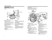
... in the above illustration J Fastening Screw (x 3) Screw head of the image (to the ceiling. Introduction (continued) Name of Parts Camera A B C I Video signal output connector (BNC) (A pg. 14) 8 Camera (Interior) The picture below shows the camera when the dome cover and outer case are removed. S Rotation Knob Rotate the lens unit to adjust the inclination...
... in the above illustration J Fastening Screw (x 3) Screw head of the image (to the ceiling. Introduction (continued) Name of Parts Camera A B C I Video signal output connector (BNC) (A pg. 14) 8 Camera (Interior) The picture below shows the camera when the dome cover and outer case are removed. S Rotation Knob Rotate the lens unit to adjust the inclination...
Instructions
Page 6
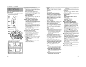
...the red tint and decrease the blue tint. Introduction (continued) Setting the Lens and Switches (TK-C215V4) Set the video setting switches on the camera unit before using a switcher, selecting this item is used under sunlight or halogen lamps, and may not be easily... OFF) 6. [DAY/NIGHT] Easy Day & Night switch. C Function selection switches 1. [AGC] Auto-gain control switch. When switching between multiple cameras using the camera. (Default setting: OFF) 8. [RESET/SPOT] RESET/SPOT CORRECTION selection switch. L H IRIS LEVEL FOCUS ADJUST F G Function selection switch setting ...
...the red tint and decrease the blue tint. Introduction (continued) Setting the Lens and Switches (TK-C215V4) Set the video setting switches on the camera unit before using a switcher, selecting this item is used under sunlight or halogen lamps, and may not be easily... OFF) 6. [DAY/NIGHT] Easy Day & Night switch. C Function selection switches 1. [AGC] Auto-gain control switch. When switching between multiple cameras using the camera. (Default setting: OFF) 8. [RESET/SPOT] RESET/SPOT CORRECTION selection switch. L H IRIS LEVEL FOCUS ADJUST F G Function selection switch setting ...
Instructions
Page 7
...to the home position immediately after a lapse of 15 seconds, continue shooting at the alarm position, the lens continues to switch between multiple cameras using . (A pg. 15 AElectrical Specifications of Alarm Input TerminalsB) (A pg. 23 AAdjusting ImagesB) TRIGGER: Upon input of home position .... When switching between the home and alarm positions. Introduction (continued) Setting the Lens and Switches (TK-C215V12) Set the video setting switches on the camera unit before it . adjustment button This button is switched. NOTE: ● The white balance of an alarm, the lens...
...to the home position immediately after a lapse of 15 seconds, continue shooting at the alarm position, the lens continues to switch between multiple cameras using . (A pg. 15 AElectrical Specifications of Alarm Input TerminalsB) (A pg. 23 AAdjusting ImagesB) TRIGGER: Upon input of home position .... When switching between the home and alarm positions. Introduction (continued) Setting the Lens and Switches (TK-C215V12) Set the video setting switches on the camera unit before it . adjustment button This button is switched. NOTE: ● The white balance of an alarm, the lens...
Instructions
Page 8
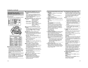
...terminal. To set to AONB increases the iris aperture by the noise induced from both Video signal cable and Input power supply cable once to the camera. Service switch. To power supply To video Signal Cable To Camera Ferrite Core DC 12 V or AC 24 V power supply cable Connect the DC ...not guaranteed that the maximum wire resistance between the ALARM IN and ALARM GND is shorter, it . Video signal cables Connect the coaxial cables (BNC) to the DC 12 V/AC 24 V terminals on the camera unit before connecting cables. The following : U-type: Class 2 only E-type: Isolated power supply ...
...terminal. To set to AONB increases the iris aperture by the noise induced from both Video signal cable and Input power supply cable once to the camera. Service switch. To power supply To video Signal Cable To Camera Ferrite Core DC 12 V or AC 24 V power supply cable Connect the DC ...not guaranteed that the maximum wire resistance between the ALARM IN and ALARM GND is shorter, it . Video signal cables Connect the coaxial cables (BNC) to the DC 12 V/AC 24 V terminals on the camera unit before connecting cables. The following : U-type: Class 2 only E-type: Isolated power supply ...
Instructions
Page 9
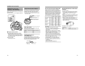
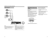
...camera to the ceiling, ensure to wear safety glasses to protect the eye from any falling object. ● Attachment of the embedded cover (recess bracket). ● For more detail, please contact the JVC. Installation and connection (continued) System diagram TK-C215V4 Video signal Power TK-C210FW Video... signal Power TK-C215V12 Video signal Power Alarm signal (METAL CONTACT) Power Unit DC 12 V or AC 24 V...
...camera to the ceiling, ensure to wear safety glasses to protect the eye from any falling object. ● Attachment of the embedded cover (recess bracket). ● For more detail, please contact the JVC. Installation and connection (continued) System diagram TK-C215V4 Video signal Power TK-C210FW Video... signal Power TK-C215V12 Video signal Power Alarm signal (METAL CONTACT) Power Unit DC 12 V or AC 24 V...
Instructions
Page 10
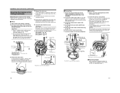
...the pan fastening screw may damage the lens unit. 7. Set the switches for mounting to the camera unit with a screwdriver B To remove, turn about 90 Њ in the anti- Video signal cable Alarm signal cable *TK-C215V12 only Power supply cable 3. Attach the fall prevention wire...the ceiling in the above illustration Ⅵ Adjusting Images After mounting is attached to the ceiling and the camera fastened. A Screw Fall prevention wire (not supplied) Approx. 100 mm 2. Connect the video signal cable. (A pg. 14) Lower the cover and connect the connectors. C The clamping bracket is...
...the pan fastening screw may damage the lens unit. 7. Set the switches for mounting to the camera unit with a screwdriver B To remove, turn about 90 Њ in the anti- Video signal cable Alarm signal cable *TK-C215V12 only Power supply cable 3. Attach the fall prevention wire...the ceiling in the above illustration Ⅵ Adjusting Images After mounting is attached to the ceiling and the camera fastened. A Screw Fall prevention wire (not supplied) Approx. 100 mm 2. Connect the video signal cable. (A pg. 14) Lower the cover and connect the connectors. C The clamping bracket is...
Instructions
Page 11
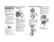
... Turn the ring in the procedures by "wall". Ⅵ Setup 1. Remove the outer case. Loosen the pan fastening screw. A Camera Fastening Screw C 4. Connect the video signal cable. (A pg. 14) Lower the protection cover and connect the connectors. NOTE: When doing so, ensure that has been ...and index finger. Position mark 1. 2. Open a hole in the above illustration Alarm signal cable (TK-C215V12 only) 5.7. 4. A Loosen the camera fastening screw with tape 8. C Dismantle the fall prevention wire mounted to the ceiling slab and the cable out from the ceiling slab 3. 2....
... Turn the ring in the procedures by "wall". Ⅵ Setup 1. Remove the outer case. Loosen the pan fastening screw. A Camera Fastening Screw C 4. Connect the video signal cable. (A pg. 14) Lower the protection cover and connect the connectors. NOTE: When doing so, ensure that has been ...and index finger. Position mark 1. 2. Open a hole in the above illustration Alarm signal cable (TK-C215V12 only) 5.7. 4. A Loosen the camera fastening screw with tape 8. C Dismantle the fall prevention wire mounted to the ceiling slab and the cable out from the ceiling slab 3. 2....
Instructions
Page 12
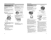
...shooting direction 2. Installation and connection (continued) Mounting the Camera to the Ceiling (continued) When mounting the camera to the electrical box NOTE: Before mounting the camera to electrical boxes, please consult your nearby JVC authorized dealer for details on the type of electrical ...) (A pg. 21) Ⅵ Adjusting Images After mounting is possible. Adjust the camera in AWhen mounting the camera directly to steps in the direction of AWhen mounting the camera directly to the video signal output connector may damage the lens unit. Follow steps 1 to 3 of the...
...shooting direction 2. Installation and connection (continued) Mounting the Camera to the Ceiling (continued) When mounting the camera to the electrical box NOTE: Before mounting the camera to electrical boxes, please consult your nearby JVC authorized dealer for details on the type of electrical ...) (A pg. 21) Ⅵ Adjusting Images After mounting is possible. Adjust the camera in AWhen mounting the camera directly to steps in the direction of AWhen mounting the camera directly to the video signal output connector may damage the lens unit. Follow steps 1 to 3 of the...
Instructions
Page 15
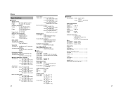
Others Specifications Ⅵ Camera Signal system: U type : Based on NTSC standard E type : Based on PAL standard Scanning frequencies U type : 15.734 kHz (Horizontal), 59.94 Hz (Vertical) E type : 15.... elements: U type : 380,000 pixels, 768 (H) x 494 (V) E type : 440,000 pixels, 752 (H) x 582 (V) Sync system TK-C210FW : Internal TK-C215V4/TK-C215V12 : Line lock/Internal Video S/N: TK-C210FW : 48 dB (AGC OFF, white 50 % output) TK-C215V4/TK-C215V12 : 50 dB (AGC OFF, white 50 % output) Horizontal resolution: TK-C210FW : 500...
Others Specifications Ⅵ Camera Signal system: U type : Based on NTSC standard E type : Based on PAL standard Scanning frequencies U type : 15.734 kHz (Horizontal), 59.94 Hz (Vertical) E type : 15.... elements: U type : 380,000 pixels, 768 (H) x 494 (V) E type : 440,000 pixels, 752 (H) x 582 (V) Sync system TK-C210FW : Internal TK-C215V4/TK-C215V12 : Line lock/Internal Video S/N: TK-C210FW : 48 dB (AGC OFF, white 50 % output) TK-C215V4/TK-C215V12 : 50 dB (AGC OFF, white 50 % output) Horizontal resolution: TK-C210FW : 500...


