Instruction Manual
Page 1
Retain this information for future reference. Model No. which is located on the body. FIXED DOME CAMERA TK-C2201U TK-C2201E INSTRUCTIONS For Customer Use: Enter below the Serial No. TK-C2201U,TK-C2201E Serial No. . LST0952-001A
Retain this information for future reference. Model No. which is located on the body. FIXED DOME CAMERA TK-C2201U TK-C2201E INSTRUCTIONS For Customer Use: Enter below the Serial No. TK-C2201U,TK-C2201E Serial No. . LST0952-001A
Instruction Manual
Page 2
Introduction Contents Introduction Contents ...2 Features ...3 Operating Precautions 4 Name of Parts ...6 Setup Setting the Switches 9 About Connection Cables 10 Installation Mounting the Camera 12 Adjustment Adjusting Image 17 Adjusting the Auto White Balance 22 Mounting the Dome Cover 23 Others Specifications 25 2
Introduction Contents Introduction Contents ...2 Features ...3 Operating Precautions 4 Name of Parts ...6 Setup Setting the Switches 9 About Connection Cables 10 Installation Mounting the Camera 12 Adjustment Adjusting Image 17 Adjusting the Auto White Balance 22 Mounting the Dome Cover 23 Others Specifications 25 2
Instruction Manual
Page 3
... notice. 3 Symbols such as , , ET and are subject to this manual. R v Design, specifications and other companies described in this manual. Before use of this manual v JVC holds the copyright to change for TK-C2201U/TK-C2201E.
... notice. 3 Symbols such as , , ET and are subject to this manual. R v Design, specifications and other companies described in this manual. Before use of this manual v JVC holds the copyright to change for TK-C2201U/TK-C2201E.

Instruction Manual
Page 4
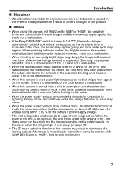
...at which corrosive gases are involved with a dry cloth. v Using this unit in the vicinity of the transmitting antenna of a radio or TV, devices that emit strong electromagnetic waves such as a transformer or motor, or wireless devices such as a transistor or mobile phone may give ... v This camera has been designed for indoor use. In a place with excessive dirt. v Do not install in a kitchen. - Maintenance m v Clean the dome cover lens using a lens wiper cloth (or a tissue). v Do not install the camera in use benzene or thinner to wipe the camera. m Energy Conservation ...
...at which corrosive gases are involved with a dry cloth. v Using this unit in the vicinity of the transmitting antenna of a radio or TV, devices that emit strong electromagnetic waves such as a transformer or motor, or wireless devices such as a transistor or mobile phone may give ... v This camera has been designed for indoor use. In a place with excessive dirt. v Do not install in a kitchen. - Maintenance m v Clean the dome cover lens using a lens wiper cloth (or a tissue). v Do not install the camera in use benzene or thinner to wipe the camera. m Energy Conservation ...
Instruction Manual
Page 5
... support wide range set to "ATW-N" or "ATW-W" and depending on the conditions of the object, the color tone may appear around 80 , the 57 dome cover can be visible into the image depending on the screen may have white vertical tailings (smear) or expansion (blooming) may differ slightly from a cold...
... support wide range set to "ATW-N" or "ATW-W" and depending on the conditions of the object, the color tone may appear around 80 , the 57 dome cover can be visible into the image depending on the screen may have white vertical tailings (smear) or expansion (blooming) may differ slightly from a cold...

Instruction Manual
Page 6
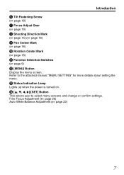
F ADJ M MENU N SET A Focus Adjustment Ring (A page 19) B Zoom Adjustment Ring (A page 19) C Fall Prevention Sheet (A page 13) D Rotation Knob (A page 18) E [MONITOR] Terminal (RCA pin) (A page 17) 6 .. Introduction Name of Parts Camera (Interior) The dome cover and inner dome are removed. Refer to "Mounting the camera directly to the ceiling or on the wall" (A page 13) step 2 to 3 on the removal methods. A G B H C I D J K E L F.
F ADJ M MENU N SET A Focus Adjustment Ring (A page 19) B Zoom Adjustment Ring (A page 19) C Fall Prevention Sheet (A page 13) D Rotation Knob (A page 18) E [MONITOR] Terminal (RCA pin) (A page 17) 6 .. Introduction Name of Parts Camera (Interior) The dome cover and inner dome are removed. Refer to "Mounting the camera directly to the ceiling or on the wall" (A page 13) step 2 to 3 on the removal methods. A G B H C I D J K E L F.
Instruction Manual
Page 7
M Status Indication Lamp Lights up when the power is turned on. Refer to select menu screens and change or confirm settings. Fine Focus Adjustment (A page 20) Auto White Balance Adjustment (A page 22) 7 N [J, K, H, I Pan Center Mark (A page 18) J Rotation Center Mark (A page 18) K Function Selection Switches (A page 9) L [MENU] Button Display the menu screen. Introduction F Tilt Fastening Screw (A page 18) G Focus Adjust Gear (A page 19) H Shooting Direction Mark (A page 15) (A page 18) I ]/[SET] Button This allows user to the attached manual "MENU SETTING" for more details about ...
M Status Indication Lamp Lights up when the power is turned on. Refer to select menu screens and change or confirm settings. Fine Focus Adjustment (A page 20) Auto White Balance Adjustment (A page 22) 7 N [J, K, H, I Pan Center Mark (A page 18) J Rotation Center Mark (A page 18) K Function Selection Switches (A page 9) L [MENU] Button Display the menu screen. Introduction F Tilt Fastening Screw (A page 18) G Focus Adjust Gear (A page 19) H Shooting Direction Mark (A page 15) (A page 18) I ]/[SET] Button This allows user to the attached manual "MENU SETTING" for more details about ...

Instruction Manual
Page 8
Introduction Name of Parts (Continued) Camera A B C A Mounting Hole 2 2 (A page 15) B Dome Cover (A page 13) C Inner Dome (A page 13) D Video Signal Output Connector (BNC) (A page 14) E Protection Cover (A page 14) F Power Supply Cable (A page 11) G Wiring Hole (A page 16) H Fall Prevention Wire Mounting Screw (A page 14) 8 D E F G H ..
Introduction Name of Parts (Continued) Camera A B C A Mounting Hole 2 2 (A page 15) B Dome Cover (A page 13) C Inner Dome (A page 13) D Video Signal Output Connector (BNC) (A page 14) E Protection Cover (A page 14) F Power Supply Cable (A page 11) G Wiring Hole (A page 16) H Fall Prevention Wire Mounting Screw (A page 14) 8 D E F G H ..
Instruction Manual
Page 9
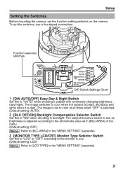
To set the function setting switches on the camera. The image is set in [BLC AREA] of the menu. (Default setting: OFF) Memo Refer to [BLC AREA] in the "MENU SETTING" (separate). 3 [MONITOR TYPE LCD/CRT] Monitor Type Selector Switch Set this to "ON" when shooting in the "MENU SETTING" (separate). 9 Setup Setting the Switches Before mounting the camera, set the switches, use . (Default setting: LCD) Memo Refer to see as brightness is dark. The image switches to color when the subject is bright, and black and white when it is adjusted according to the photometry area set to ...
To set the function setting switches on the camera. The image is set in [BLC AREA] of the menu. (Default setting: OFF) Memo Refer to [BLC AREA] in the "MENU SETTING" (separate). 3 [MONITOR TYPE LCD/CRT] Monitor Type Selector Switch Set this to "ON" when shooting in the "MENU SETTING" (separate). 9 Setup Setting the Switches Before mounting the camera, set the switches, use . (Default setting: LCD) Memo Refer to see as brightness is dark. The image switches to color when the subject is bright, and black and white when it is adjusted according to the photometry area set to ...
Instruction Manual
Page 10
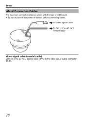
.. v Be sure to the video signal output connecter (BNC). 10 To video Signal Cable To DC 12 V or AC 24 V Power Supply Video signal cable (coaxial cable) Connect a RG-59 75 K coaxial cable (BNC) to turn off the power of cable used. Setup About Connection Cables The maximum connection distance varies with the type of devices before connecting cables.
.. v Be sure to the video signal output connecter (BNC). 10 To video Signal Cable To DC 12 V or AC 24 V Power Supply Video signal cable (coaxial cable) Connect a RG-59 75 K coaxial cable (BNC) to turn off the power of cable used. Setup About Connection Cables The maximum connection distance varies with the type of devices before connecting cables.
Instruction Manual
Page 11
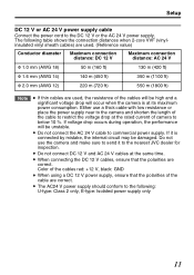
... and shorten the length of the cable are correct. v When connecting the DC 12 V cables, ensure that the polarities of the cable to the nearest JVC dealer for inspection. Color of camera to the DC 12 V or the AC 24 V power supply. Setup DC 12 V or AC 24 V power supply cable...
... and shorten the length of the cable are correct. v When connecting the DC 12 V cables, ensure that the polarities of the cable to the nearest JVC dealer for inspection. Color of camera to the DC 12 V or the AC 24 V power supply. Setup DC 12 V or AC 24 V power supply cable...
Instruction Manual
Page 12
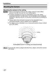
...in certain areas. v For details on its installation. Ceiling Embedded Cover in use for details on the embedded cover (recessed bracket), please contact your JVC dealer. v It maybe mandatory to protect the eye from any falling objects. v Please refer to the instruction manual for the embedded cover (recessed ...bracket) in Ceiling (recessed bracket) Memo To mount the camera using an electrical box, please contact the nearest JVC dealer. 12 .. If an embedded cover (recessed bracket) is required, ensure it is securely mounted before installing the camera.
...in certain areas. v For details on its installation. Ceiling Embedded Cover in use for details on the embedded cover (recessed bracket), please contact your JVC dealer. v It maybe mandatory to protect the eye from any falling objects. v Please refer to the instruction manual for the embedded cover (recessed ...bracket) in Ceiling (recessed bracket) Memo To mount the camera using an electrical box, please contact the nearest JVC dealer. 12 .. If an embedded cover (recessed bracket) is required, ensure it is securely mounted before installing the camera.
Instruction Manual
Page 13
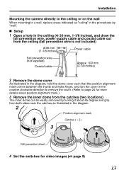
... (1-1/8 inches) Power cable Fall prevention wire (not supplied) Coaxial cable Approx. 100 mm (3-7/8 inches) 2 Remove the dome cover As illustrated in the diagram, hold the dome cover such that the position alignment mark comes between the thumb and index finger, and turn the cover in the counter...mark Catches ( 2) 3 Fall prevention sheet 4 Set the switches for more details about position alignment mark.) 3 Remove the inner dome from the catches (two locations) The inner dome can be easily removed by turning it about 45 degree and grip from both sides near the catches as illustrated in the...
... (1-1/8 inches) Power cable Fall prevention wire (not supplied) Coaxial cable Approx. 100 mm (3-7/8 inches) 2 Remove the dome cover As illustrated in the diagram, hold the dome cover such that the position alignment mark comes between the thumb and index finger, and turn the cover in the counter...mark Catches ( 2) 3 Fall prevention sheet 4 Set the switches for more details about position alignment mark.) 3 Remove the inner dome from the catches (two locations) The inner dome can be easily removed by turning it about 45 degree and grip from both sides near the catches as illustrated in the...

Instruction Manual
Page 14
Installation Mounting the Camera (Continued) Connection m 1 Attach the fall prevention wire is not included) 2 Connect the coaxial cable (A page 10) Lower the protection cover and connect the connectors. Upon connecting, restore the protection cover to the camera (fall prevention wire from the ceiling structures. 3 Connect the power supply cable (A page 11) 4 Wrap insulation tapes around the connecting parts of the power supply cables Memo Wrapping insulation tapes will isolate and protect the metallic parts of the connectors from the ceiling to cover the connectors. This will ...
Installation Mounting the Camera (Continued) Connection m 1 Attach the fall prevention wire is not included) 2 Connect the coaxial cable (A page 10) Lower the protection cover and connect the connectors. Upon connecting, restore the protection cover to the camera (fall prevention wire from the ceiling structures. 3 Connect the power supply cable (A page 11) 4 Wrap insulation tapes around the connecting parts of the power supply cables Memo Wrapping insulation tapes will isolate and protect the metallic parts of the connectors from the ceiling to cover the connectors. This will ...

Instruction Manual
Page 15
Tighten using an impact screwdriver, do so may damage the outer case. m Adjusting images After mounting is Φ 4.5 mm (3/16 inch). Installation m Mounting 1 Align (ñ) with the shooting direction, and mount the camera onto the ceiling Note Mounting screw (not included) v The diameter of the attachment hole is completed, adjust the images while checking the actual image. Failure to do not tighten the screws fully. v Do not use flathead screws. "Adjusting Image" (A page 17) 15 .. v When using your hand instead.
Tighten using an impact screwdriver, do so may damage the outer case. m Adjusting images After mounting is Φ 4.5 mm (3/16 inch). Installation m Mounting 1 Align (ñ) with the shooting direction, and mount the camera onto the ceiling Note Mounting screw (not included) v The diameter of the attachment hole is completed, adjust the images while checking the actual image. Failure to do not tighten the screws fully. v Do not use flathead screws. "Adjusting Image" (A page 17) 15 .. v When using your hand instead.

Instruction Manual
Page 16
Installation Mounting the Camera (Continued) Mount by allowing the cable to exit from the side When mounting the camera to the ceiling or a wall, it is identical to steps in "Mounting the camera directly to the ceiling or on the wall" (A page 13) . 1 Cut both ends of the extraction hole for the cable with a nipper and break off the excess material using tools such as long-nose pliers 2 Pull out the cable from the extraction hole and mount it to guide the cable from the side without opening any holes. .. . . The basic mounting method is possible to the ceiling or wall Cable 16
Installation Mounting the Camera (Continued) Mount by allowing the cable to exit from the side When mounting the camera to the ceiling or a wall, it is identical to steps in "Mounting the camera directly to the ceiling or on the wall" (A page 13) . 1 Cut both ends of the extraction hole for the cable with a nipper and break off the excess material using tools such as long-nose pliers 2 Pull out the cable from the extraction hole and mount it to guide the cable from the side without opening any holes. .. . . The basic mounting method is possible to the ceiling or wall Cable 16

Instruction Manual
Page 17
Discharge the static electricity from your body by touching the metallic part of the monitor terminal before handling the camera as static electricity may cause the camera to malfunction. 1 Mount the monitor Connect the monitor terminal of this camera to a test monitor to adjust the camera's shooting direction, image and focus. 2 Turn on the camera Monitor terminal 75 terminal Monitor 17 Adjustment Adjusting Image After mounting the camera, adjust the images while looking at the actual image. ..
Discharge the static electricity from your body by touching the metallic part of the monitor terminal before handling the camera as static electricity may cause the camera to malfunction. 1 Mount the monitor Connect the monitor terminal of this camera to a test monitor to adjust the camera's shooting direction, image and focus. 2 Turn on the camera Monitor terminal 75 terminal Monitor 17 Adjustment Adjusting Image After mounting the camera, adjust the images while looking at the actual image. ..

Instruction Manual
Page 18
Memo v Rotate both pan 175 and rotation 100 from the positions 57 57 aligned with the camera's shooting direction mark, pan center mark and rotation center mark. v As this camera has a wide tilt/rotation range, a part of this camera. Applying force on the field angle and direction. Adjustment Adjusting Image (Continued) 3 Adjust the shooting direction of this camera may appear on the screen depending on the lens unit may damage it. 18 v After adjusting the field angle, tighten and secure the tilt fastening screw so that the field angle will not be misaligned. Note v Moving ...
Memo v Rotate both pan 175 and rotation 100 from the positions 57 57 aligned with the camera's shooting direction mark, pan center mark and rotation center mark. v As this camera has a wide tilt/rotation range, a part of this camera. Applying force on the field angle and direction. Adjustment Adjusting Image (Continued) 3 Adjust the shooting direction of this camera may appear on the screen depending on the lens unit may damage it. 18 v After adjusting the field angle, tighten and secure the tilt fastening screw so that the field angle will not be misaligned. Note v Moving ...

Instruction Manual
Page 19
Knob Catch B A Focus adjustment ring Zoom adjustment ring Focus adjust gear C 19 After adjustment is opened too far out from B, remove the gear shaft from point A to point B as illustrated in diagram). Note To prevent the gear shaft from breaking when the gear is complete, fasten the screw with pressing it to the original position before using. ② Loosen the fastening screw for the zoom adjustment ring and move the ring to the left /right to adjust the image size. Adjustment 4 Adjust the image size Loosen the fastening screw for the focus adjustment ring and move...
Knob Catch B A Focus adjustment ring Zoom adjustment ring Focus adjust gear C 19 After adjustment is opened too far out from B, remove the gear shaft from point A to point B as illustrated in diagram). Note To prevent the gear shaft from breaking when the gear is complete, fasten the screw with pressing it to the original position before using. ② Loosen the fastening screw for the zoom adjustment ring and move the ring to the left /right to adjust the image size. Adjustment 4 Adjust the image size Loosen the fastening screw for the focus adjustment ring and move...
Instruction Manual
Page 20
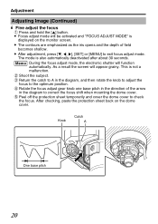
... the iris opens and the depth of the arrow in the diagram to correct the focus shift when mounting the dome cover. ⑤ Peel off the protection sheet temporarily and cover the dome cover to exit focus adjust mode. The mode is not a malfunction. ② Shoot the subject. ③ Return the catch.... After checking, paste the protection sheet back on the monitor screen. v Focus adjust mode will be activated and "FOCUS ADJUST MODE" is displayed on the dome cover. .. Knob Catch A One base pitch 20
... the iris opens and the depth of the arrow in the diagram to correct the focus shift when mounting the dome cover. ⑤ Peel off the protection sheet temporarily and cover the dome cover to exit focus adjust mode. The mode is not a malfunction. ② Shoot the subject. ③ Return the catch.... After checking, paste the protection sheet back on the monitor screen. v Focus adjust mode will be activated and "FOCUS ADJUST MODE" is displayed on the dome cover. .. Knob Catch A One base pitch 20