Instructions
Page 1
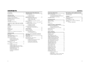
... CONNECTORS PREPARATIONS PREPARATIONS FOR OPERATION SETTING AND ADJUSTMENTS BEFORE SHOOTING SHOOTING OPERATION PLAYBACK MODE USING EXTERNAL COMPONENTS MENU SCREENS FEATURES OF THE CAMERA SECTION OTHERS LST0392- For Customer Use : Enter below the Serial No. LST0392- Before operating this JVC product. Retain this information for purchasing this unit, please read the instructions carefully to...
... CONNECTORS PREPARATIONS PREPARATIONS FOR OPERATION SETTING AND ADJUSTMENTS BEFORE SHOOTING SHOOTING OPERATION PLAYBACK MODE USING EXTERNAL COMPONENTS MENU SCREENS FEATURES OF THE CAMERA SECTION OTHERS LST0392- For Customer Use : Enter below the Serial No. LST0392- Before operating this JVC product. Retain this information for purchasing this unit, please read the instructions carefully to...

Instructions
Page 2
... into the apparatus, the apparatus has been exposed to rain or moisture, does not operate normally, or has been dropped. Servicing is used, use attachments/accessories specified by the manufacturer, or sold with the manufacturer's instructions. 8. Do not install near water. 6. A polarized plug... cart/apparatus combination to qualified service personnel. When a cart is required when the apparatus has been damaged in accordance with the apparatus. Use only with the cart, stand, tripod, bracket, or table specified by the manufacturer. 12. ing amplifiers) that produce heat. 9....
... into the apparatus, the apparatus has been exposed to rain or moisture, does not operate normally, or has been dropped. Servicing is used, use attachments/accessories specified by the manufacturer, or sold with the manufacturer's instructions. 8. Do not install near water. 6. A polarized plug... cart/apparatus combination to qualified service personnel. When a cart is required when the apparatus has been damaged in accordance with the apparatus. Use only with the cart, stand, tripod, bracket, or table specified by the manufacturer. 12. ing amplifiers) that produce heat. 9....
Instructions
Page 3
... the provisions and protection requirements of the apparatus is incorrectly replaced. II Important Safety Instructions FOR EUROPE This equipment is : JVC Technology Centre Europe GmbH P.O. e.g. Caution: Where there are subject to use any other power source. In such case, please keep the best performance and furthermore for example near a radio or TV...
... the provisions and protection requirements of the apparatus is incorrectly replaced. II Important Safety Instructions FOR EUROPE This equipment is : JVC Technology Centre Europe GmbH P.O. e.g. Caution: Where there are subject to use any other power source. In such case, please keep the best performance and furthermore for example near a radio or TV...
Instructions
Page 4
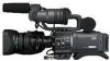
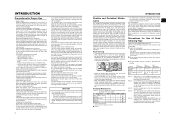
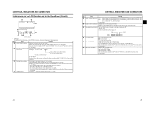
..., the FAS function automatically provides a wide range of compatibility with the same number of frames as ™, ® and © are not used . settes. A 2:3:3:2 pulldown (24p Advanced Mode) is not possible. You can select this manual. The speaker also outputs an alarm tone in ... effective scan lines, progressive scan) HDV 1080i (1080 effective scan lines, interlaced scan) This camcorder supports HDV 720p format. (HDV 720p, 480p, 576p) HDV and are for purchasing the JVC GY-HD110U/CHU, GYHD110E/CHE and GY-HD111E/CHE HD CAMERA RECORDER. The playback sound can be played ...
..., the FAS function automatically provides a wide range of compatibility with the same number of frames as ™, ® and © are not used . settes. A 2:3:3:2 pulldown (24p Advanced Mode) is not possible. You can select this manual. The speaker also outputs an alarm tone in ... effective scan lines, progressive scan) HDV 1080i (1080 effective scan lines, interlaced scan) This camcorder supports HDV 720p format. (HDV 720p, 480p, 576p) HDV and are for purchasing the JVC GY-HD110U/CHU, GYHD110E/CHE and GY-HD111E/CHE HD CAMERA RECORDER. The playback sound can be played ...
Instructions
Page 5
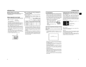
...Mode (Recording Check Function) HEADER REC Function 52 PLAYBACK MODE Playback Procedure 54 Fast-Forward, Rewind 54 Search 54 Outputting Audio 55 USING EXTERNAL COMPONENTS Connecting the Video Signal Cables 56 • Connecting the IEEE1394 Cable • Composite and Component Connections Dubbing with AV ... the menu settings to the factory settings • Initializing (formatting) an SD memory card FEATURES OF THE CAMERA SECTION How to Use Skin Detail 86 Outputting color bars 88 OTHERS Warnings and Responses 89 Troubleshooting 92 How to Display the Hour Meter 93 Information for ...
...Mode (Recording Check Function) HEADER REC Function 52 PLAYBACK MODE Playback Procedure 54 Fast-Forward, Rewind 54 Search 54 Outputting Audio 55 USING EXTERNAL COMPONENTS Connecting the Video Signal Cables 56 • Connecting the IEEE1394 Cable • Composite and Component Connections Dubbing with AV ... the menu settings to the factory settings • Initializing (formatting) an SD memory card FEATURES OF THE CAMERA SECTION How to Use Skin Detail 86 Outputting color bars 88 OTHERS Warnings and Responses 89 Troubleshooting 92 How to Display the Hour Meter 93 Information for ...
Instructions
Page 6
...; subject to reduce power consumption. • Cleaning the body: Wipe body with a head cleaning tape alone is left pointed at the most for use the camcorder continuously for 10 seconds at intervals half of the body, etc. To prevent wear and deterioration, clean the mechanical parts...and in the viewfinder during VTR playback in the below chart. Time management The accumulated running time). However, some of these spots are generated by JVC. X See "How to avoid operation hazards, do not leave the unit for periodical head cleaning. does not disappear after the tape has run...
...; subject to reduce power consumption. • Cleaning the body: Wipe body with a head cleaning tape alone is left pointed at the most for use the camcorder continuously for 10 seconds at intervals half of the body, etc. To prevent wear and deterioration, clean the mechanical parts...and in the viewfinder during VTR playback in the below chart. Time management The accumulated running time). However, some of these spots are generated by JVC. X See "How to avoid operation hazards, do not leave the unit for periodical head cleaning. does not disappear after the tape has run...
Instructions
Page 7
... occurs in the following batteries. • BN-V428, BN-V438 Videocassette to be Used • Use JVC's videocassette tapes marked with the A symbol. • Mini DV videocassette : M-DV63HD M-DV63PROHD * Do not use a dirty or damaged tape, as this unit. When this occurs, the head drum... videocassettes in a place with little humidity and good ventilation where mould does not form. • After a videocassette tape has been used upside down in a cold place and is characterized by dropouts, etc. As condensation forms gradually, the condensation indication may be cooled ...
... occurs in the following batteries. • BN-V428, BN-V438 Videocassette to be Used • Use JVC's videocassette tapes marked with the A symbol. • Mini DV videocassette : M-DV63HD M-DV63PROHD * Do not use a dirty or damaged tape, as this unit. When this occurs, the head drum... videocassettes in a place with little humidity and good ventilation where mould does not form. • After a videocassette tape has been used upside down in a cold place and is characterized by dropouts, etc. As condensation forms gradually, the condensation indication may be cooled ...
Instructions
Page 8
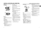
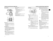
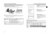
... 15 is set the Iris Mode switch 7 to select whether or not the lamp should light and the lighting pattern. The luminance level can be used for the microphone holder 3. 3Microphone holder Makes it is held down only. 9[S] IRIS speed adjusting control For adjusting the iris operation speed. X See "...ring clockwise until the object is focused. X See "Attaching the Zoom Lens" on page 45. 8Lens mounting ring/Lens lock lever Hold the lens and use this switch is set the focus ring 1 to the infinite position (f) and the zoom ring 2 to position "M". 3IRIS ring Manual iris ring. It ...
... 15 is set the Iris Mode switch 7 to select whether or not the lamp should light and the lighting pattern. The luminance level can be used for the microphone holder 3. 3Microphone holder Makes it is held down only. 9[S] IRIS speed adjusting control For adjusting the iris operation speed. X See "...ring clockwise until the object is focused. X See "Attaching the Zoom Lens" on page 45. 8Lens mounting ring/Lens lock lever Hold the lens and use this switch is set the focus ring 1 to the infinite position (f) and the zoom ring 2 to position "M". 3IRIS ring Manual iris ring. It ...
Instructions
Page 9
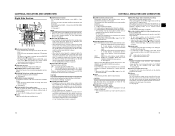
...code and user's bits is a stereo mini-jack for connecting an earphone for setting the time code generator to adjust the audio levels using a stereotype jack and stereo sound should be output, the following setting should light and the lighting pattern. When you press this position to.... * If this position to display the user's bits values. 4[TC GENE.] Time code generator setting switch Switch for audio monitoring. It is also used when recording scenes one after another , the time codes are recorded as continuous time codes. : Regeneration mode, in the CH-1/CH-2 AUDIO LEVEL area...
...code and user's bits is a stereo mini-jack for connecting an earphone for setting the time code generator to adjust the audio levels using a stereotype jack and stereo sound should be output, the following setting should light and the lighting pattern. When you press this position to.... * If this position to display the user's bits values. 4[TC GENE.] Time code generator setting switch Switch for audio monitoring. It is also used when recording scenes one after another , the time codes are recorded as continuous time codes. : Regeneration mode, in the CH-1/CH-2 AUDIO LEVEL area...
Instructions
Page 10
...constantly sampled for the 1394 REC TRIGGER item on the OTHERS [2/2] menu screen, this button becomes the start /stop recording) Start and stop recording using this button. (This works together with the SWITCH MODE menu screen. X See "Backup Recording" on the CAMERA OPERATION menu screen. DV : ... switch. c[WHT.BAL] White balance switch Three white balance modes are not using the USER1 - 3 items in the viewfinder or on the inner side of the camera. A : Switch into A. CAUTION There is a risk that the camcorder will be EE monitored. e[POWER] Power ON/OFF switch Switch that it ...
...constantly sampled for the 1394 REC TRIGGER item on the OTHERS [2/2] menu screen, this button becomes the start /stop recording) Start and stop recording using this button. (This works together with the SWITCH MODE menu screen. X See "Backup Recording" on the CAMERA OPERATION menu screen. DV : ... switch. c[WHT.BAL] White balance switch Three white balance modes are not using the USER1 - 3 items in the viewfinder or on the inner side of the camera. A : Switch into A. CAUTION There is a risk that the camcorder will be EE monitored. e[POWER] Power ON/OFF switch Switch that it ...
Instructions
Page 11
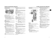
...result in the SET UP item. dBattery pack Attach the provided battery pack (BN-V428). X See "AC Operation" on the top section opens this camcorder. • You can insert and remove the SD memory card. HDV : For HDV format DV : DV format 4[IEEE1394] IEEE1394 connector (6-pin...to indicate STOP, playback operations become possible. MEMO You can also select whether or not to be connected. • Set the CH-2 audio input connector using them. 6Cassette cover Sliding the EJECT switch a on page 17 located on page 32. 2[LINE OUTPUT] Line output connector ()3.5mm) Output connector for ...
...result in the SET UP item. dBattery pack Attach the provided battery pack (BN-V428). X See "AC Operation" on the top section opens this camcorder. • You can insert and remove the SD memory card. HDV : For HDV format DV : DV format 4[IEEE1394] IEEE1394 connector (6-pin...to indicate STOP, playback operations become possible. MEMO You can also select whether or not to be connected. • Set the CH-2 audio input connector using them. 6Cassette cover Sliding the EJECT switch a on page 17 located on page 32. 2[LINE OUTPUT] Line output connector ()3.5mm) Output connector for ...
Instructions
Page 12
...8226; Pressing this button during playback, still picture playback or forward search initiates reverse search. BOTH : CH-1 and CH-2 channel audio are using an Anton-Bauer battery or IDX battery, the LCD monitor and viewfinder display switches each time the button is displayed on the LCD Monitor ...; CAMERA MODE (display example) STATUS 0 STATUS 1 „ Status screens (screens for about 10 seconds before the automatic adjustment of FAS is used to select whether the mixed sound or stereo sound should be output via the PHONES jack. (AUDIO MONITOR item on the AUDIO/MIC [2/2] menu ...
...8226; Pressing this button during playback, still picture playback or forward search initiates reverse search. BOTH : CH-1 and CH-2 channel audio are using an Anton-Bauer battery or IDX battery, the LCD monitor and viewfinder display switches each time the button is displayed on the LCD Monitor ...; CAMERA MODE (display example) STATUS 0 STATUS 1 „ Status screens (screens for about 10 seconds before the automatic adjustment of FAS is used to select whether the mixed sound or stereo sound should be output via the PHONES jack. (AUDIO MONITOR item on the AUDIO/MIC [2/2] menu ...
Instructions
Page 14
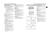
... X See page 72. 6 Audio level meter indication Displays the CH-1, CH-2 audio level meters. Whether or not to display this display ON/OFF using the FORMAT item on the LCD/VF [1/3] menu screen. item on the LCD/VF [2/3] menu screen. You can be shown is set with the ...Item Contents 1 VIDEO FORMAT display Displays the currently selected video format. X See page 75. * When inserting a brand-new tape, the remaining tape time is used at which audio is recorded on the LCD/VF [1/3] menu screen. Item Contents 5 Audio sampling frequency in- 32 K : Indicated when the AUDIO MODE item...
... X See page 72. 6 Audio level meter indication Displays the CH-1, CH-2 audio level meters. Whether or not to display this display ON/OFF using the FORMAT item on the LCD/VF [1/3] menu screen. item on the LCD/VF [2/3] menu screen. You can be shown is set with the ...Item Contents 1 VIDEO FORMAT display Displays the currently selected video format. X See page 75. * When inserting a brand-new tape, the remaining tape time is used at which audio is recorded on the LCD/VF [1/3] menu screen. Item Contents 5 Audio sampling frequency in- 32 K : Indicated when the AUDIO MODE item...

Instructions
Page 15
... status STBY, STOP, PLAY, REC, FF, REW, FWD, REV, STL, - - - (No tape loaded), SLOW: During variable play- A F symbol is saved using STORE FILE. The display disappears when the setting is displayed when a menu setting read from LOAD FILE was changed. X See page 75. 2 Time code (TC... and time should be displayed and the display style are being recorded (hour, minute, second, frame) when in reverse direction (Displayed when using the TC DISPLAY switch in the LCD door. 3 Remaining tape time Remaining tape indication (displayed in 1-minute steps) This indicator blinks when ...
... status STBY, STOP, PLAY, REC, FF, REW, FWD, REV, STL, - - - (No tape loaded), SLOW: During variable play- A F symbol is saved using STORE FILE. The display disappears when the setting is displayed when a menu setting read from LOAD FILE was changed. X See page 75. 2 Time code (TC... and time should be displayed and the display style are being recorded (hour, minute, second, frame) when in reverse direction (Displayed when using the TC DISPLAY switch in the LCD door. 3 Remaining tape time Remaining tape indication (displayed in 1-minute steps) This indicator blinks when ...
Instructions
Page 16
... SAFETY ZONE item and CENTER MARK item on the LCD/VF [1/3] menu screen. X See "Setting Menu Screens" on page 45. „ Menu Setting Screen Screen used for making various settings. If an alarm is generated while the STATUS 2, 3 screen is 1394 input in magnified size. 1 DISPLAY button LCD BRIGHT CAHU-1DIOSELECT...
... SAFETY ZONE item and CENTER MARK item on the LCD/VF [1/3] menu screen. X See "Setting Menu Screens" on page 45. „ Menu Setting Screen Screen used for making various settings. If an alarm is generated while the STATUS 2, 3 screen is 1394 input in magnified size. 1 DISPLAY button LCD BRIGHT CAHU-1DIOSELECT...

Instructions
Page 17
... details, please consult your JVC authorized dealer. 28 29 UB RFRECEE REGEN LCD open /close less than 40° When using these batteries and the LCD+VF item in the LCD/ VF [3/3] menu is set to OFF, the LCD monitor and viewfinder (VF) displays are as shown below . Use a FUJINON focus manual unit...cancelled by the LCD monitor open 40° or more LCD close and normal/inverted operations. • If the LCD monitor is closed inside the camcorder with the screen in the normal display orientation, holding down the DISPLAY button does not work. • You can set the LCD monitor and ...
... details, please consult your JVC authorized dealer. 28 29 UB RFRECEE REGEN LCD open /close less than 40° When using these batteries and the LCD+VF item in the LCD/ VF [3/3] menu is set to OFF, the LCD monitor and viewfinder (VF) displays are as shown below . Use a FUJINON focus manual unit...cancelled by the LCD monitor open 40° or more LCD close and normal/inverted operations. • If the LCD monitor is closed inside the camcorder with the screen in the normal display orientation, holding down the DISPLAY button does not work. • You can set the LCD monitor and ...
Instructions
Page 18
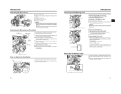
... the SD memory card straight out. „ About SD Memory Cards • When you use of the arrow. X See page 85. z Attach the core filter (black) as close to perform the correct setting for this camcorder. Tighten the mount ring. 4. Clamp the lens cable. CAUTION • Be sure to secure... pin aligned with the cassette cover. 3. Clamp Connect the provided microphone to the INPUT1 or INPUT2 input connector on a device other than this camcorder. Turn the knob on the side of the arrow. Connect the microphone cable to the microphone holder. Push the SD memory card in the ...
... the SD memory card straight out. „ About SD Memory Cards • When you use of the arrow. X See page 85. z Attach the core filter (black) as close to perform the correct setting for this camcorder. Tighten the mount ring. 4. Clamp the lens cable. CAUTION • Be sure to secure... pin aligned with the cassette cover. 3. Clamp Connect the provided microphone to the INPUT1 or INPUT2 input connector on a device other than this camcorder. Turn the knob on the side of the arrow. Connect the microphone cable to the microphone holder. Push the SD memory card in the ...
Instructions
Page 19
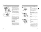
... takes places with a battery pack. • The power is cut off for about 3 months after the battery pack capacity has been used . 33 CAUTION • When using the provided AC Adapter. * Be sure to the GY-HD110, unplug the cable. 1. Connect the provided AC adapter to remove it is...Pack from a power supply. Leave the equipment in this condition for about 4 hours. • The built-in battery will be used up, set to charge 1. Use the supplied AC adapter as shown in , rechargeable backup battery retains the date and time and the time code data. Power is ...
... takes places with a battery pack. • The power is cut off for about 3 months after the battery pack capacity has been used . 33 CAUTION • When using the provided AC Adapter. * Be sure to the GY-HD110, unplug the cable. 1. Connect the provided AC adapter to remove it is...Pack from a power supply. Leave the equipment in this condition for about 4 hours. • The built-in battery will be used up, set to charge 1. Use the supplied AC adapter as shown in , rechargeable backup battery retains the date and time and the time code data. Power is ...
Instructions
Page 20
...immediately after a long storage period, charging time will be longer than indicated above. • When two battery packs are attached, they are used for charging. In this condition, press the REC/VTR trigger button to a high temperature (under direct sunlight in a car, etc.), ... Battery Operation (Cont'd) „ Remaining Battery Power Display LCD monitor/Viewfinder When the remaining battery power is nearly exhausted, the following statuses. Use the values in the Camera mode) • Alarm indication: LOW VOLTAGE displayed. „ FRONT and BACK TALLY lamp on camera: Blinks ...
...immediately after a long storage period, charging time will be longer than indicated above. • When two battery packs are attached, they are used for charging. In this condition, press the REC/VTR trigger button to a high temperature (under direct sunlight in a car, etc.), ... Battery Operation (Cont'd) „ Remaining Battery Power Display LCD monitor/Viewfinder When the remaining battery power is nearly exhausted, the following statuses. Use the values in the Camera mode) • Alarm indication: LOW VOLTAGE displayed. „ FRONT and BACK TALLY lamp on camera: Blinks ...
Instructions
Page 21
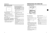
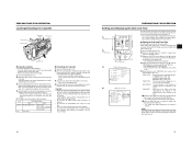
... switch REC SAVE Record-standby mode STOP mode REC INHIBIT is in clock (time compensation) and displays it becomes half-locked and the camcorder cannot function. Rotate the SHUTTER dial to align the cursor (K) with the TIME/DATE item, and then press the SHUTTER dial. •...screen to ON. 5. PREPARATIONS FOR OPERATION Loading/Unloading the Cassette EJECT switch Cassette holder REC/SAVE switch Tape window Cassette cover „ Cassette Loading Use a videocassette tape marked MiniDV. • To record, slide the switch on the back for 1 second or longer to dis- Turn the POWER ...
... switch REC SAVE Record-standby mode STOP mode REC INHIBIT is in clock (time compensation) and displays it becomes half-locked and the camcorder cannot function. Rotate the SHUTTER dial to align the cursor (K) with the TIME/DATE item, and then press the SHUTTER dial. •...screen to ON. 5. PREPARATIONS FOR OPERATION Loading/Unloading the Cassette EJECT switch Cassette holder REC/SAVE switch Tape window Cassette cover „ Cassette Loading Use a videocassette tape marked MiniDV. • To record, slide the switch on the back for 1 second or longer to dis- Turn the POWER ...


