Instructions
Page 4
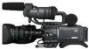
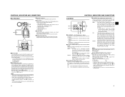
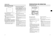
... connecting to HDV/DV devices. 3 Battery pack AC Adapter DC Cable Power Cord For GY-HD110U Power Cord For GY-HD110E/GY-HD111E Core Filters For DC Cable (Gray)/View- finder Cable (Black) Clamp Filters For Audio/IEEE1394 Cable Audio Cable SD memory card 2 MAIN FEATURES • This camcorder records in the DVCAM format is converted to 3 minutes from the video output connectors. tion) video on other units (including another GY-HD110) are set off by "(U model...
... connecting to HDV/DV devices. 3 Battery pack AC Adapter DC Cable Power Cord For GY-HD110U Power Cord For GY-HD110E/GY-HD111E Core Filters For DC Cable (Gray)/View- finder Cable (Black) Clamp Filters For Audio/IEEE1394 Cable Audio Cable SD memory card 2 MAIN FEATURES • This camcorder records in the DVCAM format is converted to 3 minutes from the video output connectors. tion) video on other units (including another GY-HD110) are set off by "(U model...
Instructions
Page 5
... Date on the Screen Displaying Time Code 39 Recording Time Codes in Continuation of Time Codes Recorded on Tape 40 Presetting and Recording of Time Code 40 • Presetting time code data • Presetting user's bit data Synchronizing with the Time Code of the IEEE1394 (DV)-Connected Master Unit 42 Screen Adjustment 43 Viewfinder Adjustment 43 Back Focus Adjustment 44 White Balance Adjustment 45 • White Balance Adjustment • Full Auto White Balance (FAW) SETTING AND ADJUSTMENTS BEFORE SHOOTING Setting the Video Format 46 Camera Settings 47 Screen Size (4:3/16:9) Mode...
... Date on the Screen Displaying Time Code 39 Recording Time Codes in Continuation of Time Codes Recorded on Tape 40 Presetting and Recording of Time Code 40 • Presetting time code data • Presetting user's bit data Synchronizing with the Time Code of the IEEE1394 (DV)-Connected Master Unit 42 Screen Adjustment 43 Viewfinder Adjustment 43 Back Focus Adjustment 44 White Balance Adjustment 45 • White Balance Adjustment • Full Auto White Balance (FAW) SETTING AND ADJUSTMENTS BEFORE SHOOTING Setting the Video Format 46 Camera Settings 47 Screen Size (4:3/16:9) Mode...
Instructions
Page 6
... for 1 to 2 times ev- 1 to 2 times ev- 1 to OFF or remove the power cable during playback, edit search, and recording check using the cleaning tape, please follow the instructions of professional video equipment at the most for each cleaning. „ Use the following chart as the indicator will promote the wear and deterioration of the image. indicator may be damaged. • The sensitivity level of Head Cleaning Tape" about how...
... for 1 to 2 times ev- 1 to 2 times ev- 1 to OFF or remove the power cable during playback, edit search, and recording check using the cleaning tape, please follow the instructions of professional video equipment at the most for each cleaning. „ Use the following chart as the indicator will promote the wear and deterioration of the image. indicator may be damaged. • The sensitivity level of Head Cleaning Tape" about how...
Instructions
Page 9
... adjusted with the ALARM VR LEVEL item on page 15. The audio output level is a stereo mini-jack for connecting an earphone for setting the time code generator to display time code values. AUTO MANUAL : The audio level is set with the Audio monitor volume control 3 on page 77. 5[CAM/VTR] Camera/VTR mode switch button Each time you press this button, the mode switches between scenes. : The preset mode is used when recording scenes one after another, the time codes are recorded as continuous time codes. : Regeneration mode...
... adjusted with the ALARM VR LEVEL item on page 15. The audio output level is a stereo mini-jack for connecting an earphone for setting the time code generator to display time code values. AUTO MANUAL : The audio level is set with the Audio monitor volume control 3 on page 77. 5[CAM/VTR] Camera/VTR mode switch button Each time you press this button, the mode switches between scenes. : The preset mode is used when recording scenes one after another, the time codes are recorded as continuous time codes. : Regeneration mode...
Instructions
Page 10
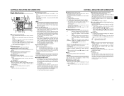
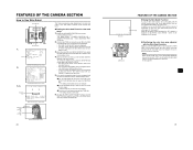
... on the direction toward the rear section. A : Switch into white balance mode memorized in ND filter. item on page 62. dStand When attaching the lens, slide the stand forward. HDV : Lights when the format is DV. MEMO • During a system error, HDV/DV flash alternately. iLCD door lock and release knob To open the LCD door, move this button while the menu screen is displayed in...
... on the direction toward the rear section. A : Switch into white balance mode memorized in ND filter. item on page 62. dStand When attaching the lens, slide the stand forward. HDV : Lights when the format is DV. MEMO • During a system error, HDV/DV flash alternately. iLCD door lock and release knob To open the LCD door, move this button while the menu screen is displayed in...
Instructions
Page 11
... the video signal output connector. X See "LCD/VF [1/3] Menu Screen" on page 74. 8[REC] REC trigger button (start/stop recording) Start and stop recording using them. 6Cassette cover Sliding the EJECT switch a on page 17 located on the VIDEO FORMAT menu. When an SD memory card is also displayed in progress. The LED lights while ejecting is connected. X See page 80. The reference input level is displayed in the Camera mode to set to indicate STOP, playback operations become possible. bShoulder pad 16 CONTROLS...
... the video signal output connector. X See "LCD/VF [1/3] Menu Screen" on page 74. 8[REC] REC trigger button (start/stop recording) Start and stop recording using them. 6Cassette cover Sliding the EJECT switch a on page 17 located on the VIDEO FORMAT menu. When an SD memory card is also displayed in progress. The LED lights while ejecting is connected. X See page 80. The reference input level is displayed in the Camera mode to set to indicate STOP, playback operations become possible. bShoulder pad 16 CONTROLS...

Instructions
Page 15
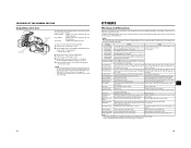
... from LOAD FILE was changed. CONTROLS, INDICATORS AND CONNECTORS „ Status Screen in VTR mode. (UB) display You can select to display either the time code or the user's bits using non-linear editing software.) (SLOW-1: About ×-0.1 speed, SLOW-2: About ×-0.2 speed, SLOW-3: About ×-0.5 speed) 8 Time/Date indication Recorded data are set , the following indication appears. 9 Voltage indication (Example) 7.0V : Indicates remaining battery level in 1-minute steps) This indicator blinks when remaining tape time is locked...
... from LOAD FILE was changed. CONTROLS, INDICATORS AND CONNECTORS „ Status Screen in VTR mode. (UB) display You can select to display either the time code or the user's bits using non-linear editing software.) (SLOW-1: About ×-0.1 speed, SLOW-2: About ×-0.2 speed, SLOW-3: About ×-0.5 speed) 8 Time/Date indication Recorded data are set , the following indication appears. 9 Voltage indication (Example) 7.0V : Indicates remaining battery level in 1-minute steps) This indicator blinks when remaining tape time is locked...
Instructions
Page 16
... battery or IDX battery, characters are displayed while the STATUS (0, 1, 4) screen is shown in magnified size on the LCD monitor. * When this unit is being operated with an error code is displayed. Only image displayed Characters shown enlarged Image and characters displayed No. Indicator FREE : TC GENE switch is set to ON. 3 Drop/Non-drop Indicator Displayed during the auto white balance adjustment operation. menu is set to PRESET-FREE RUN MODE. DF : During playback of DR-HD100 Oper...
... battery or IDX battery, characters are displayed while the STATUS (0, 1, 4) screen is shown in magnified size on the LCD monitor. * When this unit is being operated with an error code is displayed. Only image displayed Characters shown enlarged Image and characters displayed No. Indicator FREE : TC GENE switch is set to ON. 3 Drop/Non-drop Indicator Displayed during the auto white balance adjustment operation. menu is set to PRESET-FREE RUN MODE. DF : During playback of DR-HD100 Oper...
Instructions
Page 20
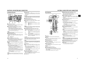
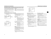
... POWER switch VF BRIGHT USER 1 USER 2 SHUTTER ND FILTER 2 1 MENU OFF USER 3 STATUS WHT.BAL AUTO AUTO AUDIO CH-1 LEVEL CH-2 ON OFF POWER REC LCD BRIGHT - + AUDIO SELECT CH-1 CH-2 AUTO MANU CAM/VTR TC ProHD DISPLAY GENE. Do not leave the battery pack in the viewfinder. Repeated recharging with Battery Pack When a fully charged battery pack is attached, the approximate continuous operating time is as follows Battery Pack Continuous Operating Time (at least 5 seconds before turning...
... POWER switch VF BRIGHT USER 1 USER 2 SHUTTER ND FILTER 2 1 MENU OFF USER 3 STATUS WHT.BAL AUTO AUTO AUDIO CH-1 LEVEL CH-2 ON OFF POWER REC LCD BRIGHT - + AUDIO SELECT CH-1 CH-2 AUTO MANU CAM/VTR TC ProHD DISPLAY GENE. Do not leave the battery pack in the viewfinder. Repeated recharging with Battery Pack When a fully charged battery pack is attached, the approximate continuous operating time is as follows Battery Pack Continuous Operating Time (at least 5 seconds before turning...
Instructions
Page 21
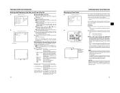
... LCD monitor and in the viewfinder. PREPARATIONS FOR OPERATION Loading/Unloading the Cassette EJECT switch Cassette holder REC/SAVE switch Tape window Cassette cover „ Cassette Loading Use a videocassette tape marked MiniDV. • To record, slide the switch on the back for use in preventing accidental erasure to the "REC" side. • Remove any the tape slack before the videocassette tape is ejected. 3. Press the STATUS button for a long time. play the TOP MENU screen. 3. MODE Camera VTR REC/SAVE switch REC SAVE Record-standby mode STOP mode...
... LCD monitor and in the viewfinder. PREPARATIONS FOR OPERATION Loading/Unloading the Cassette EJECT switch Cassette holder REC/SAVE switch Tape window Cassette cover „ Cassette Loading Use a videocassette tape marked MiniDV. • To record, slide the switch on the back for use in preventing accidental erasure to the "REC" side. • Remove any the tape slack before the videocassette tape is ejected. 3. Press the STATUS button for a long time. play the TOP MENU screen. 3. MODE Camera VTR REC/SAVE switch REC SAVE Record-standby mode STOP mode...
Instructions
Page 22
... user's bit data are displayed on the tape are displayed in HDV format. (GY- When all the settings are completed, rotate the SHUTTER dial to REGEN mode when recording DV input signal from the are displayed. Set the TIME/DATE menu screen. • DISPLAY item : Sets whether or not date and time should be set the TC DUPLI. CAM : Displayed when outputting the color camera image. DATE : Date only is rotated upward, the value becomes higher. In VTR stop mode displays the DV input time code data...
... user's bit data are displayed on the tape are displayed in HDV format. (GY- When all the settings are completed, rotate the SHUTTER dial to REGEN mode when recording DV input signal from the are displayed. Set the TIME/DATE menu screen. • DISPLAY item : Sets whether or not date and time should be set the TC DUPLI. CAM : Displayed when outputting the color camera image. DATE : Date only is rotated upward, the value becomes higher. In VTR stop mode displays the DV input time code data...
Instructions
Page 23
.../UB/CLOCK menu screen. To cancel the setting, select CANCEL and press the SHUTTER dial. 3. betic letters from the internal time code generator can zero reset the time code data by 10. REC FREE : The data preset in scene accuracy. DROP : The time code generator's running method is approximately 29.97 frames, but per time code 30 frames are identical to be recorded at the time of the blinking digit changes. Set the time code (hours...
.../UB/CLOCK menu screen. To cancel the setting, select CANCEL and press the SHUTTER dial. 3. betic letters from the internal time code generator can zero reset the time code data by 10. REC FREE : The data preset in scene accuracy. DROP : The time code generator's running method is approximately 29.97 frames, but per time code 30 frames are identical to be recorded at the time of the blinking digit changes. Set the time code (hours...
Instructions
Page 29
... FREE RUN mode) „ HEADER REC menu screen contents Item START KEY TC DATA UB DATA BARS TIME BLACK TIME PAGE BACK Function/Initial Setting Sets whether the HEADER REC operation should be executed when the REC/VTR trigger button is pressed while the STOP button is engaged following completion of the blinking digit changes. ZERO PRESET: Resets all time codes to set for the duration specified in signal generator at the start of the tape. DISABLE : HEADER REC operation...
... FREE RUN mode) „ HEADER REC menu screen contents Item START KEY TC DATA UB DATA BARS TIME BLACK TIME PAGE BACK Function/Initial Setting Sets whether the HEADER REC operation should be executed when the REC/VTR trigger button is pressed while the STOP button is engaged following completion of the blinking digit changes. ZERO PRESET: Resets all time codes to set for the duration specified in signal generator at the start of the tape. DISABLE : HEADER REC operation...
Instructions
Page 31
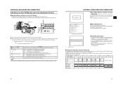
... connect the IEEE1394 cable under the condition of static electricity. • Turn the power of both devices on. 3. Composite cable or Component cable PB VIDEO/Y IEEE 1394 HDV DV LINE OUTPUT connector 1. AUDIO menu screen USING EXTERNAL COMPONENTS By connecting the video signal output terminal and the LINE OUTPUT terminal on the recording unit. Set the camcorder to automatically detect the video format of the playback tape or only play back only a particular format. Press the CAM/VTR button. Recording...
... connect the IEEE1394 cable under the condition of static electricity. • Turn the power of both devices on. 3. Composite cable or Component cable PB VIDEO/Y IEEE 1394 HDV DV LINE OUTPUT connector 1. AUDIO menu screen USING EXTERNAL COMPONENTS By connecting the video signal output terminal and the LINE OUTPUT terminal on the recording unit. Set the camcorder to automatically detect the video format of the playback tape or only play back only a particular format. Press the CAM/VTR button. Recording...

Instructions
Page 32
... Recording unit PB VIDEO/Y PR DC INPUT LINE OUTPUT IEEE1394 Signal flow 2. IEEE1394 cable CAUTION • Set the IEEE1394 switch on this unit when switching modes from STILL to either HDV or DV. • Start recording after making sure that both devices are low resolution images. Connect the IEEE1394 cable. 3. Turn both units. 4. Set the camcorder to automatically detect the playback tape video format or play back only a particular format. The VTR indicator lights. 5. Set...
... Recording unit PB VIDEO/Y PR DC INPUT LINE OUTPUT IEEE1394 Signal flow 2. IEEE1394 cable CAUTION • Set the IEEE1394 switch on this unit when switching modes from STILL to either HDV or DV. • Start recording after making sure that both devices are low resolution images. Connect the IEEE1394 cable. 3. Turn both units. 4. Set the camcorder to automatically detect the playback tape video format or play back only a particular format. The VTR indicator lights. 5. Set...
Instructions
Page 35
... mode (2:3:3:2 pulldown), 720/24p. DV : During tape playback, only the part of the cables connected to the FRAME RATE. Set the style to this item is switched automatically and played back. LETTER : Wide image with the sides cut is displayed. Initial settings: U model: 7.5% E model: 0.0% MEMO When the FRAME RATE item is set Connector (G: Unconnected F: Connected) VIDEO/Y PB PR F F F F G F F F G F G G None of 16:9. MENU SCREENS VIDEO FORMAT Menu Screen * This is not displayed in the vertical direction...
... mode (2:3:3:2 pulldown), 720/24p. DV : During tape playback, only the part of the cables connected to the FRAME RATE. Set the style to this item is switched automatically and played back. LETTER : Wide image with the sides cut is displayed. Initial settings: U model: 7.5% E model: 0.0% MEMO When the FRAME RATE item is set Connector (G: Unconnected F: Connected) VIDEO/Y PB PR F F F F G F F F G F G G None of 16:9. MENU SCREENS VIDEO FORMAT Menu Screen * This is not displayed in the vertical direction...
Instructions
Page 41
.... Camera mode: When the cursor is displayed and this screen. ZERO PRESET : Resets all user's bits data to the HEADER REC function, align the cursor with this screen. NON DROP : Internal timecode generator works in the camcorder. UB REC *2 To select whether or not user's bit data should be displayed during recording. X See "TIME/DATE Menu Screen" on this cannot be selected. CANCEL : The set time code is only available when using the Anton-Bauer/IDX battery...
.... Camera mode: When the cursor is displayed and this screen. ZERO PRESET : Resets all user's bits data to the HEADER REC function, align the cursor with this screen. NON DROP : Internal timecode generator works in the camcorder. UB REC *2 To select whether or not user's bit data should be displayed during recording. X See "TIME/DATE Menu Screen" on this cannot be selected. CANCEL : The set time code is only available when using the Anton-Bauer/IDX battery...
Instructions
Page 46
... USER 3 STATUS WHT.BAL AUTO AUTO STATUS button Cursor CAMERA PROCESS [2/2] menu screen 2. 3. 4. Turn the SHUTTER dial, bring the cursor (K) to the SKIN COLOR ADJUST item and press the SHUTTER dial. • The SKIN COLOR ADJUST screen is recognized as the color that the skin detail function will use the LEVEL item to skin color detection mode. 4. To confirm the detection area, press the SHUTTER dial and set three levels of suppression of the video...
... USER 3 STATUS WHT.BAL AUTO AUTO STATUS button Cursor CAMERA PROCESS [2/2] menu screen 2. 3. 4. Turn the SHUTTER dial, bring the cursor (K) to the SKIN COLOR ADJUST item and press the SHUTTER dial. • The SKIN COLOR ADJUST screen is recognized as the color that the skin detail function will use the LEVEL item to skin color detection mode. 4. To confirm the detection area, press the SHUTTER dial and set three levels of suppression of the video...
Instructions
Page 47
... flashes (or lights) and an alarm is inserted. If this happens, turn the power off and then on again. DV-25P INVALID! INVALID TAPE! This camcorder cannot record or play back tapes recorded in DV-60I, was assigned. • Color bars are output. „ Outputting color bars using the TEST TONE item on the CAMERA OPERATION menu screen to one of the cassette tape to set VTR mode. es only when recording). CHANGE 1394 SWITCH* Recording or playback video format...
... flashes (or lights) and an alarm is inserted. If this happens, turn the power off and then on again. DV-25P INVALID! INVALID TAPE! This camcorder cannot record or play back tapes recorded in DV-60I, was assigned. • Color bars are output. „ Outputting color bars using the TEST TONE item on the CAMERA OPERATION menu screen to one of the cassette tape to set VTR mode. es only when recording). CHANGE 1394 SWITCH* Recording or playback video format...

Instructions
Page 49
...; Is the shutter speed too fast? • Is the viewfinder cable correctly connected? If this menu item and the tape format do one of this phenomenon may be displayed and recorded. • Is the date and time setting made? Cannot input an HDV/DV signal. • Is the camcorder in viewfinder is turned ON. • The capacity of Head Cleaning Tape" on LCD monitor or in VTR mode? (Is the...
...; Is the shutter speed too fast? • Is the viewfinder cable correctly connected? If this menu item and the tape format do one of this phenomenon may be displayed and recorded. • Is the date and time setting made? Cannot input an HDV/DV signal. • Is the camcorder in viewfinder is turned ON. • The capacity of Head Cleaning Tape" on LCD monitor or in VTR mode? (Is the...


