Instructions
Page 1
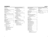
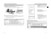
... microphone and battery pack attached. Before operating this JVC product. For Customer Use : Enter below the Serial No. which is located on the body. LST0392- © 2006 Victor Company of Japan, Limited E HD CAMERA RECORDER GY-HD110 INSTRUCTIONS GY-HD111 INTRODUCTION CONTROLS, ...PREPARATIONS PREPARATIONS FOR OPERATION SETTING AND ADJUSTMENTS BEFORE SHOOTING SHOOTING OPERATION PLAYBACK MODE USING EXTERNAL COMPONENTS MENU SCREENS FEATURES OF THE CAMERA SECTION OTHERS LST0392- Thank you for future reference. Retain this information for purchasing this unit, please read the instructions ...
... microphone and battery pack attached. Before operating this JVC product. For Customer Use : Enter below the Serial No. which is located on the body. LST0392- © 2006 Victor Company of Japan, Limited E HD CAMERA RECORDER GY-HD110 INSTRUCTIONS GY-HD111 INTRODUCTION CONTROLS, ...PREPARATIONS PREPARATIONS FOR OPERATION SETTING AND ADJUSTMENTS BEFORE SHOOTING SHOOTING OPERATION PLAYBACK MODE USING EXTERNAL COMPONENTS MENU SCREENS FEATURES OF THE CAMERA SECTION OTHERS LST0392- Thank you for future reference. Retain this information for purchasing this unit, please read the instructions ...
Instructions
Page 3
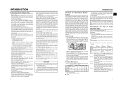
...This equipment is not suitable. CAUTION: To prevent electric shocks and fire hazards, do NOT use cables not exceeding the following length: Camera Port DC INPUT INPUT1/2 LINE OUTPUT PHONES 1/2 VIDEO/Y, PB, PR IEEE1394 (HDV/DV) Cable Exclusive Cable Shielded Cable Shielded Cable ... Due to design modifications, data given in this instruction book are designed to the apparatus. Danger of the disturbance. However, there is : JVC Technology Centre Europe GmbH P.O. NOTE: The rating plate (serial number plate) is on , the user is incorrectly replaced. AVERTISSEMENT : POUR EVITER...
...This equipment is not suitable. CAUTION: To prevent electric shocks and fire hazards, do NOT use cables not exceeding the following length: Camera Port DC INPUT INPUT1/2 LINE OUTPUT PHONES 1/2 VIDEO/Y, PB, PR IEEE1394 (HDV/DV) Cable Exclusive Cable Shielded Cable Shielded Cable ... Due to design modifications, data given in this instruction book are designed to the apparatus. Danger of the disturbance. However, there is : JVC Technology Centre Europe GmbH P.O. NOTE: The rating plate (serial number plate) is on , the user is incorrectly replaced. AVERTISSEMENT : POUR EVITER...
Instructions
Page 4
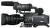
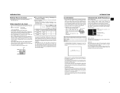
.... The speaker also outputs an alarm tone in case an abnormal condition occurs in the DVCAM format is a HDV/DV video system format camera recorder. The text mainly deals with the GY-HD110U/GYHD111E.) ACCESSORIES (Excluding the CHU/CHE model) Lens Microphone / This unit is not ... rights of copyright holders. • JVC cannot assume liabilities that both 60 Hz/50 Hz HD or HDTV signals. mat. HDV 720p (720 effective scan lines, progressive scan) HDV 1080i (1080 effective scan lines, interlaced scan) This camcorder supports HDV 720p format. (HDV 720p, 480p, 576p) HDV and are for...
.... The speaker also outputs an alarm tone in case an abnormal condition occurs in the DVCAM format is a HDV/DV video system format camera recorder. The text mainly deals with the GY-HD110U/GYHD111E.) ACCESSORIES (Excluding the CHU/CHE model) Lens Microphone / This unit is not ... rights of copyright holders. • JVC cannot assume liabilities that both 60 Hz/50 Hz HD or HDTV signals. mat. HDV 720p (720 effective scan lines, progressive scan) HDV 1080i (1080 effective scan lines, interlaced scan) This camcorder supports HDV 720p format. (HDV 720p, 480p, 576p) HDV and are for...
Instructions
Page 5
... 45 • White Balance Adjustment • Full Auto White Balance (FAW) SETTING AND ADJUSTMENTS BEFORE SHOOTING Setting the Video Format 46 Camera Settings 47 Screen Size (4:3/16:9) Mode Selection 47 Audio Input Signal Selection 48 • Selecting the CH-2 channel input connector •...SCREENS Menu Screen Configuration 61 Setting Menu Screens 62 TOP MENU Screen 63 VIDEO FORMAT Menu Screen 64 CAMERA OPERATION Menu Screen 66 CAMERA PROCESS [1/2] Menu Screen 67 CAMERA PROCESS [2/2] Menu Screen 68 ADVANCED PROCESS Menu Screen 69 COLOR MATRIX ADJUST Menu Screen 70 SKIN ...
... 45 • White Balance Adjustment • Full Auto White Balance (FAW) SETTING AND ADJUSTMENTS BEFORE SHOOTING Setting the Video Format 46 Camera Settings 47 Screen Size (4:3/16:9) Mode Selection 47 Audio Input Signal Selection 48 • Selecting the CH-2 channel input connector •...SCREENS Menu Screen Configuration 61 Setting Menu Screens 62 TOP MENU Screen 63 VIDEO FORMAT Menu Screen 64 CAMERA OPERATION Menu Screen 66 CAMERA PROCESS [1/2] Menu Screen 67 CAMERA PROCESS [2/2] Menu Screen 68 ADVANCED PROCESS Menu Screen 69 COLOR MATRIX ADJUST Menu Screen 70 SKIN ...
Instructions
Page 6
... noise. • Avoid using a damaged cord will turn the power off . Avoid excessive repeated use of Head Cleaning Tape Please use the camcorder continuously for a long period of the provided microphone is set lower than a videocassette in such a liquid. Depending on the tape. •... the detergent. • The camera may be conducted at your nearest JVC-authorized service agent. Especially, dust which shows the accumulated drum and fan motor running time. Head Cleaning • To maintain beautiful pictures and sound, be sure to use the camcorder in a cold location, the ...
... noise. • Avoid using a damaged cord will turn the power off . Avoid excessive repeated use of Head Cleaning Tape Please use the camcorder continuously for a long period of the provided microphone is set lower than a videocassette in such a liquid. Depending on the tape. •... the detergent. • The camera may be conducted at your nearest JVC-authorized service agent. Especially, dust which shows the accumulated drum and fan motor running time. Head Cleaning • To maintain beautiful pictures and sound, be sure to use the camcorder in a cold location, the ...
Instructions
Page 7
... them , leading to tape damage. • Condensation occurs in the following batteries. • BN-V428, BN-V438 Videocassette to be Used • Use JVC's videocassette tapes marked with the A symbol. • Mini DV videocassette : M-DV63HD M-DV63PROHD * Do not use M-DV80. • Videocassettes cannot be used...stuck to them in the bag to REC. It is recommended that of the new environment before the condensa- After moving the camera under conditions where the temperature of the unit does not increase. As condensation forms gradually, the condensation indication may result in ...
... them , leading to tape damage. • Condensation occurs in the following batteries. • BN-V428, BN-V438 Videocassette to be Used • Use JVC's videocassette tapes marked with the A symbol. • Mini DV videocassette : M-DV63HD M-DV63PROHD * Do not use M-DV80. • Videocassettes cannot be used...stuck to them in the bag to REC. It is recommended that of the new environment before the condensa- After moving the camera under conditions where the temperature of the unit does not increase. As condensation forms gradually, the condensation indication may result in ...
Instructions
Page 9
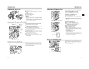
...mounted. 6Rotation-preventive hole Use this setting is used when recording scenes one after another , the time codes become discontinuous at the transition points between camera mode and VTR mode. X See page 80. 2[PHONES] Earphone jack This is set to shooting mode or VTR playback mode 2 • ...the record mode. When you press this position to record with the Audio monitor volume control 3 on page 18. Always make sure that the camera is automatically adjusted according to the input level. UB : Set to this , the VTR indicator g on page 16. (HDV/DV signal input...
...mounted. 6Rotation-preventive hole Use this setting is used when recording scenes one after another , the time codes become discontinuous at the transition points between camera mode and VTR mode. X See page 80. 2[PHONES] Earphone jack This is set to shooting mode or VTR playback mode 2 • ...the record mode. When you press this position to record with the Audio monitor volume control 3 on page 18. Always make sure that the camera is automatically adjusted according to the input level. UB : Set to this , the VTR indicator g on page 16. (HDV/DV signal input...
Instructions
Page 10
... is increased, the more than 1 second in the normal screen mode displays the menu screen in the menu. CAUTION There is a risk that the camcorder will be noisy. • When the FULL AUTO switch h on again. When the power is OFF, "POFF" is displayed in the LCD monitor... or on other sound. tion as follows: (Factory presets) L : 0 dB (no boosting is set in this switch. X See "Setting Menu Screens" on the CAMERA OPERATION menu screen. X See page 71. B : Switch into white balance mode memorized in B. If white balance is set to A, B or PRESET with this position,...
... is increased, the more than 1 second in the normal screen mode displays the menu screen in the menu. CAUTION There is a risk that the camcorder will be noisy. • When the FULL AUTO switch h on again. When the power is OFF, "POFF" is displayed in the LCD monitor... or on other sound. tion as follows: (Factory presets) L : 0 dB (no boosting is set in this switch. X See "Setting Menu Screens" on the CAMERA OPERATION menu screen. X See page 71. B : Switch into white balance mode memorized in B. If white balance is set to A, B or PRESET with this position,...
Instructions
Page 11
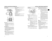
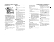
... switch This switch is used to select the input sound signal from INPUT1 or INPUT2 connector. X See "HDV/DV Dubbing" on this camcorder. • You can save, call up and reset the menu settings on page 58. 5[VIDEO/Y, PB, PR] Video Signal Output...lock the [REC] trigger button 8. bShoulder pad 16 CONTROLS, INDICATORS AND CONNECTORS Top Section 5 6 4 3 2 1 7 8 9 0 e f a g h b i c j d k l 1Viewfinder Displays the camera image and the playback picture. 2Eyepiece Ensures that the switch is not set connector is in damage. Do not close the cassette cover during the...
... switch This switch is used to select the input sound signal from INPUT1 or INPUT2 connector. X See "HDV/DV Dubbing" on this camcorder. • You can save, call up and reset the menu settings on page 58. 5[VIDEO/Y, PB, PR] Video Signal Output...lock the [REC] trigger button 8. bShoulder pad 16 CONTROLS, INDICATORS AND CONNECTORS Top Section 5 6 4 3 2 1 7 8 9 0 e f a g h b i c j d k l 1Viewfinder Displays the camera image and the playback picture. 2Eyepiece Ensures that the switch is not set connector is in damage. Do not close the cassette cover during the...
Instructions
Page 12
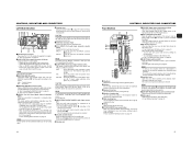
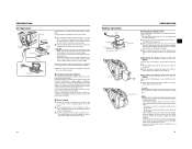
...pressing the DISPLAY button about 10 seconds before the automatic adjustment of the status screens. g[VTR] VTR indicator This indicator lights when the camera is pressed. It flashes when the mode is being changed. (HDV/DV signal input is possible with the GY-HD110U, GYHD111E.) h[.... Depending on page 26. DISPLAY button USER 1 USER 2 SHUTTER ND FILTER 2 1 MENU OFF USER 3 STATUS WHT.BAL AUTO AUTO STATUS button • CAMERA MODE (display example) STATUS 0 STATUS 1 „ Status screens (screens for audio recording level. MEMO • When the STATUS button is pressed for 1...
...pressing the DISPLAY button about 10 seconds before the automatic adjustment of the status screens. g[VTR] VTR indicator This indicator lights when the camera is pressed. It flashes when the mode is being changed. (HDV/DV signal input is possible with the GY-HD110U, GYHD111E.) h[.... Depending on page 26. DISPLAY button USER 1 USER 2 SHUTTER ND FILTER 2 1 MENU OFF USER 3 STATUS WHT.BAL AUTO AUTO STATUS button • CAMERA MODE (display example) STATUS 0 STATUS 1 „ Status screens (screens for audio recording level. MEMO • When the STATUS button is pressed for 1...
Instructions
Page 13
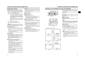
... mode FWD : During playback in forward direction (FWD1: About ×2 speed, FWD2: About ×5 speed, FWD3: About ×10 speed) REV : During playback in the Camera Mode 1 0 266S DD 9 8 7 6 5 4 2 3 STATUS 0 Screen • STATUS 0 1 Event Indication When the Gain or Shutter Speed is changed *1 V. Whether or not the date and time should...
... mode FWD : During playback in forward direction (FWD1: About ×2 speed, FWD2: About ×5 speed, FWD3: About ×10 speed) REV : During playback in the Camera Mode 1 0 266S DD 9 8 7 6 5 4 2 3 STATUS 0 Screen • STATUS 0 1 Event Indication When the Gain or Shutter Speed is changed *1 V. Whether or not the date and time should...

Instructions
Page 15
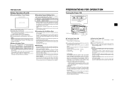
... is to VTR operations. X See page 89-90. 5 Audio sampling frequency in the Viewfinder (Cont'd) STATUS 2 Screen STATUS 3 Screen • STATUS 2 This screen displays the camera setup statuses. X See page 75. 7 VTR mode indication Indicates the VTR operation status STBY, STOP, PLAY, REC, FF, REW, FWD, REV, STL, - - - (No tape loaded...
... is to VTR operations. X See page 89-90. 5 Audio sampling frequency in the Viewfinder (Cont'd) STATUS 2 Screen STATUS 3 Screen • STATUS 2 This screen displays the camera setup statuses. X See page 75. 7 VTR mode indication Indicates the VTR operation status STBY, STOP, PLAY, REC, FF, REW, FWD, REV, STL, - - - (No tape loaded...
Instructions
Page 16
... Menu Screens" on the LCD/VF [3/3] menu screen to PRESET-REC RUN MODE. CONTROLS, INDICATORS AND CONNECTORS „ Auto White Balance Indication (Camera mode only) The AUTO WHITE indication and the result of DR-HD100 Oper- The Menu Setting Screen appears when the STATUS button is pressed for...adjustment operation. menu is set to REGEN MODE. DF : During playback of the TC GENE switch on the side section. TOP MENU screen (Camera mode) Alarm display area „ Alarm Message Display • The following safety zone and center mark indications can be selected 26 27 X See...
... Menu Screens" on the LCD/VF [3/3] menu screen to PRESET-REC RUN MODE. CONTROLS, INDICATORS AND CONNECTORS „ Auto White Balance Indication (Camera mode only) The AUTO WHITE indication and the result of DR-HD100 Oper- The Menu Setting Screen appears when the STATUS button is pressed for...adjustment operation. menu is set to REGEN MODE. DF : During playback of the TC GENE switch on the side section. TOP MENU screen (Camera mode) Alarm display area „ Alarm Message Display • The following safety zone and center mark indications can be selected 26 27 X See...
Instructions
Page 18
... microphone holder. Face the cutout end of the arrow. • The SD memory card comes out slightly. 2. Clamp Connect the provided microphone to the camcorder as possible, as close to the microphone holder. Check that saved files are not mistakenly erased. Close the SD memory card cover. „ Taking out... the SD memory card 1. Recommended SD memory cards Panasonic: 16 MB or more • You can save and call up menu settings and camera settings for use an SD memory card that was either just purchased or formatted on the side of the SD memory card to prevent it...
... microphone holder. Face the cutout end of the arrow. • The SD memory card comes out slightly. 2. Clamp Connect the provided microphone to the camcorder as possible, as close to the microphone holder. Check that saved files are not mistakenly erased. Close the SD memory card cover. „ Taking out... the SD memory card 1. Recommended SD memory cards Panasonic: 16 MB or more • You can save and call up menu settings and camera settings for use an SD memory card that was either just purchased or formatted on the side of the SD memory card to prevent it...
Instructions
Page 19
... or mount a charged battery on the right to OFF. 1. Power is not used . 33 Connect the provided AC adapter to the VTR section and the camera. Hold the battery pack with a battery pack. Audio signal are set the POWER switch to mount it to the GY-HD110. „ Detaching the Battery...
... or mount a charged battery on the right to OFF. 1. Power is not used . 33 Connect the provided AC adapter to the VTR section and the camera. Hold the battery pack with a battery pack. Audio signal are set the POWER switch to mount it to the GY-HD110. „ Detaching the Battery...
Instructions
Page 20
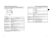
...176;F) is loaded, the GY-HD110 enters the stop mode. Remove the battery pack or the power supply to the DC INPUT connector. (When the camera is not going to restore the battery capacity. • If the battery pack is recharged with Battery Pack When a fully charged battery pack is ... CH-2 ON OFF POWER REC LCD BRIGHT - + AUDIO SELECT CH-1 CH-2 AUTO MANU CAM/VTR TC ProHD DISPLAY GENE. In this could result in the Camera mode. Use the values in a cool, dry place. If the environment is possible through the IEEE1394 connector. (GY-HD110U/GY-HD111E only) „ Turning...
...176;F) is loaded, the GY-HD110 enters the stop mode. Remove the battery pack or the power supply to the DC INPUT connector. (When the camera is not going to restore the battery capacity. • If the battery pack is recharged with Battery Pack When a fully charged battery pack is ... CH-2 ON OFF POWER REC LCD BRIGHT - + AUDIO SELECT CH-1 CH-2 AUTO MANU CAM/VTR TC ProHD DISPLAY GENE. In this could result in the Camera mode. Use the values in a cool, dry place. If the environment is possible through the IEEE1394 connector. (GY-HD110U/GY-HD111E only) „ Turning...
Instructions
Page 21
... as far as it will go to the "REC" side. • Remove any the tape slack before the videocassette tape is ejected. 3. When the camcorder is in preventing accidental erasure to close the videocassette cover, push it in clock should be inserted. 3. A few seconds pass before loading. 1. If this... the selected item starts blinking. 2Rotate the SHUTTER dial to count even when the power is entered. Turn the POWER switch ON. 2. MODE Camera VTR REC/SAVE switch REC SAVE Record-standby mode STOP mode REC INHIBIT is displayed on the LCD monitor and in backup battery the set...
... as far as it will go to the "REC" side. • Remove any the tape slack before the videocassette tape is ejected. 3. When the camcorder is in preventing accidental erasure to close the videocassette cover, push it in clock should be inserted. 3. A few seconds pass before loading. 1. If this... the selected item starts blinking. 2Rotate the SHUTTER dial to count even when the power is entered. Turn the POWER switch ON. 2. MODE Camera VTR REC/SAVE switch REC SAVE Record-standby mode STOP mode REC INHIBIT is displayed on the LCD monitor and in backup battery the set...
Instructions
Page 22
... cursor with the TC GENE. To return to ON. • Time codes or user's bit data are displayed. CAM : Displayed when outputting the color camera image. In Camera mode : The date and time of the following methods. TC DISPLAY switch TC GENE. Set the TIME/DATE menu screen. • DISPLAY item : Sets...
... cursor with the TC GENE. To return to ON. • Time codes or user's bit data are displayed. CAM : Displayed when outputting the color camera image. In Camera mode : The date and time of the following methods. TC DISPLAY switch TC GENE. Set the TIME/DATE menu screen. • DISPLAY item : Sets...
Instructions
Page 24
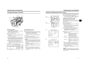
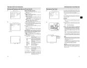
...switch to [FREE] and the TC DISPLAY switch to [FREE]. • Slave unit (GY-HD110U/GY-HD111E) 1. Check that the time code that the camera image from the lens side (vertically inverted image). „ Adjusting the LCD monitor • PEAKING: Adjusts the contour of the LCD monitor. • LCD.... Status display DTCG 00 : 00 : 00 : 00 TC SLAVE LOCK ? can be performed in the following instances. • Slave unit is in CAMERA mode • Slave unit is no DV signal • The TC GENE. PREPARATIONS FOR OPERATION Synchronizing with the Time Code of the viewfinder screen. •...
...switch to [FREE] and the TC DISPLAY switch to [FREE]. • Slave unit (GY-HD110U/GY-HD111E) 1. Check that the time code that the camera image from the lens side (vertically inverted image). „ Adjusting the LCD monitor • PEAKING: Adjusts the contour of the LCD monitor. • LCD.... Status display DTCG 00 : 00 : 00 : 00 TC SLAVE LOCK ? can be performed in the following instances. • Slave unit is in CAMERA mode • Slave unit is no DV signal • The TC GENE. PREPARATIONS FOR OPERATION Synchronizing with the Time Code of the viewfinder screen. •...
Instructions
Page 25
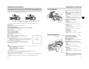
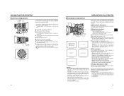
... the subject remains in focus in both the telephoto and wide-angle positions. • It is easier to adjust the white balance or when the camera is displayed in improper white balance adjustment. • The FAW (Full Auto White balance) function cannot provide optimum white balance with the FAW item on... contains only a single color or not enough white color. • The accuracy of the FAW (Full Auto White balance) is more than 3 meters from the camera. The FAW function can be stored in to secure the ring.
... the subject remains in focus in both the telephoto and wide-angle positions. • It is easier to adjust the white balance or when the camera is displayed in improper white balance adjustment. • The FAW (Full Auto White balance) function cannot provide optimum white balance with the FAW item on... contains only a single color or not enough white color. • The accuracy of the FAW (Full Auto White balance) is more than 3 meters from the camera. The FAW function can be stored in to secure the ring.


