
Instruction Manual
Page 9
... Power 30 Using a Battery Pack 31 Power Status Display 32 Turning On/Off the Power 33 Initial Settings 34 Displays on the LCD Monitor and Viewfinder .. 36 Display Screen 36 Status Screen 37 USB Mode Screen 38 Remote Edit Mode Screen 38 Warning Display 38 Adjusting the LCD Monitor and Viewfinder ...... 38 Adjusting the LCD Monitor 39 Adjusting the Viewfinder 40 Adjusting the Monitor Speaker 40 Adjusting Back Focus 41 Assignment of Functions to User Buttons ........ 42 Tally Lamp 42 SD Card...
... Power 30 Using a Battery Pack 31 Power Status Display 32 Turning On/Off the Power 33 Initial Settings 34 Displays on the LCD Monitor and Viewfinder .. 36 Display Screen 36 Status Screen 37 USB Mode Screen 38 Remote Edit Mode Screen 38 Warning Display 38 Adjusting the LCD Monitor and Viewfinder ...... 38 Adjusting the LCD Monitor 39 Adjusting the Viewfinder 40 Adjusting the Monitor Speaker 40 Adjusting Back Focus 41 Assignment of Functions to User Buttons ........ 42 Tally Lamp 42 SD Card...

Instruction Manual
Page 10
...Menu 143 Display/Status Screen Display Screen in Camera Mode 145 Display Screen in Media Mode 151 Status Screen 153 Camera Features Marker and Safety Zone Displays 154 Smoothening the Skin Color (Skin Detail Function 155 Color Bar Output 155 Adjusting Color Matrix 156 Configuring Setup Files 157 Saving Setup Files 157 Loading a Setup File 158 Deleting Setup Files 159 Connecting External Devices Managing/Editing Clips on a PC 160 Connecting External Monitor 161 Connecting a Earphone 163 Connecting Wired Remote Control 164 Connecting a Remote Control Unit 164 Functions Operable...
...Menu 143 Display/Status Screen Display Screen in Camera Mode 145 Display Screen in Media Mode 151 Status Screen 153 Camera Features Marker and Safety Zone Displays 154 Smoothening the Skin Color (Skin Detail Function 155 Color Bar Output 155 Adjusting Color Matrix 156 Configuring Setup Files 157 Saving Setup Files 157 Loading a Setup File 158 Deleting Setup Files 159 Connecting External Devices Managing/Editing Clips on a PC 160 Connecting External Monitor 161 Connecting a Earphone 163 Connecting Wired Remote Control 164 Connecting a Remote Control Unit 164 Functions Operable...

Instruction Manual
Page 13
... file transfer as digital output. Main Features 13 Built-in GPS This camera recorder is provided for you to copy recorded clips to Windows or Macintosh computers and for checking the video images. (For MP4 file format) The disc provided with this unit via a network by broadcasting stations, such as Anton/ Bauer and IDX batteries. (Gold Mount: For use with a USB host function, you can also record audio input from the [AUX] input...
... file transfer as digital output. Main Features 13 Built-in GPS This camera recorder is provided for you to copy recorded clips to Windows or Macintosh computers and for checking the video images. (For MP4 file format) The disc provided with this unit via a network by broadcasting stations, such as Anton/ Bauer and IDX batteries. (Gold Mount: For use with a USB host function, you can also record audio input from the [AUX] input...

Instruction Manual
Page 16
... on the SD cards. In this case, format (initialize) the SD card on the SD card is being removed. Be careful not to the terminals. . Some recording formats supports only the use or store the SD card in red when data on this manual. o Do not use of use pencils or ballpoint pens to write on the card, including video data and setup files, will be deleted. o Make use of the SD...
... on the SD cards. In this case, format (initialize) the SD card on the SD card is being removed. Be careful not to the terminals. . Some recording formats supports only the use or store the SD card in red when data on this manual. o Do not use of use pencils or ballpoint pens to write on the card, including video data and setup files, will be deleted. o Make use of the SD...

Instruction Manual
Page 19
...USB cable is connected during recording, the message appears after recording stops. 0 If playback is connected to a USB cable, the message "Change to USB Mode?" appears on the camera recorder and pressing the Set button switches to Remote Edit Mode?" "STBY" appears on the operation mode display area of the recorded clip data through access to play back or delete clips recorded on the viewfinder and LCD monitor. Introduction Operation Mode Camera Mode Media Mode USB Mode Remote Edit Mode Description 0 This is displayed on the viewfinder and LCD monitor. 0 Press and hold the [CAM...
...USB cable is connected during recording, the message appears after recording stops. 0 If playback is connected to a USB cable, the message "Change to USB Mode?" appears on the camera recorder and pressing the Set button switches to Remote Edit Mode?" "STBY" appears on the operation mode display area of the recorded clip data through access to play back or delete clips recorded on the viewfinder and LCD monitor. Introduction Operation Mode Camera Mode Media Mode USB Mode Remote Edit Mode Description 0 This is displayed on the viewfinder and LCD monitor. 0 Press and hold the [CAM...

Instruction Manual
Page 20
...Set Button (R) The function changes according to this unit is not displayed). F You can also use ZEBRA][8/I [FULL AUTO ON/OFF] Full Auto Switch (A P57 [Adjusting the Brightness Automatically] ) (A P65 [Automatic White Balance Mode (FAW: Fulltime Auto White balance)] ) 20 Names of Parts O NM L A B K J Introduction FG HI C DE . H [CAM/MEDIA] Camera/Media Mode Selection Button (A P18 [Operation Modes] ) I /SPOT it as a user button METER] by assigning a specific feature in the menu setting to this button. (A P42 [Assignment of Functions to User Buttons] ) (A P79 [Setting...
...Set Button (R) The function changes according to this unit is not displayed). F You can also use ZEBRA][8/I [FULL AUTO ON/OFF] Full Auto Switch (A P57 [Adjusting the Brightness Automatically] ) (A P65 [Automatic White Balance Mode (FAW: Fulltime Auto White balance)] ) 20 Names of Parts O NM L A B K J Introduction FG HI C DE . H [CAM/MEDIA] Camera/Media Mode Selection Button (A P18 [Operation Modes] ) I /SPOT it as a user button METER] by assigning a specific feature in the menu setting to this button. (A P42 [Assignment of Functions to User Buttons] ) (A P79 [Setting...

Instruction Manual
Page 26
... This is set the [ZOOM SERVO/MANUAL] switch H to "SERVO". J [REC] Record Trigger Button Starts/stops recording. K [RET] Return Video Button Functions as a user button by assigning a specific feature in the following cases. 0 When using a zoom servo unit (sold separately) 0 When operating remotely from a remote control unit connected to the [REMOTE1]/ [REMOTE2] terminal or from a web browser (A P52 [Zoom Operation] ) I Lens Cable For connecting to the camera's [LENS] connection terminal. Select "A" to set to auto iris, and "M" to set the [IRIS A/M] mode switch M to manual iris...
... This is set the [ZOOM SERVO/MANUAL] switch H to "SERVO". J [REC] Record Trigger Button Starts/stops recording. K [RET] Return Video Button Functions as a user button by assigning a specific feature in the following cases. 0 When using a zoom servo unit (sold separately) 0 When operating remotely from a remote control unit connected to the [REMOTE1]/ [REMOTE2] terminal or from a web browser (A P52 [Zoom Operation] ) I Lens Cable For connecting to the camera's [LENS] connection terminal. Select "A" to set to auto iris, and "M" to set the [IRIS A/M] mode switch M to manual iris...

Instruction Manual
Page 31
..." sound is connected to the [instruction manual] of the battery in battery always gets charged. Attaching/Detaching the Battery (U Model) Use the Dionic90 (Anton/Bauer) battery. 1 Align the battery guide pins (x3) with the battery adapter guide hole, and insert them directly. When the power is not applicable. Battery Continuous Recording Time (At 25 °C) Dionic90 (U model) Approx. 2.8 h Endura-HL9 (E model) Approx. 2.7 h Memo : 0 Actual operating times may differ depending on fully-charged batteries. Caution : 0 Make use . 0 Leaving the camera recorder...
..." sound is connected to the [instruction manual] of the battery in battery always gets charged. Attaching/Detaching the Battery (U Model) Use the Dionic90 (Anton/Bauer) battery. 1 Align the battery guide pins (x3) with the battery adapter guide hole, and insert them directly. When the power is not applicable. Battery Continuous Recording Time (At 25 °C) Dionic90 (U model) Approx. 2.8 h Endura-HL9 (E model) Approx. 2.7 h Memo : 0 Actual operating times may differ depending on fully-charged batteries. Caution : 0 Make use . 0 Leaving the camera recorder...

Instruction Manual
Page 33
... or playback screen is displayed on the operation mode display area of the camera recorder appear blinking. 0 The warning tone is output from the monitor speaker or [PHONES] terminal. Accurate data may not be displayed depending on the viewfinder and LCD monitor. Camera Mode Camera images are from the battery information. Memo : 0 If you to connect to a PC and transfer the files on the SD card. Turning On/Off the Power Turning On the Power 1 Set the [POWER...
... or playback screen is displayed on the operation mode display area of the camera recorder appear blinking. 0 The warning tone is output from the monitor speaker or [PHONES] terminal. Accurate data may not be displayed depending on the viewfinder and LCD monitor. Camera Mode Camera images are from the battery information. Memo : 0 If you to connect to a PC and transfer the files on the SD card. Turning On/Off the Power Turning On the Power 1 Set the [POWER...

Instruction Manual
Page 70
... camera recorder even when the [FULL AUTO] switch is set automatically according to be adjusted manually. 2 Turn the [AUDIO LEVEL CH-1/CH-2] adjustment knob corresponding to the channel to adjust the level. Memo : 0 When the [FULL AUTO] switch is set to "ON", mode switching of the [AUDIO SELECT CH-1/ CH-2 AUTO/MANUAL] selection switch is disabled. 0 When [Main Menu] B [A/V Set] B [Audio Set] B [CH1 Limiter]/[CH2 Limiter] B [Threshold Level] is set . 0 You can switch the audio recording mode with the [AUDIO SELECT CH-1/CH-2 AUTO/MANUAL] selection switch...
... camera recorder even when the [FULL AUTO] switch is set automatically according to be adjusted manually. 2 Turn the [AUDIO LEVEL CH-1/CH-2] adjustment knob corresponding to the channel to adjust the level. Memo : 0 When the [FULL AUTO] switch is set to "ON", mode switching of the [AUDIO SELECT CH-1/ CH-2 AUTO/MANUAL] selection switch is disabled. 0 When [Main Menu] B [A/V Set] B [Audio Set] B [CH1 Limiter]/[CH2 Limiter] B [Threshold Level] is set . 0 You can switch the audio recording mode with the [AUDIO SELECT CH-1/CH-2 AUTO/MANUAL] selection switch...
Instruction Manual
Page 75
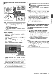
... GENE.] switch is set to "REGEN". 0 Menu screen is displayed. 0 The camera recorder is set in [Main Menu] B [Camera Function] B [User Switch Set] is disabled. [MARKER/2] functions as the number reset button. (A P111 [User Switch Set Item] ) Recording Time Code in Continuation of the Recorded Time Code on SD Card This camera recorder is equipped with the time code reader. 1 Set the [TC GENE.] switch to "REGEN". 0 When the camera recorder enters from recording standby mode to recording mode, it reads the time code already recorded on the SD card and records the new time code in continuation...
... GENE.] switch is set to "REGEN". 0 Menu screen is displayed. 0 The camera recorder is set in [Main Menu] B [Camera Function] B [User Switch Set] is disabled. [MARKER/2] functions as the number reset button. (A P111 [User Switch Set Item] ) Recording Time Code in Continuation of the Recorded Time Code on SD Card This camera recorder is equipped with the time code reader. 1 Set the [TC GENE.] switch to "REGEN". 0 When the camera recorder enters from recording standby mode to recording mode, it reads the time code already recorded on the SD card and records the new time code in continuation...

Instruction Manual
Page 83
... operate Clip Review, use the [CANCEL] button to set to "STBYC" (white text) first. (A P89 [Clip Continuous Rec] ) 0 Clip Review is unavailable when the camera recorder is connected to User Buttons] ) 2 Press the button assigned with the "Clip Review" function during standby ("STBY" is played back according to cancel clip review and enter recording mode. Memo : 0 The video clip is displayed). Press the [REC] button to the setting in the selected slot, Clip Review function is disabled. 0 Clip Review...
... operate Clip Review, use the [CANCEL] button to set to "STBYC" (white text) first. (A P89 [Clip Continuous Rec] ) 0 Clip Review is unavailable when the camera recorder is connected to User Buttons] ) 2 Press the button assigned with the "Clip Review" function during standby ("STBY" is played back according to cancel clip review and enter recording mode. Memo : 0 The video clip is displayed). Press the [REC] button to the setting in the selected slot, Clip Review function is disabled. 0 Clip Review...
Instruction Manual
Page 128
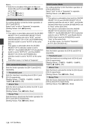
... the limiter operation for [CH-3] and [CH-4] respectively. [Setting Values: Fast, RMiddle, Slow] 128 A/V Set Menu Select "Link" to link or "Separate" to separate. [Setting Values: Link, RSeparate] Memo : 0 This option is selectable when both the [AUDIO SELECT CH-1] and [AUDIO SELECT CH-2] selection switches are set to "AUX", and [Audio Set] B [CH3/4 Input Level] B [CH3]/[CH4] is set to "AUTO" at the same time. Select "Link...
... the limiter operation for [CH-3] and [CH-4] respectively. [Setting Values: Fast, RMiddle, Slow] 128 A/V Set Menu Select "Link" to link or "Separate" to separate. [Setting Values: Link, RSeparate] Memo : 0 This option is selectable when both the [AUDIO SELECT CH-1] and [AUDIO SELECT CH-2] selection switches are set to "AUX", and [Audio Set] B [CH3/4 Input Level] B [CH3]/[CH4] is set to "AUTO" at the same time. Select "Link...

Instruction Manual
Page 170
... screen. 0 After locking to reasons such as no signal input while genlock is in the [Record Format] menu is not a malfunction. 0 Signals such as when composite signals are used SD synchronizing : Supports SMPTE259M signal HD synchronizing : Supports SMPTE292M signal HD/SD SDI IN External Synchronizing Signal SDI Signal Generator Connecting External Devices . 170 Inputting External Synchronizing Signals (Genlock) 1 Set the camera recorder to the Camera mode. (A P18 [Operation Modes] ) 2 Set [Genlock Input] to input...
... screen. 0 After locking to reasons such as no signal input while genlock is in the [Record Format] menu is not a malfunction. 0 Signals such as when composite signals are used SD synchronizing : Supports SMPTE259M signal HD synchronizing : Supports SMPTE292M signal HD/SD SDI IN External Synchronizing Signal SDI Signal Generator Connecting External Devices . 170 Inputting External Synchronizing Signals (Genlock) 1 Set the camera recorder to the Camera mode. (A P18 [Operation Modes] ) 2 Set [Genlock Input] to input...

Instruction Manual
Page 171
.... This is displayed. 1 Set the camera recorder to the Camera mode. (A P18 [Operation Modes] ) 2 Set [Genlock Input] to the external synchronizing signal, "Sync Locking" appears on the input synchronizing signal and output video signal. It does not come with respect to the external synchronizing signal is in progress. 0 The video image may vary depending on the screen. 0 After locking to the external synchronizing signal input from the accessory connection terminal (68...
.... This is displayed. 1 Set the camera recorder to the Camera mode. (A P18 [Operation Modes] ) 2 Set [Genlock Input] to the external synchronizing signal, "Sync Locking" appears on the input synchronizing signal and output video signal. It does not come with respect to the external synchronizing signal is in progress. 0 The video image may vary depending on the screen. 0 After locking to the external synchronizing signal input from the accessory connection terminal (68...
Instruction Manual
Page 177
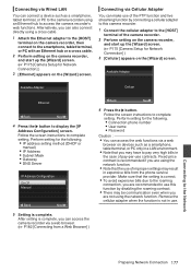
... [Camera Setup for the following . 0 Connection phone number 0 User name 0 Password Caution : 0 You can access the web functions via a web browser on devices such as a smartphone, tablet terminal, or PC to the camera recorder using an Ethernet hub to display the [IP Address Configuration] screen. Remove the cellular adapter when the function is complete. Ethernet Back Next 4 Press the I button. Perform setting for Network Connection] ) 3 [Cellular] appears on the [Wizard] screen. Fixed...
... [Camera Setup for the following . 0 Connection phone number 0 User name 0 Password Caution : 0 You can access the web functions via a web browser on devices such as a smartphone, tablet terminal, or PC to the camera recorder using an Ethernet hub to display the [IP Address Configuration] screen. Remove the cellular adapter when the function is complete. Ethernet Back Next 4 Press the I button. Perform setting for Network Connection] ) 3 [Cellular] appears on the [Wizard] screen. Fixed...
Instruction Manual
Page 200
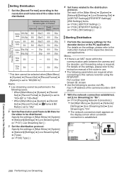
... 0 Use the following cases. 0 When [Main Menu] B [System] B [Record Set] B [Record Format] B [System] is set to "HD+SD" or "HD+Web" 0 When [Main Menu] B [System] B [Record Set] B [Record Format] B [WFrame & Bit Rate] is set [Live Streaming] to "On". (A P174 [Preparing Network Connection] ) 0 Set [Main Menu] B [System] B [Network]/ [Settings] B [Live Streaming Set] B [Live Streaming] to "On". 0 The network connection mark appears on the settings, please refer to the instruction manual of the [Main Menu...
... 0 Use the following cases. 0 When [Main Menu] B [System] B [Record Set] B [Record Format] B [System] is set to "HD+SD" or "HD+Web" 0 When [Main Menu] B [System] B [Record Set] B [Record Format] B [WFrame & Bit Rate] is set [Live Streaming] to "On". (A P174 [Preparing Network Connection] ) 0 Set [Main Menu] B [System] B [Network]/ [Settings] B [Live Streaming Set] B [Live Streaming] to "On". 0 The network connection mark appears on the settings, please refer to the instruction manual of the [Main Menu...

Instruction Manual
Page 202
... as follows according to the error status. Error Message Status Action Turn Power Off Turn Back On System error. Usage time of the fan in progress. 0 Card is removed while adding the OK mark. 0 Card is removed while writing a setup file. 0 Card is in progress. For more details, please consult your nearest service center. accordingly. the SD Card] ) 0 Card is removed while restoring is set. Rec Inhibited [REC] button is pressed when the...
... as follows according to the error status. Error Message Status Action Turn Power Off Turn Back On System error. Usage time of the fan in progress. 0 Card is removed while adding the OK mark. 0 Card is removed while writing a setup file. 0 Card is in progress. For more details, please consult your nearest service center. accordingly. the SD Card] ) 0 Card is removed while restoring is set. Rec Inhibited [REC] button is pressed when the...
Instruction Manual
Page 203
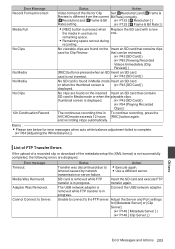
... Card] ) (A P94 [Playing Recorded Clips] ) 12h Continuation Record The continuous recording time in progress. Media Was Removed. Adapter Was Removed. Status Action Transfer was discontinued due to Server. The USB network adapter is removed while FTP transfer is in To continue recording, press the AVCHD mode exceeds 12 hours [REC] button again. Error message Timeout. SD card is removed while FTP transfer is in use has no one. Error Message Record Format Incorrect Media Full Status Action Video format of the metadata setup file...
... Card] ) (A P94 [Playing Recorded Clips] ) 12h Continuation Record The continuous recording time in progress. Media Was Removed. Adapter Was Removed. Status Action Transfer was discontinued due to Server. The USB network adapter is removed while FTP transfer is in To continue recording, press the AVCHD mode exceeds 12 hours [REC] button again. Error message Timeout. SD card is removed while FTP transfer is in use has no one. Error Message Record Format Incorrect Media Full Status Action Video format of the metadata setup file...
Instruction Manual
Page 208
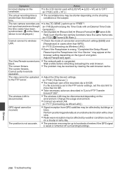
... display on the 0 Is the LCD monitor used with [LCD/VF] B [LCD + VF] set to more than 64 GB. 0 Take necessary action as on the type of encryption. Please Input the Passphrase into Your Device." The screen flickers. Wait a while before refreshing (reloading) the web browser. 0 The problem may be uploaded 0 Adjust the [Clip Server] settings. Cannot perform remote operation. If a file size limit is congested. Others 208 Troubleshooting...
... display on the 0 Is the LCD monitor used with [LCD/VF] B [LCD + VF] set to more than 64 GB. 0 Take necessary action as on the type of encryption. Please Input the Passphrase into Your Device." The screen flickers. Wait a while before refreshing (reloading) the web browser. 0 The problem may be uploaded 0 Adjust the [Clip Server] settings. Cannot perform remote operation. If a file size limit is congested. Others 208 Troubleshooting...


