

Instruction Manual
Page 4
... ● Camera section designed with DV connector, such as you for private use may infringe on the rights of copyright holders. ● JVC cannot assume liabilities that both video ... concentrated LCD panel shows the time code and CTL counter, tape remaining time, remaining battery power, audio levels, VCR section setup menus, hour meter data, and a variety ...between indoors and outdoors or between scenes recorded on other units (including another GY-DV550) are for purchasing the DV Camcorder GY-DV550. Videocassettes which varies as a non-linear editing controller. ● S.S.F....
... ● Camera section designed with DV connector, such as you for private use may infringe on the rights of copyright holders. ● JVC cannot assume liabilities that both video ... concentrated LCD panel shows the time code and CTL counter, tape remaining time, remaining battery power, audio levels, VCR section setup menus, hour meter data, and a variety ...between indoors and outdoors or between scenes recorded on other units (including another GY-DV550) are for purchasing the DV Camcorder GY-DV550. Videocassettes which varies as a non-linear editing controller. ● S.S.F....

Instruction Manual
Page 6
...-7 Connecting the Local Remote Control Unit 93 13-8 Connecting the Camera Remote Control Unit .......... 94 OTHERS 14. POWER Microphone CR230V32 Lithium battery Head cleaning tape Tripod base CAUTION : ● The front base mount may be avoided as shown below. FEATURES OF THE CAMERA ...Alarm Indications 96 • Warnings in Viewfinder 98 • Troubles with DV Connector 70 11-2 Connecting a PC 71 12. Therefore, after mounting, make sure that these parts are engaged properly. ● When moving the GY-DV550 mounted on a tripod, any impact or vibration should be locked while ...
...-7 Connecting the Local Remote Control Unit 93 13-8 Connecting the Camera Remote Control Unit .......... 94 OTHERS 14. POWER Microphone CR230V32 Lithium battery Head cleaning tape Tripod base CAUTION : ● The front base mount may be avoided as shown below. FEATURES OF THE CAMERA ...Alarm Indications 96 • Warnings in Viewfinder 98 • Troubles with DV Connector 70 11-2 Connecting a PC 71 12. Therefore, after mounting, make sure that these parts are engaged properly. ● When moving the GY-DV550 mounted on a tripod, any impact or vibration should be locked while ...

Instruction Manual
Page 9
...● When condensation occurs in this may cause a jagged effect or a banding in fine mesh patterns. Do not 1-6 Battery Pack to be Used The GY-DV550 can cause CCD sensor pixels to malfunction with unevenly wound tape, as this will reduce the rotary head life. ● ...396 BATTERY TYPE according to the type of light around a bright light or object (called "smear") when shooting an extremely bright light source. This phenomenon is characterized by dropouts, etc. Nevertheless, please be connected directly to the camera. 1-5 Videocassette to be Used ● Use JVC's ...
...● When condensation occurs in this may cause a jagged effect or a banding in fine mesh patterns. Do not 1-6 Battery Pack to be Used The GY-DV550 can cause CCD sensor pixels to malfunction with unevenly wound tape, as this will reduce the rotary head life. ● ...396 BATTERY TYPE according to the type of light around a bright light or object (called "smear") when shooting an extremely bright light source. This phenomenon is characterized by dropouts, etc. Nevertheless, please be connected directly to the camera. 1-5 Videocassette to be Used ● Use JVC's ...

Instruction Manual
Page 15
... when newly presetting and recording the time code. The battery is used for MONITOR OUT and Y/C OUT signals. • To input the image of the DV connector 1 on the tape. * Lithium Battery Installation Compartment Install a lithium battery (CR2032) in continuation of the digit to be set...If this button is pressed simultaneously with an external time code generator. * If this position is set . The GY-DV550 delivered without the battery installed. The provided lithium battery is used to the menu indication. Each press of time code or user's bit cancels the operation and recalls ...
... when newly presetting and recording the time code. The battery is used for MONITOR OUT and Y/C OUT signals. • To input the image of the DV connector 1 on the tape. * Lithium Battery Installation Compartment Install a lithium battery (CR2032) in continuation of the digit to be set...If this button is pressed simultaneously with an external time code generator. * If this position is set . The GY-DV550 delivered without the battery installed. The provided lithium battery is used to the menu indication. Each press of time code or user's bit cancels the operation and recalls ...

Instruction Manual
Page 16
... Normally lights green. This indicator lights or blinks in red in the case of a warning condition related to the remaining tape time, remaining battery power or other abnormal condition in case of the back-lit display ON or OFF. Lights orange during recording and playback. 9 [MENU] indicator...minutes and seconds) is set to display the CTL counter. OFF : The display is not illuminated. (Keep this switch at OFF during presetting of the GY-DV550 or when it is not a malfunction. 6 SP indicator Indicates the tape speed in the NORMAL or LETTER mode. ! "OVER" lights in the ...
... Normally lights green. This indicator lights or blinks in red in the case of a warning condition related to the remaining tape time, remaining battery power or other abnormal condition in case of the back-lit display ON or OFF. Lights orange during recording and playback. 9 [MENU] indicator...minutes and seconds) is set to display the CTL counter. OFF : The display is not illuminated. (Keep this switch at OFF during presetting of the GY-DV550 or when it is not a malfunction. 6 SP indicator Indicates the tape speed in the NORMAL or LETTER mode. ! "OVER" lights in the ...

Instruction Manual
Page 17
...counter, time code or user's bit. The unit rejects all operations while this section shows the data of replacement when the lithium battery that it is not detected during playback and recording check using the provided head cleaning tape. When the condensation has disappeared, the indicator... VCR setup menu data when the GY-DV550 is in the VCR setup menu mode by pressing the HOLD button in the still picture mode. $ Remaining Battery Power Display The 7-dot segment bar display shows the remaining battery power. * To display the remaining battery power accurately, set the VCR Setup...
...counter, time code or user's bit. The unit rejects all operations while this section shows the data of replacement when the lithium battery that it is not detected during playback and recording check using the provided head cleaning tape. When the condensation has disappeared, the indicator... VCR setup menu data when the GY-DV550 is in the VCR setup menu mode by pressing the HOLD button in the still picture mode. $ Remaining Battery Power Display The 7-dot segment bar display shows the remaining battery power. * To display the remaining battery power accurately, set the VCR Setup...

Instruction Manual
Page 27
...EXT F5 . 6 STBY ACCU - The external VCR status is displayed when VTR SELECT switch is set to AUX). One of the status screens in the GY-DV550. Blinks green : • Immediately before the tape is set to recording. • Immediately before the tape is playing back a tape.) Status screens (screens... VCR. These LEDs light or blink to indicate the present status of the camera or the VCR. ● [BATT] battery lamp This lights red when the battery voltage becomes too low for use in the camera and VCR setup) STATUS button Auto white balance display Shutter speed display Status...
...EXT F5 . 6 STBY ACCU - The external VCR status is displayed when VTR SELECT switch is set to AUX). One of the status screens in the GY-DV550. Blinks green : • Immediately before the tape is set to recording. • Immediately before the tape is playing back a tape.) Status screens (screens... VCR. These LEDs light or blink to indicate the present status of the camera or the VCR. ● [BATT] battery lamp This lights red when the battery voltage becomes too low for use in the camera and VCR setup) STATUS button Auto white balance display Shutter speed display Status...

Instruction Manual
Page 32
...information on connection with S14X7.3B12/U. Please use the Focus Manual Unit (FMM-8, CHF-3, CFC-12-990) manufactured by Fujinon. 32 POWER GY-DV550 STANDARD PACKAGE TRIPOD BASE VIDEO LIGHT (ANTON BAUER. 3. LOCAL REMOTE CONTROL UNIT RM-LP55 RM-LP57 ULTRA LIGHT (ANTON BAUER.PROTEC) ...BELT VF HOLDER KA-A40 CAMERA REMOTE CONTROL UNIT RM-P200 RM-P300 BATTERY NP-1B TYPE BATTERY NP-1B TYPE BATTERY CHARGER 1.5" VIEW FINDER VF-P115B VF-P116 DV CAMCORDER BATTERY HOLDER BH-P27 BATTERY NB-G1 NB-G1 (4PACK) BATTERY CHARGER (AC POWER ADAPTER) AA-G11 ZOOM LENS S14 x 7.3B12(FUJINON...
...information on connection with S14X7.3B12/U. Please use the Focus Manual Unit (FMM-8, CHF-3, CFC-12-990) manufactured by Fujinon. 32 POWER GY-DV550 STANDARD PACKAGE TRIPOD BASE VIDEO LIGHT (ANTON BAUER. 3. LOCAL REMOTE CONTROL UNIT RM-LP55 RM-LP57 ULTRA LIGHT (ANTON BAUER.PROTEC) ...BELT VF HOLDER KA-A40 CAMERA REMOTE CONTROL UNIT RM-P200 RM-P300 BATTERY NP-1B TYPE BATTERY NP-1B TYPE BATTERY CHARGER 1.5" VIEW FINDER VF-P115B VF-P116 DV CAMCORDER BATTERY HOLDER BH-P27 BATTERY NB-G1 NB-G1 (4PACK) BATTERY CHARGER (AC POWER ADAPTER) AA-G11 ZOOM LENS S14 x 7.3B12(FUJINON...

Instruction Manual
Page 36
BASIC SYSTEM CONNECTIONS AND ADJUSTMENTS 3-8 Inserting and Replacing Backup Lithium Batteries The GY-DV550 uses a lithium battery for a lengthy period of the arrow as illustrated and remove the cover. 2. If the voltage of the lithium battery at the place indicated in the unit. FILTER 1 3200k ..." indicator in the direction of time (one month or more), remove the lithium battery. Replace lithium batteries with the OPERATE switch set to Install the Lithium Battery Lithium battery cover LITHIUM BATT. Doing it with its original position in the illustration on the ...
BASIC SYSTEM CONNECTIONS AND ADJUSTMENTS 3-8 Inserting and Replacing Backup Lithium Batteries The GY-DV550 uses a lithium battery for a lengthy period of the arrow as illustrated and remove the cover. 2. If the voltage of the lithium battery at the place indicated in the unit. FILTER 1 3200k ..." indicator in the direction of time (one month or more), remove the lithium battery. Replace lithium batteries with the OPERATE switch set to Install the Lithium Battery Lithium battery cover LITHIUM BATT. Doing it with its original position in the illustration on the ...

Instruction Manual
Page 37
... generating noise, such as the AC power supply. rated output 12.5 V DC, 3.5 A) as ripples. AA-P250 AC power adapter DC cable DV LINE EARPHONE DC OUTPUT MIC +48V ON LINE MIC +48V ON FRONT AUDIO IN REAR INTERCOM DC INPUT Precautions for a moment when the DC cable...BATT, and set the POWER switch to mount the optional battery holder. The following battery packs. OPERATE switch POWER switch 4-1 AC Operation Use the JVC AA-P250 AC power adapter (max. Battery holder: Anton-Bauer QRQ27 For details on the GY-DV550 is not going to be supplied through the VTR/RM ...
... generating noise, such as the AC power supply. rated output 12.5 V DC, 3.5 A) as ripples. AA-P250 AC power adapter DC cable DV LINE EARPHONE DC OUTPUT MIC +48V ON LINE MIC +48V ON FRONT AUDIO IN REAR INTERCOM DC INPUT Precautions for a moment when the DC cable...BATT, and set the POWER switch to mount the optional battery holder. The following battery packs. OPERATE switch POWER switch 4-1 AC Operation Use the JVC AA-P250 AC power adapter (max. Battery holder: Anton-Bauer QRQ27 For details on the GY-DV550 is not going to be supplied through the VTR/RM ...

Instruction Manual
Page 39
... Use the following battery holder. • Battery holder: Anton-Bauer QRQ27 Detaching the Battery Case From the GY-DV550 and Attaching The Anton-Bauer Battery 2. Remove the two black screws A on the battery holder, and push straight to pinch the wires. Secure the battery holder to the GY-DV550 with the four mount... the guide pins are not inserted straight. 2. To remove the battery case, remove the four screws B fixing the battery case and the connector connecting the battery case to detach the battery case from the GY-DV550 with display LIGHT ON OFF COUNTER CTL TC UB CH-1 CH-2...
... Use the following battery holder. • Battery holder: Anton-Bauer QRQ27 Detaching the Battery Case From the GY-DV550 and Attaching The Anton-Bauer Battery 2. Remove the two black screws A on the battery holder, and push straight to pinch the wires. Secure the battery holder to the GY-DV550 with the four mount... the guide pins are not inserted straight. 2. To remove the battery case, remove the four screws B fixing the battery case and the connector connecting the battery case to detach the battery case from the GY-DV550 with display LIGHT ON OFF COUNTER CTL TC UB CH-1 CH-2...

Instruction Manual
Page 40
...immediately after completely discharging it. Recharging ● Recharge the battery pack after recharging, the service life of the battery pack in use , it to restore the battery capacity. ● If the battery pack is recharged with a cold environment. ● Operating... the remaining battery power warnings appear, the GY-DV550 automatically stops operation if the battery power operation is not in the table on the number of the remaining battery power can be performed completely. 40 POWER SUPPLY 4-2 Battery Pack Operation (Cont'd) REMAINING BATTERY POWER DISPLAY WARNING...
...immediately after completely discharging it. Recharging ● Recharge the battery pack after recharging, the service life of the battery pack in use , it to restore the battery capacity. ● If the battery pack is recharged with a cold environment. ● Operating... the remaining battery power warnings appear, the GY-DV550 automatically stops operation if the battery power operation is not in the table on the number of the remaining battery power can be performed completely. 40 POWER SUPPLY 4-2 Battery Pack Operation (Cont'd) REMAINING BATTERY POWER DISPLAY WARNING...

Instruction Manual
Page 41
...is displayed on during the following conditions. POWER switch FULL AUTO lamp 2. Select the GY-DV550 operation mode with the POWER switch. • When supplying power to the unit from the DC IN connector or battery, set to the unit from the camera control unit. 2. Do not turn the... ON and when the cassette is displayed in the VCR operation indicating section of the VTR switch as follows: VTR switch setting SAVE STBY GY-DV550 operation mode GY-DV550 enters the SAVE mode (tape protect mode) and stops the drum motor. 5. "SAVE" is loaded depending on . 3. PREPARATIONS 5-1 Turning...
...is displayed on during the following conditions. POWER switch FULL AUTO lamp 2. Select the GY-DV550 operation mode with the POWER switch. • When supplying power to the unit from the DC IN connector or battery, set to the unit from the camera control unit. 2. Do not turn the... ON and when the cassette is displayed in the VCR operation indicating section of the VTR switch as follows: VTR switch setting SAVE STBY GY-DV550 operation mode GY-DV550 enters the SAVE mode (tape protect mode) and stops the drum motor. 5. "SAVE" is loaded depending on . 3. PREPARATIONS 5-1 Turning...

Instruction Manual
Page 54
...lightning conditions of the BACK TALLY lamp on the rear section of the tape, a blank space appears as required. Drum rotation stops and the GY-DV550 enters the tape protection/power-saving mode. 12. Once recording has started, the BACK TALLY lamp on the rear section of the unit and the... being pressed, the viewfinder REC indicator lamp may blink and the GY-DV550 may pick up the sound of recording. If you end a recording by turning the OPERATE switch, POWER switch or DC power supply OFF, or by removing the battery pack. ● Before recording a scene that is particularly important,...
...lightning conditions of the BACK TALLY lamp on the rear section of the tape, a blank space appears as required. Drum rotation stops and the GY-DV550 enters the tape protection/power-saving mode. 12. Once recording has started, the BACK TALLY lamp on the rear section of the unit and the... being pressed, the viewfinder REC indicator lamp may blink and the GY-DV550 may pick up the sound of recording. If you end a recording by turning the OPERATE switch, POWER switch or DC power supply OFF, or by removing the battery pack. ● Before recording a scene that is particularly important,...

Instruction Manual
Page 64
... external time code input stops. Sync signal generator PUSH External time code generator REF Video signal REF Video signal LTC time code signal VTR/RM DV CAMCORDER GY-DV550 PROMPTER OUTPUT Y/C OUT MONITOR OUT LINE OUT CH-1 CH-2 TC IN TC OUT REMOTE GENLOCK/AUX IN VIDEO OUT AUDIO IN FRONT LENS GENLOCK.../AUX IN connector 1. Set the switches in the TC GENERATOR block as indicated in time code generator keeps on the backup lithium battery. During the drop frame mode, the DF indicator will not take place. • Set the VCR Setup Menu item No. 403 U-BIT SLAVE. ...
... external time code input stops. Sync signal generator PUSH External time code generator REF Video signal REF Video signal LTC time code signal VTR/RM DV CAMCORDER GY-DV550 PROMPTER OUTPUT Y/C OUT MONITOR OUT LINE OUT CH-1 CH-2 TC IN TC OUT REMOTE GENLOCK/AUX IN VIDEO OUT AUDIO IN FRONT LENS GENLOCK.../AUX IN connector 1. Set the switches in the TC GENERATOR block as indicated in time code generator keeps on the backup lithium battery. During the drop frame mode, the DF indicator will not take place. • Set the VCR Setup Menu item No. 403 U-BIT SLAVE. ...
Instruction Manual
Page 99
...This condition can be inserted again. • Automatically stops operation or ejects the cassette. (Auto OFF) * The GY-DV550 does not accept any operation. • Dew condensation inside the lithium battery case, and then set the OPERATE switch to ON again. ( See page 36) Please note that pressing the... backup battery, and then set the OPERATE switch to ON again after the power is detected, and the "VTR WARNING (STOP)", "VTR WARNING (HARD)" or "VTR WARNING (REW)" indication appears depending on the contents of the error code when some of the GY-DV550 at your nearest JVC-authorized ...
...This condition can be inserted again. • Automatically stops operation or ejects the cassette. (Auto OFF) * The GY-DV550 does not accept any operation. • Dew condensation inside the lithium battery case, and then set the OPERATE switch to ON again. ( See page 36) Please note that pressing the... backup battery, and then set the OPERATE switch to ON again after the power is detected, and the "VTR WARNING (STOP)", "VTR WARNING (HARD)" or "VTR WARNING (REW)" indication appears depending on the contents of the error code when some of the GY-DV550 at your nearest JVC-authorized ...

Instruction Manual
Page 101
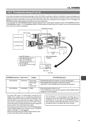
...errors. If so, set to "ENABLE". Use the side section's CH2 recording level control for recording, this recorded on another unit is open ? The GY-DV550 remains inoperative as long as on- • Time code data is shown only on page 8.) Sound and picture are not • Is the COUNTER ...sound input to "DISABLE". remedy the input sync signal. shown on the GY-DV550 don't work . • Is the VCR Setup Menu item No. 246 CH1 FRONT VR ENABLE set the switch to the GENLOCK IN connector disturbed? Battery alarm is displayed and the GYDV550 enters the non-operating mode even when...
...errors. If so, set to "ENABLE". Use the side section's CH2 recording level control for recording, this recorded on another unit is open ? The GY-DV550 remains inoperative as long as on- • Time code data is shown only on page 8.) Sound and picture are not • Is the COUNTER ...sound input to "DISABLE". remedy the input sync signal. shown on the GY-DV550 don't work . • Is the VCR Setup Menu item No. 246 CH1 FRONT VR ENABLE set the switch to the GENLOCK IN connector disturbed? Battery alarm is displayed and the GYDV550 enters the non-operating mode even when...


