Instruction Manual
Page 4
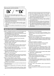
... use of tapes, we recommend not to record pictures within the first 2 to 3 minutes from 60.1 Hz to 2084.6 Hz. ● DV (i. This is a DV video system format camcorder. These instructions are for GY-DV5100U. Recording in color bar (SMPTE type) ● Superior operability with shooting conditions which varies as you for purchasing the DV Camcorder GY-DV5100. The playback sound can be monitored in recording or EE mode. Enables transfer of digital data...
... use of tapes, we recommend not to record pictures within the first 2 to 3 minutes from 60.1 Hz to 2084.6 Hz. ● DV (i. This is a DV video system format camcorder. These instructions are for GY-DV5100U. Recording in color bar (SMPTE type) ● Superior operability with shooting conditions which varies as you for purchasing the DV Camcorder GY-DV5100. The playback sound can be monitored in recording or EE mode. Enables transfer of digital data...

Instruction Manual
Page 5
... 9-1 Connecting a Video Component with DV Connector 65 10. INTRODUCTION 1-1 Precautions for Proper Use 6 1-2 Routine and Periodical Maintenance 7 1-3 Precautions for Recorded Scenes (Edit Search) ........ 56 7-3 If the Record-Standby Mode Continues 57 7-4 Checking Recorded Contents in Continuation of Head Cleaning Tape 7 1-4 Videocassette to be Used 8 1-6 Condensation 9 1-7 Characteristic CCD Phenomena 9 2. PREPARATIONS 5-1 Turning the Power ON 39 5-2 Cassette Loading and Unloading 40 5-3 Viewing the LCD Monitor 42 5-4 Setting, Displaying and Recording the Date and Time...
... 9-1 Connecting a Video Component with DV Connector 65 10. INTRODUCTION 1-1 Precautions for Proper Use 6 1-2 Routine and Periodical Maintenance 7 1-3 Precautions for Recorded Scenes (Edit Search) ........ 56 7-3 If the Record-Standby Mode Continues 57 7-4 Checking Recorded Contents in Continuation of Head Cleaning Tape 7 1-4 Videocassette to be Used 8 1-6 Condensation 9 1-7 Characteristic CCD Phenomena 9 2. PREPARATIONS 5-1 Turning the Power ON 39 5-2 Cassette Loading and Unloading 40 5-3 Viewing the LCD Monitor 42 5-4 Setting, Displaying and Recording the Date and Time...
Instruction Manual
Page 6
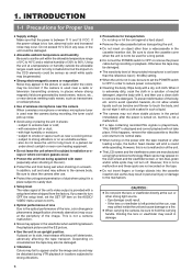
... LCD screen and the viewfinder screen are manufactured using it , and then use a clean cloth to remove the detergent. If placed on its normal state. ● When turning on the power with it in a place subject to sandy dust. ● Setup level The video signal of the unit's video output is not in locations subjected to 80%. Otherwise the tape may not turn OFF the setup level, set the POWER switch...
... LCD screen and the viewfinder screen are manufactured using it , and then use a clean cloth to remove the detergent. If placed on its normal state. ● When turning on the power with it in a place subject to sandy dust. ● Setup level The video signal of the unit's video output is not in locations subjected to 80%. Otherwise the tape may not turn OFF the setup level, set the POWER switch...
Instruction Manual
Page 7
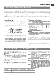
... GY-DV5100 incorporates precision mechanical parts, which will turn off after the tape has run as the indicator will collect dirt, wear out and deteriorate as a guide for Use of Head Cleaning Tape".) If head cleaning is displayed on the LCD monitor and in the picture or sound may appear in the viewfinder during outdoor use of Head Cleaning Tape Please use head cleaning tapes other than four times at high levels. Head Cleaning ● To maintain beautiful pictures...
... GY-DV5100 incorporates precision mechanical parts, which will turn off after the tape has run as the indicator will collect dirt, wear out and deteriorate as a guide for Use of Head Cleaning Tape".) If head cleaning is displayed on the LCD monitor and in the picture or sound may appear in the viewfinder during outdoor use of Head Cleaning Tape Please use head cleaning tapes other than four times at high levels. Head Cleaning ● To maintain beautiful pictures...
Instruction Manual
Page 10
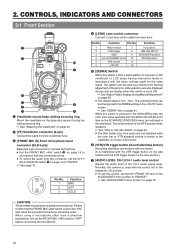
... 4 [LENS] Lens control connector Connect 12-pin lens control cable from the viewfinder here. 3 [FRONT MIC IN] Front microphone input connector (XLR 3-pin) Balanced 3-pin connector for the video signal. 2. Function Pin No. The luminance level can be changed with the menu settings made for camera microphone. ● Set the FRONT MIC +48V switch ! When using the sliding securing ring. ☞ See "Attaching the Viewfinder" on the ADVANCED PROCESS menu are also displayed during Manual Adjustment" on...
... 4 [LENS] Lens control connector Connect 12-pin lens control cable from the viewfinder here. 3 [FRONT MIC IN] Front microphone input connector (XLR 3-pin) Balanced 3-pin connector for the video signal. 2. Function Pin No. The luminance level can be changed with the menu settings made for camera microphone. ● Set the FRONT MIC +48V switch ! When using the sliding securing ring. ☞ See "Attaching the Viewfinder" on the ADVANCED PROCESS menu are also displayed during Manual Adjustment" on...
Instruction Manual
Page 16
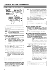
... V power supply (phantom microphone, etc.) is used to record with OFF cover open. The time code operates in a midway position. CH-2 : The CH-2 channel audio is -60 dBs. +48V : Set to this position when connected to move switches all the way. CAUTION: Make sure to audio equipment, etc. The reference input level is output. ☞ See "Outputting CH-3, CH-4 Channel Audio" on page 64. ☞ See "AUDIO/VIDEO Menu Screen" on the tape...
... V power supply (phantom microphone, etc.) is used to record with OFF cover open. The time code operates in a midway position. CH-2 : The CH-2 channel audio is -60 dBs. +48V : Set to this position when connected to move switches all the way. CAUTION: Make sure to audio equipment, etc. The reference input level is output. ☞ See "Outputting CH-3, CH-4 Channel Audio" on page 64. ☞ See "AUDIO/VIDEO Menu Screen" on the tape...
Instruction Manual
Page 17
VTR mode: The playback image is output. ● When the OUTPUT CHAR. MEMO: ● Alarm sound is not output. 4 Microphone attachment holes For attaching the microphone holder KA-A50U (optional) when the optional microphone MV-P615U or MV-P618U is used. ☞ See "Attaching the Microphone (optional)" on the CAMERA OPERATION menu screen is set to LETTER or SQUEEZE, 16:9 aspect ratio distinction ID signal is output in the VTR playback mode. MEMO: ●...
VTR mode: The playback image is output. ● When the OUTPUT CHAR. MEMO: ● Alarm sound is not output. 4 Microphone attachment holes For attaching the microphone holder KA-A50U (optional) when the optional microphone MV-P615U or MV-P618U is used. ☞ See "Attaching the Microphone (optional)" on the CAMERA OPERATION menu screen is set to LETTER or SQUEEZE, 16:9 aspect ratio distinction ID signal is output in the VTR playback mode. MEMO: ●...

Instruction Manual
Page 19
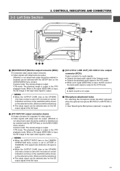
... be connected here. When a cable is selected with the Audio monitor volume control 1 on the rear section Connect external audio equipment or a microphone to the 7 DV connector. Set the MONITOR SELECT switch to the optional AA-P250 power adapter. DV: Connect a digital video component to the DV connector INT: Connect a DV Disk Recorder to the camera * Turn the camera off before using a stereotype jack and stereo sound should be output, the following setting should light and the lighting...
... be connected here. When a cable is selected with the Audio monitor volume control 1 on the rear section Connect external audio equipment or a microphone to the 7 DV connector. Set the MONITOR SELECT switch to the optional AA-P250 power adapter. DV: Connect a digital video component to the DV connector INT: Connect a DV Disk Recorder to the camera * Turn the camera off before using a stereotype jack and stereo sound should be output, the following setting should light and the lighting...
Instruction Manual
Page 24
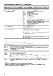
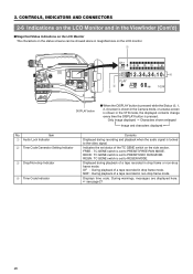
... the LCD/ VF (1/2) menu screen. ● Status 2 This screen displays the camera setup statuses. OPEN, F2, F2.8, F4, F5.6, F8, F11, F16, CLOSE It is not displayed when the lens is displayed. item on the Screen" 24 In the case of other DVCAM cassette than normal ■ : Iris set lower than normal Indicates the F-number of the connected lens. Indication FULL AUTO GAIN SHUTTER WHITE BAL IRIS LEVEL FILTER ZEBRA REMAIN AUDIO...
... the LCD/ VF (1/2) menu screen. ● Status 2 This screen displays the camera setup statuses. OPEN, F2, F2.8, F4, F5.6, F8, F11, F16, CLOSE It is not displayed when the lens is displayed. item on the Screen" 24 In the case of other DVCAM cassette than normal ■ : Iris set lower than normal Indicates the F-number of the connected lens. Indication FULL AUTO GAIN SHUTTER WHITE BAL IRIS LEVEL FILTER ZEBRA REMAIN AUDIO...
Instruction Manual
Page 26
... audio signal is set to the video signal. NDF : During playback of the TC GENE switch on the LCD monitor. 1 EDITSEARCH FILTER 1 3200K 2 5600K 1/8 ND .3 5600K .4 5600K 1/64 ND SHUTTER STATUS MONITOR MENU AUTO IRIS FULL AUTO BACK L NORMAL SPOT L BLACK LOLUX STRETCH NORMAL COMPRESS MODE VTR CAM POWER VTR ON OFF OPEN CH-1 AUDIO LEVEL CH-2 LCD BRIGHT FRONT REAR CH-1 CH-2 AUDIO IN AUDIO SELECT CH-1 CH-2 AUTO MANUAL DISPLAY PULL OPEN...
... audio signal is set to the video signal. NDF : During playback of the TC GENE switch on the LCD monitor. 1 EDITSEARCH FILTER 1 3200K 2 5600K 1/8 ND .3 5600K .4 5600K 1/64 ND SHUTTER STATUS MONITOR MENU AUTO IRIS FULL AUTO BACK L NORMAL SPOT L BLACK LOLUX STRETCH NORMAL COMPRESS MODE VTR CAM POWER VTR ON OFF OPEN CH-1 AUDIO LEVEL CH-2 LCD BRIGHT FRONT REAR CH-1 CH-2 AUDIO IN AUDIO SELECT CH-1 CH-2 AUTO MANUAL DISPLAY PULL OPEN...
Instruction Manual
Page 31
... CAM POWER VTR ON OFF OPEN CH-1 AUDIO LEVEL CH-2 LCD BRIGHT FRONT REAR CH-1 CH-2 AUDIO IN AUDIO SELECT CH-1 CH-2 AUTO MANUAL DISPLAY PULL OPEN GY-DV5100 STANDARD PACKAGE TRIPOD BASE FOCUS MANUAL UNIT *1 HZ-FM13 (FUJINON) HZ-FM15 (CANON) ZOOM SERVO UNIT HZ-ZS13B TRIPOD TP-P300 CARRYING CASE DOLLY TP-P205 ANTON BAUER ANTON BAUER BATTERY BATTERY HOLDER (PRO PAC, MAGNUM, (QR JVC DIGI) TRIMPAC, HYTRON) ANTON BAUER BATTERY CHARGER BATTERY...
... CAM POWER VTR ON OFF OPEN CH-1 AUDIO LEVEL CH-2 LCD BRIGHT FRONT REAR CH-1 CH-2 AUDIO IN AUDIO SELECT CH-1 CH-2 AUTO MANUAL DISPLAY PULL OPEN GY-DV5100 STANDARD PACKAGE TRIPOD BASE FOCUS MANUAL UNIT *1 HZ-FM13 (FUJINON) HZ-FM15 (CANON) ZOOM SERVO UNIT HZ-ZS13B TRIPOD TP-P300 CARRYING CASE DOLLY TP-P205 ANTON BAUER ANTON BAUER BATTERY BATTERY HOLDER (PRO PAC, MAGNUM, (QR JVC DIGI) TRIMPAC, HYTRON) ANTON BAUER BATTERY CHARGER BATTERY...
Instruction Manual
Page 38
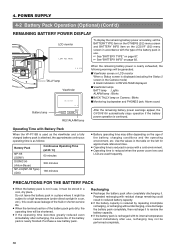
...-P115B is used frequently. Purchase a new battery pack. POWER SUPPLY 4-2 Battery Pack Operation (Optional) (Cont'd) REMAINING BATTERY POWER DISPLAY To display the remaining battery power accurately, set the LCD monitor BATTERY TYPE item on the OTHERS (2/2) menu screen and BATTERY INFO item on the age of the battery pack gets dirty, the operating time will be performed completely. 38 OPEN CH-1 AUDIO LEVEL CH-2 LCD BRIGHT FRONT REAR CH-1 CH-2 AUDIO INPUT AUDIO SELECT CH-1 CH-2 AUTO MANUAL DISPLAY PULL OPEN 10...
...-P115B is used frequently. Purchase a new battery pack. POWER SUPPLY 4-2 Battery Pack Operation (Optional) (Cont'd) REMAINING BATTERY POWER DISPLAY To display the remaining battery power accurately, set the LCD monitor BATTERY TYPE item on the OTHERS (2/2) menu screen and BATTERY INFO item on the age of the battery pack gets dirty, the operating time will be performed completely. 38 OPEN CH-1 AUDIO LEVEL CH-2 LCD BRIGHT FRONT REAR CH-1 CH-2 AUDIO INPUT AUDIO SELECT CH-1 CH-2 AUTO MANUAL DISPLAY PULL OPEN 10...
Instruction Manual
Page 43
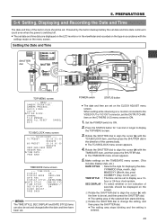
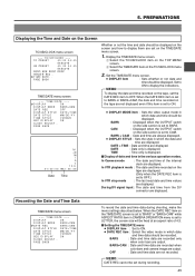
... L BLACK LOLUX STRETCH NORMAL COMPRESS MODE VTR CAM POWER VTR ON OFF OPEN CH-1 AUDIO LEVEL CH-2 LCD BRIGHT FRONT REAR CH-1 CH-2 AUDIO INPUT AUDIO SELECT CH-1 CH-2 AUTO MANUAL DISPLAY PULL OPEN TOP MENU screen --- TC/UB/CLOCK.. OTHERS.. PREPARATIONS 5-4 Setting, Displaying and Recording the Date and Time The date and time of the camera body. ● The TC/UB/CLOCK menu screen appears. 4. MENU --- TC/UB/CLOCK --- Rotate the SHUTTER dial to display the TOP MENU screen. 3. 5. TIME/DATE --- SEC DISPLAY : To...
... L BLACK LOLUX STRETCH NORMAL COMPRESS MODE VTR CAM POWER VTR ON OFF OPEN CH-1 AUDIO LEVEL CH-2 LCD BRIGHT FRONT REAR CH-1 CH-2 AUDIO INPUT AUDIO SELECT CH-1 CH-2 AUTO MANUAL DISPLAY PULL OPEN TOP MENU screen --- TC/UB/CLOCK.. OTHERS.. PREPARATIONS 5-4 Setting, Displaying and Recording the Date and Time The date and time of the camera body. ● The TC/UB/CLOCK menu screen appears. 4. MENU --- TC/UB/CLOCK --- Rotate the SHUTTER dial to display the TOP MENU screen. 3. 5. TIME/DATE --- SEC DISPLAY : To...
Instruction Manual
Page 45
... CAMERA OPERATION menu is set to ON. ● DATE REC item : Select the video mode in which the date and time are set to BARS. BARS : Date and time data are recorded only when color bars are displayed. MEMO: DATE REC cannot be set to LETTER, the screen size will be fixed at an aspect ratio of 4:3. ■ Setting the TIME/DATE menu ● DISPLAY item : Set to CAM. MEMO: To display the date and time recorded on the tape, set to BARS or BARS+CAM, the date...
... CAMERA OPERATION menu is set to ON. ● DATE REC item : Select the video mode in which the date and time are set to BARS. BARS : Date and time data are recorded only when color bars are displayed. MEMO: DATE REC cannot be set to LETTER, the screen size will be fixed at an aspect ratio of 4:3. ■ Setting the TIME/DATE menu ● DISPLAY item : Set to CAM. MEMO: To display the date and time recorded on the tape, set to BARS or BARS+CAM, the date...
Instruction Manual
Page 59
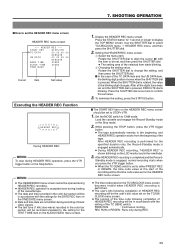
... user's bits following completion of HEADER REC recording will be recorded unrelated to confirm the set and the SHUTTER dial is accepted even during recording of the cassette tape. ● The date and time recorded in the color bar section will be the time code value set on the HEADER REC menu screen. ● The time code preset on the HEADER REC menu screen should be opened during HEADER REC recording. ● HEADER REC operation is pressed, EXECUTE starts blinking...
... user's bits following completion of HEADER REC recording will be recorded unrelated to confirm the set and the SHUTTER dial is accepted even during recording of the cassette tape. ● The date and time recorded in the color bar section will be the time code value set on the HEADER REC menu screen. ● The time code preset on the HEADER REC menu screen should be opened during HEADER REC recording. ● HEADER REC operation is pressed, EXECUTE starts blinking...
Instruction Manual
Page 65
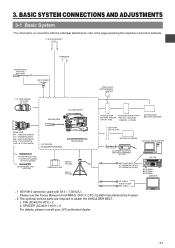
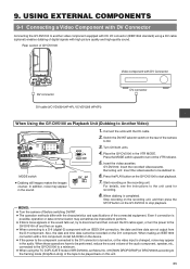
... to stop playback. Switch the DV/INT selector switch on the GY-DV5100 to be played back on , or the video input is turned on this unit. 65 EDITSEARCH FILTER 1 3200K 2 5600K 1/8 ND .3 5600K .4 5600K 1/64 ND SHUTTER STATUS MONITOR MENU AUTO IRIS FULL AUTO BACK L NORMAL SPOT L BLACK LOLUX STRETCH NORMAL COMPRESS MODE VTR CAM POWER VTR ON OFF OPEN CH-1 AUDIO LEVEL CH-2 LCD BRIGHT FRONT REAR CH-1 CH-2 AUDIO IN AUDIO...
... to stop playback. Switch the DV/INT selector switch on the GY-DV5100 to be played back on , or the video input is turned on this unit. 65 EDITSEARCH FILTER 1 3200K 2 5600K 1/8 ND .3 5600K .4 5600K 1/64 ND SHUTTER STATUS MONITOR MENU AUTO IRIS FULL AUTO BACK L NORMAL SPOT L BLACK LOLUX STRETCH NORMAL COMPRESS MODE VTR CAM POWER VTR ON OFF OPEN CH-1 AUDIO LEVEL CH-2 LCD BRIGHT FRONT REAR CH-1 CH-2 AUDIO IN AUDIO...
Instruction Manual
Page 66
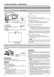
... 1/8 ND .3 5600K .4 5600K 1/64 ND SHUTTER STATUS MONITOR MENU AUTO IRIS FULL AUTO BACK L NORMAL SPOT L BLACK LOLUX STRETCH NORMAL COMPRESS MODE VTR CAM POWER VTR ON OFF OPEN CH-1 AUDIO LEVEL CH-2 LCD BRIGHT FRONT REAR CH-1 CH-2 AUDIO IN AUDIO SELECT CH-1 CH-2 AUTO MANUAL DISPLAY PULL OPEN MODE VTR CAM MODE switch Date and time data: Data transmitted from what they should be set to PLAY. USING EXTERNAL COMPONENTS 9-1 Connecting a Video Component with DV connector. Playback unit: Insert the recorded videocassette. 5.
... 1/8 ND .3 5600K .4 5600K 1/64 ND SHUTTER STATUS MONITOR MENU AUTO IRIS FULL AUTO BACK L NORMAL SPOT L BLACK LOLUX STRETCH NORMAL COMPRESS MODE VTR CAM POWER VTR ON OFF OPEN CH-1 AUDIO LEVEL CH-2 LCD BRIGHT FRONT REAR CH-1 CH-2 AUDIO IN AUDIO SELECT CH-1 CH-2 AUTO MANUAL DISPLAY PULL OPEN MODE VTR CAM MODE switch Date and time data: Data transmitted from what they should be set to PLAY. USING EXTERNAL COMPONENTS 9-1 Connecting a Video Component with DV connector. Playback unit: Insert the recorded videocassette. 5.
Instruction Manual
Page 90
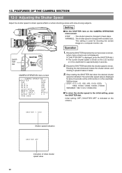
... L BLACK LOLUX STRETCH NORMAL COMPRESS MODE VTR CAM OPEN CH-1 AUDIO LEVEL CH-2 LCD BRIGHT FRONT REAR CH-1 CH-2 AUDIO IN AUDIO SELECT CH-1 CH-2 AUTO MANUAL DISPLAY PULL OPEN Setting ■ Set the SHUTTER item on the LCD monitor or in fixed steps. Rotate the SHUTTER dial while the normal screen is shown. (when menu screens are not displayed). (If "SHUTTER OFF" is displayed, press the SHUTTER dial.) ● The current shutter speed is changed with slow-moving subjects. Setting...
... L BLACK LOLUX STRETCH NORMAL COMPRESS MODE VTR CAM OPEN CH-1 AUDIO LEVEL CH-2 LCD BRIGHT FRONT REAR CH-1 CH-2 AUDIO IN AUDIO SELECT CH-1 CH-2 AUTO MANUAL DISPLAY PULL OPEN Setting ■ Set the SHUTTER item on the LCD monitor or in fixed steps. Rotate the SHUTTER dial while the normal screen is shown. (when menu screens are not displayed). (If "SHUTTER OFF" is displayed, press the SHUTTER dial.) ● The current shutter speed is changed with slow-moving subjects. Setting...

Instruction Manual
Page 96
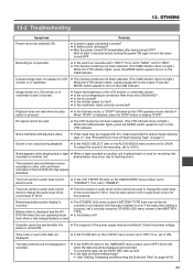
... replace displayed in the case of abnormalities during VCR operation, theTALLY lamps and viewfinder lamp will blink (or light steadily), and alarm sound will be input. MEMO: The GY-DV5100 is a microcomputer-controlled piece of the cassette is set to "REC". In this case, turn the power OFF, and then turn it ON again. 96 Also, when remaining tape or battery power becomes small, or in the shooting mode.) with the special head cleaning tape...
... replace displayed in the case of abnormalities during VCR operation, theTALLY lamps and viewfinder lamp will blink (or light steadily), and alarm sound will be input. MEMO: The GY-DV5100 is a microcomputer-controlled piece of the cassette is set to "REC". In this case, turn the power OFF, and then turn it ON again. 96 Also, when remaining tape or battery power becomes small, or in the shooting mode.) with the special head cleaning tape...
Instruction Manual
Page 99
...; Is the switch on the TIME/DATE menu screen set to CH1/2. Clean head with dirt. To output the sound of the LCD monitor or viewfinder screen. ● Is the color temperature conversion filter knob set to OFF? The front section's audio level control doesn't change the audio level of the sound input to CH-2. Remaining battery power display is dark or blurred. ● Adjust the brightness of the recording, set to display "STOP". Cassette cannot be ejected after being turned OFF? If...
...; Is the switch on the TIME/DATE menu screen set to CH1/2. Clean head with dirt. To output the sound of the LCD monitor or viewfinder screen. ● Is the color temperature conversion filter knob set to OFF? The front section's audio level control doesn't change the audio level of the sound input to CH-2. Remaining battery power display is dark or blurred. ● Adjust the brightness of the recording, set to display "STOP". Cassette cannot be ejected after being turned OFF? If...


