Instruction Manual
Page 1
Serial No. GVT0101-001B [J] and Serial No. Consists of CA-FSH35 and SP-UXH35 FS-H30- Retain this information for future reference. COMPACT COMPONENT SYSEM FS-H35- Consists of CA-FSH30 and SP-UXH30 COMPACT COMPONENT SYSTEM INSTRUCTIONS For Customer Use: Enter below the Model No. which are located either on the rear, bottom or side of the cabinet. Model No.
Serial No. GVT0101-001B [J] and Serial No. Consists of CA-FSH35 and SP-UXH35 FS-H30- Retain this information for future reference. COMPACT COMPONENT SYSEM FS-H35- Consists of CA-FSH30 and SP-UXH30 COMPACT COMPONENT SYSTEM INSTRUCTIONS For Customer Use: Enter below the Model No. which are located either on the rear, bottom or side of the cabinet. Model No.

Instruction Manual
Page 2
... radiate radio frequency energy and, if not installed and used in the literature accompanying the appliance. Increase the separation between the equipment and receiver. Connect the equipment into an outlet on standby, the STANDBY lamp lights red. • When the unit is encouraged to try to correct the interference by turning the equipment off ). G-1 However, there is connected. Do not remove screws...
... radiate radio frequency energy and, if not installed and used in the literature accompanying the appliance. Increase the separation between the equipment and receiver. Connect the equipment into an outlet on standby, the STANDBY lamp lights red. • When the unit is encouraged to try to correct the interference by turning the equipment off ). G-1 However, there is connected. Do not remove screws...
Instruction Manual
Page 4
... what is organized as follows: • The manual mainly explains operations using the buttons on pages 10 and 11. • The following cases: • After starting heating in a location with wet hands. DO NOT install the unit in a location near heat sources, or in the section "Common Operations" on the remote control. Power sources • When unplugging the unit from the wall...
... what is organized as follows: • The manual mainly explains operations using the buttons on pages 10 and 11. • The following cases: • After starting heating in a location with wet hands. DO NOT install the unit in a location near heat sources, or in the section "Common Operations" on the remote control. Power sources • When unplugging the unit from the wall...
Instruction Manual
Page 5
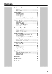
... Buttons 3 Main Unit 3 Remote Control 5 Getting Started 6 Supplied Accessories 6 Connecting Antennas 6 Connecting Speakers 7 Connecting Other Equipment 8 Putting the Batteries into the Remote Control 9 Common Operations 10 Setting the Clock 10 Turning On the Power 11 Adjusting the Volume 11 Adjusting the Tone (Bass/Treble 11 Reinforcing the Bass Sound 11 Listening to FM and AM Broadcasts 12 Tuning in to a Station 12 Presetting Stations 12 Tuning in to a Preset Station 13 Playing Back Discs 14 Playing Back the Entire Disc-Normal Play 14 Basic Disc Operations 15 Programming...
... Buttons 3 Main Unit 3 Remote Control 5 Getting Started 6 Supplied Accessories 6 Connecting Antennas 6 Connecting Speakers 7 Connecting Other Equipment 8 Putting the Batteries into the Remote Control 9 Common Operations 10 Setting the Clock 10 Turning On the Power 11 Adjusting the Volume 11 Adjusting the Tone (Bass/Treble 11 Reinforcing the Bass Sound 11 Listening to FM and AM Broadcasts 12 Tuning in to a Station 12 Presetting Stations 12 Tuning in to a Preset Station 13 Playing Back Discs 14 Playing Back the Entire Disc-Normal Play 14 Basic Disc Operations 15 Programming...

Instruction Manual
Page 6
Location of the Buttons Become familiar with the buttons on your unit. Main Unit Top view PHONES 1 2 3 4 5 6 Front view COMPACT DIGITAL AUDIO ONE TOUCH REC AUX TIMER/SNOOZE MULTI CONTROL 4 7 ¢ BAND TAPE TUNER CD AHB PRO VOLUME OPEN 7 8 9 p q w e STANDBY COMPACT COMPONENT SYSTEM r t 3
Location of the Buttons Become familiar with the buttons on your unit. Main Unit Top view PHONES 1 2 3 4 5 6 Front view COMPACT DIGITAL AUDIO ONE TOUCH REC AUX TIMER/SNOOZE MULTI CONTROL 4 7 ¢ BAND TAPE TUNER CD AHB PRO VOLUME OPEN 7 8 9 p q w e STANDBY COMPACT COMPONENT SYSTEM r t 3

Instruction Manual
Page 7
... unit 1 PHONES jack (11) 2 Disc cover 3 TIMER/SNOOZE button (10, 20 - 22) 4 ONE TOUCH REC (recording) button (18, 19) 5 (standby/on) button (11, 21) 6 Source buttons • AUX, @ # TAPE, BAND TUNER, and #/8 CD Pressing one of these buttons also turns on -time/off-time) indicators 5 CLOCK indicator 6 BASS indicator 7 SLEEP indicator 8 SNOOZE indicator 9 MONO and STEREO indicators p Main display • Shows the source name, frequency, etc. buttons (11) q Display window w STANDBY lamp (11) e Cassette holder r Remote sensor...
... unit 1 PHONES jack (11) 2 Disc cover 3 TIMER/SNOOZE button (10, 20 - 22) 4 ONE TOUCH REC (recording) button (18, 19) 5 (standby/on) button (11, 21) 6 Source buttons • AUX, @ # TAPE, BAND TUNER, and #/8 CD Pressing one of these buttons also turns on -time/off-time) indicators 5 CLOCK indicator 6 BASS indicator 7 SLEEP indicator 8 SNOOZE indicator 9 MONO and STEREO indicators p Main display • Shows the source name, frequency, etc. buttons (11) q Display window w STANDBY lamp (11) e Cassette holder r Remote sensor...

Instruction Manual
Page 8
... o VOLUME STANDBY COMPACT COMPONENT SYSTEM When using the remote control, point it at the remote sensor on the unit. 6 REV.MODE (reverse mode) button (17 - 19) 7 PRGM (program) button (15) 8 STANDBY/ON button (11, 21) 9 DISPLAY button (10) p CLOCK/TIMER button (10, 20, 21) q SLEEP button (22) w TREBLE button (11) e CANCEL button (16) r AUTO PRESET button (12) t FM MODE button (12) y REPEAT button (16) u RANDOM button (16) i AHB (Active Hyper Bass) PRO button (11) o VOLUME + / - Remote Control STANDBY/ON 1 2 3 8 4 5 6 DISPLAY 1 9 7 8 9 CLOCK /TIMER p 10 10 SLEEP q BASS...
... o VOLUME STANDBY COMPACT COMPONENT SYSTEM When using the remote control, point it at the remote sensor on the unit. 6 REV.MODE (reverse mode) button (17 - 19) 7 PRGM (program) button (15) 8 STANDBY/ON button (11, 21) 9 DISPLAY button (10) p CLOCK/TIMER button (10, 20, 21) q SLEEP button (22) w TREBLE button (11) e CANCEL button (16) r AUTO PRESET button (12) t FM MODE button (12) y REPEAT button (16) u RANDOM button (16) i AHB (Active Hyper Bass) PRO button (11) o VOLUME + / - Remote Control STANDBY/ON 1 2 3 8 4 5 6 DISPLAY 1 9 7 8 9 CLOCK /TIMER p 10 10 SLEEP q BASS...

Instruction Manual
Page 11
... IN connector (at home) or the DC IN connector (in any other connected equipment. Speaker grille To remove the speaker grille, insert your fingers at the same time for right audio signals. To connect the AC power cord AC power cord (supplied) AC IN Connect the AC power cord to plug in the unit and any equipment until all connections are for left audio signals, and red ones for safe and correct use...
... IN connector (at home) or the DC IN connector (in any other connected equipment. Speaker grille To remove the speaker grille, insert your fingers at the same time for right audio signals. To connect the AC power cord AC power cord (supplied) AC IN Connect the AC power cord to plug in the unit and any equipment until all connections are for left audio signals, and red ones for safe and correct use...
Instruction Manual
Page 12
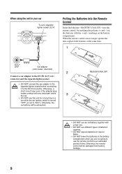
... switch is turned "OFF" (or set to the DC IN connector. When using the unit in your car To car's cigarette lighter socket (12 V) Putting the Batteries into the Remote Control Insert the batteries-R6(SUM-3)/AA(15F)-into the remote control, by matching the polarity (+ and -) on the battery compartment. Otherwise, a short-circuit may occur if the adapter plug makes contact with any metal part...
... switch is turned "OFF" (or set to the DC IN connector. When using the unit in your car To car's cigarette lighter socket (12 V) Putting the Batteries into the Remote Control Insert the batteries-R6(SUM-3)/AA(15F)-into the remote control, by matching the polarity (+ and -) on the battery compartment. Otherwise, a short-circuit may occur if the adapter plug makes contact with any metal part...

Instruction Manual
Page 13
... the (timer) indicator goes off . 2 Press CLOCK/TIMER (or TIMER/SNOOZE on the display. To change the clock 1 Make sure the (timer) indicator is not lit on the display. • If it is reset to adjust the hour, then press TIMER/SNOOZE. First time you press the button, the source indication and the clock time alternate on the unit) repeatedly until the unit enters the clock setting mode (the hour digits start over...
... the (timer) indicator goes off . 2 Press CLOCK/TIMER (or TIMER/SNOOZE on the display. To change the clock 1 Make sure the (timer) indicator is not lit on the display. • If it is reset to adjust the hour, then press TIMER/SNOOZE. First time you press the button, the source indication and the clock time alternate on the unit) repeatedly until the unit enters the clock setting mode (the hour digits start over...

Instruction Manual
Page 14
... standby. The volume level can damage your recording. • There is on the display. • Each time you finish, start playing any source next time. DO NOT turn on the unit, press STANDBY/ON STANDBY/ON (or on (AHB ON) and off . 11 On the remote control ONLY: 1 Press BASS to adjust the bass level or press TREBLE to an extremely high level; After setting the clock, the clock time...
... standby. The volume level can damage your recording. • There is on the display. • Each time you finish, start playing any source next time. DO NOT turn on the unit, press STANDBY/ON STANDBY/ON (or on (AHB ON) and off . 11 On the remote control ONLY: 1 Press BASS to adjust the bass level or press TREBLE to an extremely high level; After setting the clock, the clock time...
Instruction Manual
Page 16
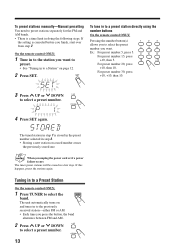
... remote control ONLY: 1 Press TUNER to select a preset number. To preset stations manually-Manual presetting You need to the previously received station-either FM or AM. • Each time you unplug the power cord or if a power failure occurs The tuner preset stations will be erased in a few days. When you press the button, the band alternates between FM and AM. 2 Press UP or DOWN UP to the station you finish, start...
... remote control ONLY: 1 Press TUNER to select a preset number. To preset stations manually-Manual presetting You need to the previously received station-either FM or AM. • Each time you unplug the power cord or if a power failure occurs The tuner preset stations will be erased in a few days. When you press the button, the band alternates between FM and AM. 2 Press UP or DOWN UP to the station you finish, start...
Instruction Manual
Page 20
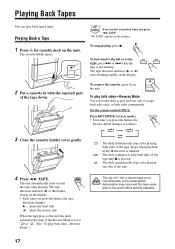
... the display. 2 Put a cassette in the pinch-rollers and the capstans. The cassette holder opens. To stop playing, press 7. The use of C-120 or thinner tape is not running. To play just one side of the tape. The tape direction indicator (3 or 2) starts flashing rapidly on the unit. On the remote control ONLY: Press REV.MODE (reverse mode). • Each time you press the button, the Reverse Mode changes...
... the display. 2 Put a cassette in the pinch-rollers and the capstans. The cassette holder opens. To stop playing, press 7. The use of C-120 or thinner tape is not running. To play just one side of the tape. The tape direction indicator (3 or 2) starts flashing rapidly on the unit. On the remote control ONLY: Press REV.MODE (reverse mode). • Each time you press the button, the Reverse Mode changes...
Instruction Manual
Page 21
... direction for the tape. • If the tape direction is not correct, press 2 3 TAPE twice then 7 to change the tape direction. • If you want to record on both sides-Reverse Mode On the remote control ONLY: Press REV.MODE (reverse mode) REV.MODE repeatedly until or is inserted when you can use type I tape for recording, lights up and start and end of a tape, see "Disc Direct Recording" on the display...
... direction for the tape. • If the tape direction is not correct, press 2 3 TAPE twice then 7 to change the tape direction. • If you want to record on both sides-Reverse Mode On the remote control ONLY: Press REV.MODE (reverse mode) REV.MODE repeatedly until or is inserted when you can use type I tape for recording, lights up and start and end of a tape, see "Disc Direct Recording" on the display...
Instruction Manual
Page 22
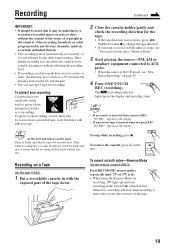
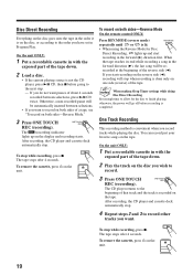
If you want to record other tracks you start recording in the forward (3) direction first. The tape stops after 4 seconds. recorded at the beginning of the tape down . 2 Load a disc. • If the current playing source is not the CD player, press 3/8 CD, then 7 before recording is lit. • When using the Reverse Mode for the disc to the next step. - After recording, the...
If you want to record other tracks you start recording in the forward (3) direction first. The tape stops after 4 seconds. recorded at the beginning of the tape down . 2 Load a disc. • If the current playing source is not the CD player, press 3/8 CD, then 7 before recording is lit. • When using the Reverse Mode for the disc to the next step. - After recording, the...
Instruction Manual
Page 23
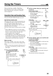
... lights up and the current on-time flashes on -time setting mode. How the timer actually works When the on-time comes, the unit automatically turns on (the [timer] indicator flashes just before turning off . • When the (timer) and the REC indicators are four timers available-Daily Timer, Recording Timer, Snooze Timer, and Sleep Timer. The timer setting remains in doing the following steps. When using the timers, you change it will be activated...
... lights up and the current on-time flashes on -time setting mode. How the timer actually works When the on-time comes, the unit automatically turns on (the [timer] indicator flashes just before turning off . • When the (timer) and the REC indicators are four timers available-Daily Timer, Recording Timer, Snooze Timer, and Sleep Timer. The timer setting remains in doing the following steps. When using the timers, you change it will be activated...
Instruction Manual
Page 24
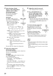
... deck. CD : plays a disc. (Daily Timer) • Load a disc. The unit enters the volume level setting mode. 5 Select the volume level. If you unplug the power cord or if a power failure occurs The timer will be used, first deactivate the timer. • If the unit is turned on when the timer on the display goes off the volume while the Recording Timer (REC TUNER) is in to the last station you were...
... deck. CD : plays a disc. (Daily Timer) • Load a disc. The unit enters the volume level setting mode. 5 Select the volume level. If you unplug the power cord or if a power failure occurs The timer will be used, first deactivate the timer. • If the unit is turned on when the timer on the display goes off the volume while the Recording Timer (REC TUNER) is in to the last station you were...
Instruction Manual
Page 25
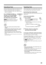
... the display. Using Sleep Timer With the Sleep Timer, you can fall asleep to set the clock first, then the timer again. On the remote control ONLY: 1 Press SLEEP. To change the shut-off the unit (standby) only for 5 minutes while the Daily Timer is in operation. • You can set the Sleep Timer when the unit is turned on when the Snooze Timer is working The Snooze Timer...
... the display. Using Sleep Timer With the Sleep Timer, you can fall asleep to set the clock first, then the timer again. On the remote control ONLY: 1 Press SLEEP. To change the shut-off the unit (standby) only for 5 minutes while the Daily Timer is in operation. • You can set the Sleep Timer when the unit is turned on when the Snooze Timer is working The Snooze Timer...
Instruction Manual
Page 28
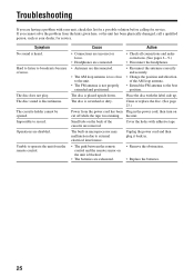
...; Remove the obstruction. • Replace the batteries. 25 Cause Action • Connections are incorrect or loose. • Headphones are connected. • Check all connections and make corrections. (See pages 6 - 9.) • Disconnect the headphones. • Antennas are disabled. Place the disc with the label side up. The disc does not play. Clean or replace the disc. (See page 23.) Power from the power cord has been Plug in...
...; Remove the obstruction. • Replace the batteries. 25 Cause Action • Connections are incorrect or loose. • Headphones are connected. • Check all connections and make corrections. (See pages 6 - 9.) • Disconnect the headphones. • Antennas are disabled. Place the disc with the label side up. The disc does not play. Clean or replace the disc. (See page 23.) Power from the power cord has been Plug in...
Instruction Manual
Page 30
Parts used for replacement are covered on a carry-in the Owner's Manual, normal maintenance, video and audio head cleaning; 4. Initial installation and installation and removal for the remainder of the Warranty Period. Operational adjustments covered in basis except for 90 days from the date of purchase); Accessories 8. JVC SHALL NOT BE LIABLE FOR THE LOSS OF USE OF THE PRODUCT, INCONVENIENCE, LOSS OR ANY OTHER DAMAGES...
Parts used for replacement are covered on a carry-in the Owner's Manual, normal maintenance, video and audio head cleaning; 4. Initial installation and installation and removal for the remainder of the Warranty Period. Operational adjustments covered in basis except for 90 days from the date of purchase); Accessories 8. JVC SHALL NOT BE LIABLE FOR THE LOSS OF USE OF THE PRODUCT, INCONVENIENCE, LOSS OR ANY OTHER DAMAGES...


