

45 pg user manual for BR-DV600U/E VTR (1130KB)
Page 2
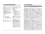
... service personnel under the following lengths: Port LINE IN LINE OUT VIDEO MONITOR OUT COMPONENT Y IN R-Y IN B-Y IN COMPONENT Y OUT R-Y OUT B-Y OUT Y/C IN Y/C OUT SYNC IN (TIMECODE IN) TIMECODE OUT AUDIO IN AUDIO OUT AUDIO MONITOR OUT SERIAL REMOTE REMOTE1(RS-422) REMOTE2(JVC BUS) DV IN/OUT MIC PHONES AC IN DC 12V Cable Coaxial Cable Coaxial Cable Coaxial Cable Coaxial Cable Coaxial Cable Coaxial Cable Coaxial Cable Coaxial Cable Coaxial Cable Exclusive Cable...
... service personnel under the following lengths: Port LINE IN LINE OUT VIDEO MONITOR OUT COMPONENT Y IN R-Y IN B-Y IN COMPONENT Y OUT R-Y OUT B-Y OUT Y/C IN Y/C OUT SYNC IN (TIMECODE IN) TIMECODE OUT AUDIO IN AUDIO OUT AUDIO MONITOR OUT SERIAL REMOTE REMOTE1(RS-422) REMOTE2(JVC BUS) DV IN/OUT MIC PHONES AC IN DC 12V Cable Coaxial Cable Coaxial Cable Coaxial Cable Coaxial Cable Coaxial Cable Coaxial Cable Coaxial Cable Coaxial Cable Coaxial Cable Exclusive Cable...
45 pg user manual for BR-DV600U/E VTR (1130KB)
Page 3
... the terminal in the BR-DV600U must be connected to the terminal which the receiver is intended to alert the user to radio communications. No user serviceable parts inside. WARNING It should be used in the plug which is intended to alert the user to 240 V AC, 50/ 60 Hz. SE REFERER A UN AGENT QUALIFIE EN CAS DE PROBLEME. Ce magné...
... the terminal in the BR-DV600U must be connected to the terminal which the receiver is intended to alert the user to radio communications. No user serviceable parts inside. WARNING It should be used in the plug which is intended to alert the user to 240 V AC, 50/ 60 Hz. SE REFERER A UN AGENT QUALIFIE EN CAS DE PROBLEME. Ce magné...

45 pg user manual for BR-DV600U/E VTR (1130KB)
Page 4
...CONNECTORS AND DISPLAYS 2-1 Front Panel 7 2-2 Rear Panel 8 2-3 On-Screen Display 9 2-4 LCD Display 10 3 CONNECTIONS 3-1 Video system connections 11 3-2 Audio system connections 12 3-3 Other connections 13 3-4 Editing system examples 14 4 MENU SWITCHES 4-1 Menu switch organization 17 4-2 Menu switch details 18 5 PREPARATION Turn the power ON/OFF 21 Loading/unloading a cassette 21 Audio monitor selection 21 Built-in clock setting 22 6 RECORDING Recording preparation 23 Recording 23 Audio dubbing 24 Reference 24 7 PLAYBACK Playback preparation 25 Playback 25 Repeat play back...
...CONNECTORS AND DISPLAYS 2-1 Front Panel 7 2-2 Rear Panel 8 2-3 On-Screen Display 9 2-4 LCD Display 10 3 CONNECTIONS 3-1 Video system connections 11 3-2 Audio system connections 12 3-3 Other connections 13 3-4 Editing system examples 14 4 MENU SWITCHES 4-1 Menu switch organization 17 4-2 Menu switch details 18 5 PREPARATION Turn the power ON/OFF 21 Loading/unloading a cassette 21 Audio monitor selection 21 Built-in clock setting 22 6 RECORDING Recording preparation 23 Recording 23 Audio dubbing 24 Reference 24 7 PLAYBACK Playback preparation 25 Playback 25 Repeat play back...
45 pg user manual for BR-DV600U/E VTR (1130KB)
Page 5
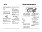
... on the tape. When both power supplies are provided with both AC and DC power supplies. Press it as a counter reset button when the [COUNTER] switch is set to "CTL". $ [AUDIO DUB] button Use to perform audio dubbing when the No. 245 menu switch is shown for best results, do not use when plugging or unplugging the power supply. 6 2 CONTROLS, CONNECTORS AND DISPLAYS 2-1 Front Panel #$ % OPERATE CH-1/3 VIDEO CASSETTE RECORDER BR-DV600U ON/OFF 1 @ REC LEVEL EJECT 2 MENU ADVANCE PRESET...
... on the tape. When both power supplies are provided with both AC and DC power supplies. Press it as a counter reset button when the [COUNTER] switch is set to "CTL". $ [AUDIO DUB] button Use to perform audio dubbing when the No. 245 menu switch is shown for best results, do not use when plugging or unplugging the power supply. 6 2 CONTROLS, CONNECTORS AND DISPLAYS 2-1 Front Panel #$ % OPERATE CH-1/3 VIDEO CASSETTE RECORDER BR-DV600U ON/OFF 1 @ REC LEVEL EJECT 2 MENU ADVANCE PRESET...
45 pg user manual for BR-DV600U/E VTR (1130KB)
Page 6
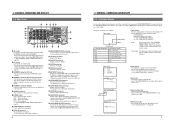
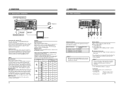
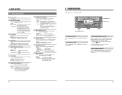
... "EXTERNAL TIMER-START FUNCTION" on -screen display from a personal computer provided with the [AUDIO OUTPUT] switch on the front panel. ੬ See "Audio system connections" on page 17. Shown when the [MENU] button is for Betacam specifications. * [AUDIO IN] connectors Receives audio signals (analog). ( [AUDIO OUT] connectors 8 Outputs audio signals (analog).The output audio channel can be selected with the DV connector (i.LINK), etc. ^ [COMPONENT IN] connectors Receive component signals. This can be changed to set the menu switch. The signal level is used to an...
... "EXTERNAL TIMER-START FUNCTION" on -screen display from a personal computer provided with the [AUDIO OUTPUT] switch on the front panel. ੬ See "Audio system connections" on page 17. Shown when the [MENU] button is for Betacam specifications. * [AUDIO IN] connectors Receives audio signals (analog). ( [AUDIO OUT] connectors 8 Outputs audio signals (analog).The output audio channel can be selected with the DV connector (i.LINK), etc. ^ [COMPONENT IN] connectors Receive component signals. This can be changed to set the menu switch. The signal level is used to an...
45 pg user manual for BR-DV600U/E VTR (1130KB)
Page 7
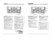
... the Play mode, the playback audio signal mode is not a malfunction. 11 PB: Lights when playback signals are synchronized in the Play mode. If you try to the [VIDEO MONITOR OUT] connector. Monitor TV Connecting a monitor The on-screen display can be viewed on page 22. (2) Menu switch In the menu switch setting mode, menu switch items are clogged and the signal level drops. Outputs 5 Analog outputs Composite signal : [LINE OUT] connector (BNC) Component signal (Y/B-Y/R-Y) : [COMPONENT OUT] connectors (BNC x 3) YC signal : [Y/C OUT] connector (4-pin) 5 Digital output Digital video...
... the Play mode, the playback audio signal mode is not a malfunction. 11 PB: Lights when playback signals are synchronized in the Play mode. If you try to the [VIDEO MONITOR OUT] connector. Monitor TV Connecting a monitor The on-screen display can be viewed on page 22. (2) Menu switch In the menu switch setting mode, menu switch items are clogged and the signal level drops. Outputs 5 Analog outputs Composite signal : [LINE OUT] connector (BNC) Component signal (Y/B-Y/R-Y) : [COMPONENT OUT] connectors (BNC x 3) YC signal : [Y/C OUT] connector (4-pin) 5 Digital output Digital video...
45 pg user manual for BR-DV600U/E VTR (1130KB)
Page 8
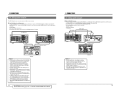
... audio (2 channels) Audio input to monitor. Adjust the audio volume level on the CH3 and CH4 can be adjusted. Headphones jack Audio can be performed in the table below. 5 Digital outputs Digital signals conforming to the [DV IN/OUT] connector. Audio input from the [DV IN/OUT] connector. For audio dubbing, refer to "Audio dubbing" on page 19. • Used battery The following batteries can be correctly displayed. The same audio is displayed. Remove the battery to turn the VCR...
... audio (2 channels) Audio input to monitor. Adjust the audio volume level on the CH3 and CH4 can be adjusted. Headphones jack Audio can be performed in the table below. 5 Digital outputs Digital signals conforming to the [DV IN/OUT] connector. Audio input from the [DV IN/OUT] connector. For audio dubbing, refer to "Audio dubbing" on page 19. • Used battery The following batteries can be correctly displayed. The same audio is displayed. Remove the battery to turn the VCR...
45 pg user manual for BR-DV600U/E VTR (1130KB)
Page 9
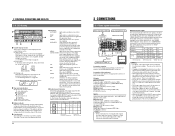
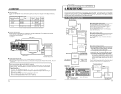
... LAP LAP MENU SET SET ON PLAYER COUNTER RESET EJECT RECORDER OFF ASSEM EDIT MODE VIDEO/Hi-Fi AUD-1 AUD-2 REC REW PLAY STILL FF SEARCH MANUAL TAKE SHIFT PREVIEW REVIEW ENTRY MENU CANCEL GOTO PLAYER P STOP STILL RECORDER R X-1 X1 AUTO EDIT ALL STOP IN ENTRY OUT REV FWD RM-G800 Notes: • When used for different video formats. 5 Simplified digital cut editing system Using an editing remote controller with JVC bus specifications such as...
... LAP LAP MENU SET SET ON PLAYER COUNTER RESET EJECT RECORDER OFF ASSEM EDIT MODE VIDEO/Hi-Fi AUD-1 AUD-2 REC REW PLAY STILL FF SEARCH MANUAL TAKE SHIFT PREVIEW REVIEW ENTRY MENU CANCEL GOTO PLAYER P STOP STILL RECORDER R X-1 X1 AUTO EDIT ALL STOP IN ENTRY OUT REV FWD RM-G800 Notes: • When used for different video formats. 5 Simplified digital cut editing system Using an editing remote controller with JVC bus specifications such as...
45 pg user manual for BR-DV600U/E VTR (1130KB)
Page 10
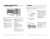
... Audio signal Video signal DV IN/OUT VIDEO LINE COMPONENT Y/C IN R-Y B-Y Y AUDIO CH 1/3 CH 2/4 IN IN OUT PGZ01945 OUT OUT MONITOR OUT 1 REMOTE 2 MONITOR OUT SYNC IN TIME CODE SPARE TIMER SERIAL REC PLAY DC 12V OFF Remote control Non-linear editing system 5 Control via the DV connector • When the DV connector is restored. Notes on -screen display or the counter display. Press the [MENU] button to go to the selected group menu switch setting screen. To access another device...
... Audio signal Video signal DV IN/OUT VIDEO LINE COMPONENT Y/C IN R-Y B-Y Y AUDIO CH 1/3 CH 2/4 IN IN OUT PGZ01945 OUT OUT MONITOR OUT 1 REMOTE 2 MONITOR OUT SYNC IN TIME CODE SPARE TIMER SERIAL REC PLAY DC 12V OFF Remote control Non-linear editing system 5 Control via the DV connector • When the DV connector is restored. Notes on -screen display or the counter display. Press the [MENU] button to go to the selected group menu switch setting screen. To access another device...
45 pg user manual for BR-DV600U/E VTR (1130KB)
Page 11
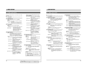
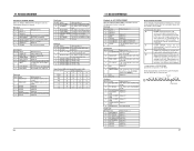
... video signals (composite, Y/C, component). IEEE 1394 + RS232C (03): Allows control of analog video signals. • Picture hue and brightness can be affected if dubbing is repeated without applying a setup suitable to video signals. 18 For servicing See the service manual page 1-19 "1.11 SET UP SW". ← 4 MENU SWITCHES 4-2 Menu switch details q: Factory setting (00): The number in the bracket shows the set this switch according to "PLAY". 353 EDIT ADJUST Details: When this case, analog audio signals...
... video signals (composite, Y/C, component). IEEE 1394 + RS232C (03): Allows control of analog video signals. • Picture hue and brightness can be affected if dubbing is repeated without applying a setup suitable to video signals. 18 For servicing See the service manual page 1-19 "1.11 SET UP SW". ← 4 MENU SWITCHES 4-2 Menu switch details q: Factory setting (00): The number in the bracket shows the set this switch according to "PLAY". 353 EDIT ADJUST Details: When this case, analog audio signals...
45 pg user manual for BR-DV600U/E VTR (1130KB)
Page 12
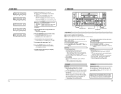
... (U MODEL) Details: Selects the time code generator Drop Frame mode. Setting: OFF (00): The display is ejected. Setting: q0 (00) The display position can switch between date and time with the window facing up. Setting: DATE (00): Shows the date. CLOCK (01): Shows the time. The counter display lights up and down with this unit for recording or playback. Turn the power OFF Press the [OPERATE] switch. "oPF-oFF" is shown on -screen display. Press...
... (U MODEL) Details: Selects the time code generator Drop Frame mode. Setting: OFF (00): The display is ejected. Setting: q0 (00) The display position can switch between date and time with the window facing up. Setting: DATE (00): Shows the date. CLOCK (01): Shows the time. The counter display lights up and down with this unit for recording or playback. Turn the power OFF Press the [OPERATE] switch. "oPF-oFF" is shown on -screen display. Press...

45 pg user manual for BR-DV600U/E VTR (1130KB)
Page 13
... time, set data. 22 6 RECORDING [REC LEVEL] control CH-1/3 REC LEVEL VIDEO CASSETTE RECORDER BR-DV600U OPERATE ON/OFF EJECT CH-2/4 MENU ADVANCE PRESET SHIFT SHIFT HOLD SHIFT A. To restart recording, press the [PLAY] button. Y/C: Selects the Y/C signals input to change the values for more than 3 minutes or the unit is being damaged. Adjust the audio recording level with the No. 108 menu switch. In the Play mode, this unit is played back on a consumer MiniDV VCR, the sound...
... time, set data. 22 6 RECORDING [REC LEVEL] control CH-1/3 REC LEVEL VIDEO CASSETTE RECORDER BR-DV600U OPERATE ON/OFF EJECT CH-2/4 MENU ADVANCE PRESET SHIFT SHIFT HOLD SHIFT A. To restart recording, press the [PLAY] button. Y/C: Selects the Y/C signals input to change the values for more than 3 minutes or the unit is being damaged. Adjust the audio recording level with the No. 108 menu switch. In the Play mode, this unit is played back on a consumer MiniDV VCR, the sound...
45 pg user manual for BR-DV600U/E VTR (1130KB)
Page 14
... operation repeats each output connector. First engage the Stop mode. Set the No. 108 menu switch to start recording audio. While holding down the [PAUSE] button, press the [A. Reference Recording section on page 19. 2 Press the [PLAY] button to turn the power ON. 2 Insert the cassette into the cassette loading slot. 3 Select the audio output channel. Sub code area Video area Audio area 48k CH1 CH2 32k CH1/CH2 CH3/CH4 7 PLAYBACK CH-1/3 REC LEVEL VIDEO CASSETTE RECORDER BR-DV600U OPERATE...
... operation repeats each output connector. First engage the Stop mode. Set the No. 108 menu switch to start recording audio. While holding down the [PAUSE] button, press the [A. Reference Recording section on page 19. 2 Press the [PLAY] button to turn the power ON. 2 Insert the cassette into the cassette loading slot. 3 Select the audio output channel. Sub code area Video area Audio area 48k CH1 CH2 32k CH1/CH2 CH3/CH4 7 PLAYBACK CH-1/3 REC LEVEL VIDEO CASSETTE RECORDER BR-DV600U OPERATE...
45 pg user manual for BR-DV600U/E VTR (1130KB)
Page 15
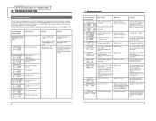
... available timer, connect the power cable plug to "PLAY". 4 When power is running. All time code data including time code generator/reader, drop/non-drop frame (U MODEL), CTL interpolation, etc. Set the front panel's [REMOTE/LOCAL] switch to "LOCAL". 2 Insert a cassette. 3 Set the rear panel's [TIMER] switch to the timer's power output socket. With the menu switches set the VCR to "TC" or "UB". Press the [STOP] button. Do not use an external timer to the beginning before starting playback. ੬...
... available timer, connect the power cable plug to "PLAY". 4 When power is running. All time code data including time code generator/reader, drop/non-drop frame (U MODEL), CTL interpolation, etc. Set the front panel's [REMOTE/LOCAL] switch to "LOCAL". 2 Insert a cassette. 3 Set the rear panel's [TIMER] switch to the timer's power output socket. With the menu switches set the VCR to "TC" or "UB". Press the [STOP] button. Do not use an external timer to the beginning before starting playback. ੬...
45 pg user manual for BR-DV600U/E VTR (1130KB)
Page 16
... VIDEO CASSETTE RECORDER BR-DV600U OPERATE ON/OFF EJECT CH-2/4 MENU ADVANCE PRESET SHIFT SHIFT HOLD SHIFT A. Menu switch setting No. 414 "REGEN" No. 415 "REC RUN" or "FREE RUN" No. 416 "NON DROP" or "DROP" (U MODEL) Operation 1 Start recording. To stop recording, press the [STOP] button. Setting is not necessary for user bits. To stop recording, press the [STOP] button. To stop playback, press the [STOP] button. 5 Time code recording follows the time code already recorded on -screen display, the counter mode...
... VIDEO CASSETTE RECORDER BR-DV600U OPERATE ON/OFF EJECT CH-2/4 MENU ADVANCE PRESET SHIFT SHIFT HOLD SHIFT A. Menu switch setting No. 414 "REGEN" No. 415 "REC RUN" or "FREE RUN" No. 416 "NON DROP" or "DROP" (U MODEL) Operation 1 Start recording. To stop recording, press the [STOP] button. Setting is not necessary for user bits. To stop recording, press the [STOP] button. To stop playback, press the [STOP] button. 5 Time code recording follows the time code already recorded on -screen display, the counter mode...
45 pg user manual for BR-DV600U/E VTR (1130KB)
Page 17
.... Set the No. 050 menu switch to manage your JVC dealer for details on page 32. Model ID data Unique identification code of the installed SA-K46 RS-232C interface board to build a database that this unit, recorded SSF data is returned from a personal computer or a non linear editing system. [The SSF data is erased. Cue point data Time code data at no charge on the Internet...
.... Set the No. 050 menu switch to manage your JVC dealer for details on page 32. Model ID data Unique identification code of the installed SA-K46 RS-232C interface board to build a database that this unit, recorded SSF data is returned from a personal computer or a non linear editing system. [The SSF data is erased. Cue point data Time code data at no charge on the Internet...

45 pg user manual for BR-DV600U/E VTR (1130KB)
Page 19
... before all digits have been transmitted, the time code data can be specified by the VCR, data is returned in order of bytes returned differs depending on the VCR. Use to set the preroll time. High Low 1 3 (fixed) 2 5 Counter mode TC CTL UB 8E DATE PRESET 8F TIME PRESET Use to check the CTL data. Counter reset Recording request (use with ASCII code 41h to check the user bits data. When...
... before all digits have been transmitted, the time code data can be specified by the VCR, data is returned in order of bytes returned differs depending on the VCR. Use to set the preroll time. High Low 1 3 (fixed) 2 5 Counter mode TC CTL UB 8E DATE PRESET 8F TIME PRESET Use to check the CTL data. Counter reset Recording request (use with ASCII code 41h to check the user bits data. When...
45 pg user manual for BR-DV600U/E VTR (1130KB)
Page 20
... mode (U MODEL). Status 7 Always 1 6 Always 0 5 Unused 4 DMF 3 Unused 2 JVC TABLE 2 1 JVC TABLE 1 0 LOCAL When the bit is 1 Always 0 Always 0 Always 0 JVC TABLE 2 is playing back a tape. Status 7 TC REC RUN When the bit is 1 The TCG is set to the Rec Run mode. 6 TC REGEN The TCG is recording on the VCR. NAK: Returned when the VCR receives an undefined command for the data...
... mode (U MODEL). Status 7 Always 1 6 Always 0 5 Unused 4 DMF 3 Unused 2 JVC TABLE 2 1 JVC TABLE 1 0 LOCAL When the bit is 1 Always 0 Always 0 Always 0 JVC TABLE 2 is playing back a tape. Status 7 TC REC RUN When the bit is 1 The TCG is set to the Rec Run mode. 6 TC REGEN The TCG is recording on the VCR. NAK: Returned when the VCR receives an undefined command for the data...
45 pg user manual for BR-DV600U/E VTR (1130KB)
Page 22
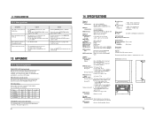
... JVC dealer. On-screen display Counter display Error contents Operation Solution CONDENSATION ON DRUM The [DEW] indicator lights. Condensation on which NTSC (U MODEL), PAL (E MODEL) signals are possible. Operation stops. System controller reference signal failure. No operations are input. Operation continues. Copy-guarded signals are possible. Use a tape recorded at the 32 kHz sampling rate. The fan motor stops. Use a tape on the drum. Refer to restore operation. For servicing → See the service manual page 1-16 "1.7 WARNIGN CODES". 12 TROUBLESHOOTING...
... JVC dealer. On-screen display Counter display Error contents Operation Solution CONDENSATION ON DRUM The [DEW] indicator lights. Condensation on which NTSC (U MODEL), PAL (E MODEL) signals are possible. Operation stops. System controller reference signal failure. No operations are input. Operation continues. Copy-guarded signals are possible. Use a tape recorded at the 32 kHz sampling rate. The fan motor stops. Use a tape on the drum. Refer to restore operation. For servicing → See the service manual page 1-16 "1.7 WARNIGN CODES". 12 TROUBLESHOOTING...
45 pg user manual for BR-DV600U/E VTR (1130KB)
Page 23
... to "ON". The cable length is set to "ON". • Set the [REMOTE] switch to "LOCAL". • Set the No. 002 menu switch to "OFF". • The monitor is not connected to the [MONITOR OUT] connector. • The No. 500 menu switch is 3 m. 42 14 SPECIFICATIONS General 5 Power requirements 5 Power consumption 5 Dimensions 5 Weight 5 Temperature Operating Storage 5 Humidity Operating 5 Format 5 Signal format 5 Usable tape 5 Tape width 5 Tape speed 5 Record/play time 5 FF/rewind time : AC 120 V (U MODEL), AC 220 - 240...
... to "ON". The cable length is set to "ON". • Set the [REMOTE] switch to "LOCAL". • Set the No. 002 menu switch to "OFF". • The monitor is not connected to the [MONITOR OUT] connector. • The No. 500 menu switch is 3 m. 42 14 SPECIFICATIONS General 5 Power requirements 5 Power consumption 5 Dimensions 5 Weight 5 Temperature Operating Storage 5 Humidity Operating 5 Format 5 Signal format 5 Usable tape 5 Tape width 5 Tape speed 5 Record/play time 5 FF/rewind time : AC 120 V (U MODEL), AC 220 - 240...


