Product Guide
Page 4
... Replaceable Units and Sensor Data Records 48 System Event Log ...48 Platform Event Management 48 Emergency Management Port 49 Intel Server Management ...49 Using the System Setup Utility 50 Creating SSU Diskettes 50 Running the SSU...51 Setting Boot Device Priority 52 Setting Passwords and Security Options 52 Viewing the System Event Log 54 Viewing FRU Information 54 Viewing Sensor Data Records 55 Updating System Firmware and BIOS 55 Saving and Restoring...
... Replaceable Units and Sensor Data Records 48 System Event Log ...48 Platform Event Management 48 Emergency Management Port 49 Intel Server Management ...49 Using the System Setup Utility 50 Creating SSU Diskettes 50 Running the SSU...51 Setting Boot Device Priority 52 Setting Passwords and Security Options 52 Viewing the System Event Log 54 Viewing FRU Information 54 Viewing Sensor Data Records 55 Updating System Firmware and BIOS 55 Saving and Restoring...

Product Guide
Page 6
... Summary...129 Chassis Access ...130 Main Chassis Components 131 Electronics Bay Components 132 Front Control Panel ...133 Rear Panel ...134 Peripheral Device Bay ...135 Hot-Swap Hard Drive Bays 135 Power Supplies ...136 System Cooling ...136 Server Board Set Features 137 Baseboard Connector and Component Locations 138 Baseboard Jumpers...139 Processors ...141 DIMM Memory ...141 Onboard Video ...141 SCSI Controller...141 Network Interface Controllers 142 Network Teaming Features 143 ACPI ...145 vi Intel SPSH4 Server Platform Product Guide
... Summary...129 Chassis Access ...130 Main Chassis Components 131 Electronics Bay Components 132 Front Control Panel ...133 Rear Panel ...134 Peripheral Device Bay ...135 Hot-Swap Hard Drive Bays 135 Power Supplies ...136 System Cooling ...136 Server Board Set Features 137 Baseboard Connector and Component Locations 138 Baseboard Jumpers...139 Processors ...141 DIMM Memory ...141 Onboard Video ...141 SCSI Controller...141 Network Interface Controllers 142 Network Teaming Features 143 ACPI ...145 vi Intel SPSH4 Server Platform Product Guide

Product Guide
Page 8
.... Removing a Power Distribution Board 117 49. Removing a Fan Distribution Board 118 50. SPSH4 Server Hot-Swap Access 130 53. Electronics Bay Internal Components 132 55. SPSH4 Front Control Panel 133 56. Baseboard Connector and Component Locations 138 59. Baseboard Jumpers 139 Tables 1. SPSH4 Server Physical Specifications 30 3. Software Security Features 36 5. BIOS Setup Menu Navigation 40 6. Command Line Format 63 7. LED States for Hot-Plug PCI Add-In Boards 94 30. LED Power Supply Status Indicators 90 9. Feature Summary...129 11. Server Board Set...
.... Removing a Power Distribution Board 117 49. Removing a Fan Distribution Board 118 50. SPSH4 Server Hot-Swap Access 130 53. Electronics Bay Internal Components 132 55. SPSH4 Front Control Panel 133 56. Baseboard Connector and Component Locations 138 59. Baseboard Jumpers 139 Tables 1. SPSH4 Server Physical Specifications 30 3. Software Security Features 36 5. BIOS Setup Menu Navigation 40 6. Command Line Format 63 7. LED States for Hot-Plug PCI Add-In Boards 94 30. LED Power Supply Status Indicators 90 9. Feature Summary...129 11. Server Board Set...
Product Guide
Page 16
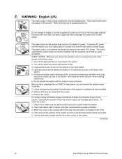
... chassis with the screws removed earlier, and tighten them firmly. 4. The socket outlet that cables, add-in this product contains no user-serviceable parts. continued 16 Intel SPSH4 Server Platform Product Guide The power cord(s) is not the exact type required. After you must unplug each supply. Attach the covers to prevent unauthorized access inside the system. 2. A product with the chassis covers removed. Operating the system without the covers in this : 1.
... chassis with the screws removed earlier, and tighten them firmly. 4. The socket outlet that cables, add-in this product contains no user-serviceable parts. continued 16 Intel SPSH4 Server Platform Product Guide The power cord(s) is not the exact type required. After you must unplug each supply. Attach the covers to prevent unauthorized access inside the system. 2. A product with the chassis covers removed. Operating the system without the covers in this : 1.

Product Guide
Page 32
... of memory installed and the number of the screen. Plug the video monitor power cord into the CD-ROM drive. Shortly after the splash screen is disabled in Table 3 on page 33, or you must press specific keys at the bottom of option boards installed. 8. If you enter BIOS Setup, the Service Partition, or the Adaptec† SCSISelect† Utility, when you plug it . 3. Connecting the Monitor, Keyboard, and Mouse Connect the monitor, keyboard, and mouse to the appropriate connectors on the rear panel of...
... of memory installed and the number of the screen. Plug the video monitor power cord into the CD-ROM drive. Shortly after the splash screen is disabled in Table 3 on page 33, or you must press specific keys at the bottom of option boards installed. 8. If you enter BIOS Setup, the Service Partition, or the Adaptec† SCSISelect† Utility, when you plug it . 3. Connecting the Monitor, Keyboard, and Mouse Connect the monitor, keyboard, and mouse to the appropriate connectors on the rear panel of...

Product Guide
Page 33
... physical configuration of processors, fans, or power supplies, you use during POST and display a menu for * Note: Using BIOS Setup, you can use the displayed menu to change the boot device, the change the number of the server, false errors might be generated by sensors that don't actually exist, and sensors that is displayed. (The system pauses after displaying an error.) Enter BIOS Setup during POST. Time Diagnostic Screen, in which case POST does not display the splash screen. Enter the Adaptec SCSISelect Utility...
... physical configuration of processors, fans, or power supplies, you use during POST and display a menu for * Note: Using BIOS Setup, you can use the displayed menu to change the boot device, the change the number of the server, false errors might be generated by sensors that don't actually exist, and sensors that is displayed. (The system pauses after displaying an error.) Enter BIOS Setup during POST. Time Diagnostic Screen, in which case POST does not display the splash screen. Enter the Adaptec SCSISelect Utility...

Product Guide
Page 34
... run your server and applications, you must install the operating system of available items, select Create Service Partition-first time. 5. From the menu, select Utilities and press the key. 3. Remove the System Resource CD from the CD-ROM drive and exit from the CD-ROM. 6. Follow the installation instructions that came with Intel® Server Management (ISM) software, provides emergency remote management and remote server setup. The CD contains documentation, device drivers, utilities, Intel Server Management, and other useful information and software...
... run your server and applications, you must install the operating system of available items, select Create Service Partition-first time. 5. From the menu, select Utilities and press the key. 3. Remove the System Resource CD from the CD-ROM drive and exit from the CD-ROM. 6. Follow the installation instructions that came with Intel® Server Management (ISM) software, provides emergency remote management and remote server setup. The CD contains documentation, device drivers, utilities, Intel Server Management, and other useful information and software...

Product Guide
Page 36
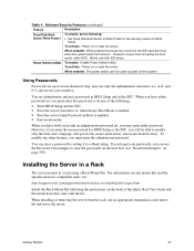
... video is blanked, if enabled. • Diskette drive is write protected, if enabled. • Power, Sleep, and Reset buttons on Boot To enable, do all of the features can enable these features using the System Setup Utility (SSU) (page 50). Password on the front panel are disabled. • Mouse and keyboard input are ignored, except for secure mode. To activate: Power on or reset the server. Most of the following : • Set a user password. • Enable Secure Mode Boot...
... video is blanked, if enabled. • Diskette drive is write protected, if enabled. • Power, Sleep, and Reset buttons on Boot To enable, do all of the features can enable these features using the System Setup Utility (SSU) (page 50). Password on the front panel are disabled. • Mouse and keyboard input are ignored, except for secure mode. To activate: Power on or reset the server. Most of the following : • Set a user password. • Enable Secure Mode Boot...
Product Guide
Page 37
... mode hot-key. To modify any of the following: • Enter BIOS Setup and the SSU. • Boot the server from the rack, use an appropriate mechanical assist unit to do the following: • Set Fixed Disk Boot Sector to clear the passwords on the next boot (see : http://support.intel.com/support/motherboards/server/ssh4/spsh4/compat.htm Install the Rack Mount Kit following the instructions on Boot is enabled. • Boot the server when Password...
... mode hot-key. To modify any of the following: • Enter BIOS Setup and the SSU. • Boot the server from the rack, use an appropriate mechanical assist unit to do the following: • Set Fixed Disk Boot Sector to clear the passwords on the next boot (see : http://support.intel.com/support/motherboards/server/ssh4/spsh4/compat.htm Install the Rack Mount Kit following the instructions on Boot is enabled. • Boot the server when Password...
Product Guide
Page 39
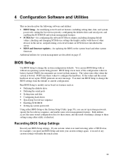
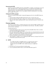
...up system passwords Using either utility is booted. Run BIOS Setup to change the BIOS settings from the default or current configuration. If your custom values ever need restoring (after a CMOS clear, for example), you can run BIOS Setup and enter your BIOS Setup settings. A record of other system firmware. BIOS Setup Use BIOS Setup to modify server board set features such as: • Defining the diskette drive • Defining the serial ports • Setting time and date • Configuring hard drives • Specifying boot device sequence • Enabling SCSI BIOS...
...up system passwords Using either utility is booted. Run BIOS Setup to change the BIOS settings from the default or current configuration. If your custom values ever need restoring (after a CMOS clear, for example), you can run BIOS Setup and enter your BIOS Setup settings. A record of other system firmware. BIOS Setup Use BIOS Setup to modify server board set features such as: • Defining the diskette drive • Defining the serial ports • Setting time and date • Configuring hard drives • Specifying boot device sequence • Enabling SCSI BIOS...

Product Guide
Page 40
... seconds or more; Install a jumper on the CMOS Clear jumper pins. 3. BIOS Setup Menu Navigation To: Get general help Move between menus Go to the previous item Go to the next Item Change the value of these two methods: • Use the front panel buttons: 1. Press the Reset button and hold it down the reset button, press the power button. 3. Using BIOS Setup To run BIOS Setup, boot the server and press the F2 key when prompted. Release...
... seconds or more; Install a jumper on the CMOS Clear jumper pins. 3. BIOS Setup Menu Navigation To: Get general help Move between menus Go to the previous item Go to the next Item Change the value of these two methods: • Use the front panel buttons: 1. Press the Reset button and hold it down the reset button, press the power button. 3. Using BIOS Setup To run BIOS Setup, boot the server and press the F2 key when prompted. Release...
Product Guide
Page 44
... BMC firmware, run the utility only if new firmware code is a DOS-based program used for text in the BIOS Setup user interface: 1. The Release Notes or other files listed on the screen, choosing to install one or more jumpers temporarily. Insert the diskette holding the BIOS update files into drive A and boot the server. 2. Follow the installation instructions that came with any other text or document files that you will need...
... BMC firmware, run the utility only if new firmware code is a DOS-based program used for text in the BIOS Setup user interface: 1. The Release Notes or other files listed on the screen, choosing to install one or more jumpers temporarily. Insert the diskette holding the BIOS update files into drive A and boot the server. 2. Follow the installation instructions that came with any other text or document files that you will need...
Product Guide
Page 48
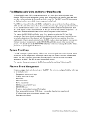
... and Sensor Data Records Field replaceable units (FRUs) are shipped from a source other than the front panel switch • Watchdog timer reset, power down, or power cycle • System restart (reboot) 48 Intel SPSH4 Server Platform Product Guide FRUs can store information-such as board serial number, part number, name, and asset tag-that can use the FRU/SDR Load Utility (page 62) to the BMC. The BMC stores...
... and Sensor Data Records Field replaceable units (FRUs) are shipped from a source other than the front panel switch • Watchdog timer reset, power down, or power cycle • System restart (reboot) 48 Intel SPSH4 Server Platform Product Guide FRUs can store information-such as board serial number, part number, name, and asset tag-that can use the FRU/SDR Load Utility (page 62) to the BMC. The BMC stores...

Product Guide
Page 49
... external modem or direct serial connection, for server hardware sensors. • Emergency management when the server is off or reset the server. • Run the System Setup Utility to change the server configuration. • Run diagnostics tools similar to a predefined destination on a separate ISM CD. System Management 49 You can configure the EMP by using the System Setup Utility (page 50). ISM applications interact with remote access software, such as the Direct Platform Control application in Intel Server Management. The server...
... external modem or direct serial connection, for server hardware sensors. • Emergency management when the server is off or reset the server. • Run the System Setup Utility to change the server configuration. • Run diagnostics tools similar to a predefined destination on a separate ISM CD. System Management 49 You can configure the EMP by using the System Setup Utility (page 50). ISM applications interact with remote access software, such as the Direct Platform Control application in Intel Server Management. The server...

Product Guide
Page 50
... system. 50 Intel SPSH4 Server Platform Product Guide If you choose to these settings using either the System Setup Utility or BIOS Setup (page 39), you have a workstation with the server. Boot to send alerts for platform events • Set up system passwords and security options. Alternatively, if you can run the SSU from a set of the hard disk. Creating SSU Diskettes You can specify the boot device sequence and set of DOS diskettes...
... system. 50 Intel SPSH4 Server Platform Product Guide If you choose to these settings using either the System Setup Utility or BIOS Setup (page 39), you have a workstation with the server. Boot to send alerts for platform events • Set up system passwords and security options. Alternatively, if you can run the SSU from a set of the hard disk. Creating SSU Diskettes You can specify the boot device sequence and set of DOS diskettes...

Product Guide
Page 138
...-plug PCI slots W 20-pin Power connector (P28) D Intelligent Chassis Management Bus (ICMB) X connector (P24) Y Floppy disk drive connector (P25) Serial port B connector (P17) E Hot-Plug Indicator Board (HPIB) connector Z USB #3 Header (P18) (P23) AA Front Panel Header (P19) F Back Panel I/O connectors (see page 134) G Intel® 82550 Ethernet controller BB IDE Connector (P13) CC SCSI LVD connectors (P4 and P7) H ATI Rage XL 2D/3D graphics accelerator J Intel® 82544 Ethernet controller DD Intelligent Platform Management Bus (IPMB) connector (P12) K Video RAM (VRAM) (4 MB...
...-plug PCI slots W 20-pin Power connector (P28) D Intelligent Chassis Management Bus (ICMB) X connector (P24) Y Floppy disk drive connector (P25) Serial port B connector (P17) E Hot-Plug Indicator Board (HPIB) connector Z USB #3 Header (P18) (P23) AA Front Panel Header (P19) F Back Panel I/O connectors (see page 134) G Intel® 82550 Ethernet controller BB IDE Connector (P13) CC SCSI LVD connectors (P4 and P7) H ATI Rage XL 2D/3D graphics accelerator J Intel® 82544 Ethernet controller DD Intelligent Platform Management Bus (IPMB) connector (P12) K Video RAM (VRAM) (4 MB...
Product Guide
Page 157
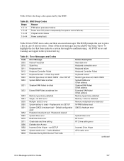
Error Messages and Codes Code Error Message 0200: Failure Fixed Disk 0210: Stuck Key 0211: Keyboard error 0212: Keyboard Controller Failed 0213: Keyboard locked - Default configuration used Password checksum bad - The BIOS prompts the user to highlight the fact that these indicate a system that might be malfunctioning. Passwords cleared System timer error Real time clock error Check date and time setting Diskette drive A error Incorrect Drive A type - Cache disabled Rebooted during BIOS boot at address line 0233: 0234: 0235: 0250: 0251: 0252...
Error Messages and Codes Code Error Message 0200: Failure Fixed Disk 0210: Stuck Key 0211: Keyboard error 0212: Keyboard Controller Failed 0213: Keyboard locked - Default configuration used Password checksum bad - The BIOS prompts the user to highlight the fact that these indicate a system that might be malfunctioning. Passwords cleared System timer error Real time clock error Check date and time setting Diskette drive A error Incorrect Drive A type - Cache disabled Rebooted during BIOS boot at address line 0233: 0234: 0235: 0250: 0251: 0252...

Product Guide
Page 165
... recovery jumper, 138 recovery POST codes, 152 updates, 43, 55 BIOS Setup, 39 BMC baseboard location, 136 beep codes, 152 boot block write enable jumper, 137 defined, 47 flash memory component, 136 force update jumper, 138 updating firmware, 44 BMC LAN alerts, 49 boot sector, write protecting, 37 booting the server, 32 boot device priority, 52 hot keys, 33 service partition, 33 troubleshooting, 119 bridge controller, 136 C cables front subchassis, 104 peripheral drives, 110 system, 104 cautions electrostatic discharge, 13 fans, replacing, 97 peripheral drives...
... recovery jumper, 138 recovery POST codes, 152 updates, 43, 55 BIOS Setup, 39 BMC baseboard location, 136 beep codes, 152 boot block write enable jumper, 137 defined, 47 flash memory component, 136 force update jumper, 138 updating firmware, 44 BMC LAN alerts, 49 boot sector, write protecting, 37 booting the server, 32 boot device priority, 52 hot keys, 33 service partition, 33 troubleshooting, 119 bridge controller, 136 C cables front subchassis, 104 peripheral drives, 110 system, 104 cautions electrostatic discharge, 13 fans, replacing, 97 peripheral drives...
Product Guide
Page 167
... port connector, 132 password clear jumper, 138 password on boot, 36 passwords, 37, 52 PCI add-in boards hot-plug operating system support, 91 installing, 93, 95 LEDs, 92 removing, 94, 96 types, 91 PCI-X bus bridge controller, 136 peripheral device bay, 133 peripheral drives, 110 cabling considerations, 110 installing, 112 removing, 111 physical specifications, 30 platform event management, 48, 56, 59 platform event paging, 49, 57 POST, 32 BIOS POST codes, 149 error messages and codes, 153 hot keys, 33 recovery BIOS POST codes, 152 troubleshooting, 120 Power button...
... port connector, 132 password clear jumper, 138 password on boot, 36 passwords, 37, 52 PCI add-in boards hot-plug operating system support, 91 installing, 93, 95 LEDs, 92 removing, 94, 96 types, 91 PCI-X bus bridge controller, 136 peripheral device bay, 133 peripheral drives, 110 cabling considerations, 110 installing, 112 removing, 111 physical specifications, 30 platform event management, 48, 56, 59 platform event paging, 49, 57 POST, 32 BIOS POST codes, 149 error messages and codes, 153 hot keys, 33 recovery BIOS POST codes, 152 troubleshooting, 120 Power button...

Product Guide
Page 168
..., 54 serial port A connector, 132 serial port B configuration jumpers, 138 serial port B connector, 131, 132, 136 serial remote access, 60 server components, 27 ServerWorks bridge controller, 136 service partition hot key, 33 installing, 34 setting up the server, 15, 29 site selection, 29 Sleep button, 131 Software Update Packages, 43 software updates, 42, 55 solving problems, See troubleshooting space requirements, 29 specifications, 127 DIMM memory, 139 physical, 30 power, 30 processors, 139 SCSI hard disk drives, 133 server board set, 135 site criteria, 30 SSU Configuration Save/Restore, 56...
..., 54 serial port A connector, 132 serial port B configuration jumpers, 138 serial port B connector, 131, 132, 136 serial remote access, 60 server components, 27 ServerWorks bridge controller, 136 service partition hot key, 33 installing, 34 setting up the server, 15, 29 site selection, 29 Sleep button, 131 Software Update Packages, 43 software updates, 42, 55 solving problems, See troubleshooting space requirements, 29 specifications, 127 DIMM memory, 139 physical, 30 power, 30 processors, 139 SCSI hard disk drives, 133 server board set, 135 site criteria, 30 SSU Configuration Save/Restore, 56...


