Product Specification
Page 2
New graphics for Mechanical Changes. Revision History Intel® Server Board SE7505VB2 Revision History Date January 2003 March 2003 April 2004 Revision Number 1.0 1.1 1.2 Modifications Initial Release Added memory cooling duct information, added section on BIOS event log, incorporated Technology Leadership terminology, and corrected miscellaneous minor technical details. ii Revision 1.2 Intel part number C32194-002
New graphics for Mechanical Changes. Revision History Intel® Server Board SE7505VB2 Revision History Date January 2003 March 2003 April 2004 Revision Number 1.0 1.1 1.2 Modifications Initial Release Added memory cooling duct information, added section on BIOS event log, incorporated Technology Leadership terminology, and corrected miscellaneous minor technical details. ii Revision 1.2 Intel part number C32194-002
Product Specification
Page 4
...or 66-MHz PCI Subsystem 34 5.2 Serial ATA Controller ...35 5.3 Video Controller ...36 5.3.1 Video Modes ...37 5.3.2 Video Memory Interface 37 5.3.3 Host Bus Interface...38 5.4 Network Interface Controller (NIC 39 5.4.1 NIC Connector and Status LEDs 39 5.5 Interrupt...Intel part number C32194-002 PCI I /O ...28 3.3.1 GPIOs ...29 3.3.2 Serial Ports...29 3.3.3 BIOS Flash...30 4. Clock Generation and Distribution 31 5. Introduction ...13 2. SE7505VB2 Server Board Overview 14 2.1 Intel® Server Board SE7505VB2 Feature Set 14 3. Table of Contents Intel® Server Board SE7505VB2...
...or 66-MHz PCI Subsystem 34 5.2 Serial ATA Controller ...35 5.3 Video Controller ...36 5.3.1 Video Modes ...37 5.3.2 Video Memory Interface 37 5.3.3 Host Bus Interface...38 5.4 Network Interface Controller (NIC 39 5.4.1 NIC Connector and Status LEDs 39 5.5 Interrupt...Intel part number C32194-002 PCI I /O ...28 3.3.1 GPIOs ...29 3.3.2 Serial Ports...29 3.3.3 BIOS Flash...30 4. Clock Generation and Distribution 31 5. Introduction ...13 2. SE7505VB2 Server Board Overview 14 2.1 Intel® Server Board SE7505VB2 Feature Set 14 3. Table of Contents Intel® Server Board SE7505VB2...
Product Specification
Page 5
SE7505VB2 Connectors...50 8.1 Main Power Connector 50 8.2 Memory Module Connector 51 8.3 Processor Socket...52 8.4 I2C Header ...55 8.5 PCI Slot Connector ...55 8.6 AGP 3.0 Pro50 Connector 58 8.7 Front Panel Connector 59 8.8 VGA Connector... Utility 67 10.1.1 If You Cannot Access Setup 67 10.1.2 Starting Setup...67 Revision 1.2 v Intel part number C32194-002 Intel® Server Board SE7505VB2 Table of Contents 5.5.4 IRQ Scan for PCIIRQ 41 5.6 PCI Error Handling...41 6. SE7505VB2 ACPI Implementation 48 7.1 ACPI ...48 7.1.1 Front Panel Switches 48 7.1.2 Wake up Sources (ACPI ...
SE7505VB2 Connectors...50 8.1 Main Power Connector 50 8.2 Memory Module Connector 51 8.3 Processor Socket...52 8.4 I2C Header ...55 8.5 PCI Slot Connector ...55 8.6 AGP 3.0 Pro50 Connector 58 8.7 Front Panel Connector 59 8.8 VGA Connector... Utility 67 10.1.1 If You Cannot Access Setup 67 10.1.2 Starting Setup...67 Revision 1.2 v Intel part number C32194-002 Intel® Server Board SE7505VB2 Table of Contents 5.5.4 IRQ Scan for PCIIRQ 41 5.6 PCI Error Handling...41 6. SE7505VB2 ACPI Implementation 48 7.1 ACPI ...48 7.1.1 Front Panel Switches 48 7.1.2 Wake up Sources (ACPI ...
Product Specification
Page 8
... 44 Figure 9. BIOS Recovery Jumper 92 Figure 12. System Recovery and Update Jumpers (J4J1 66 Figure 11. Turn on / off Timing...98 Figure 14. Memory Bank Label Definition 20 Figure 4. List of Figures Intel® Server Board SE7505VB2 List of Figures Figure 1. Memory Sub-system Block Diagram 18 Figure 3. Interrupt Routing Diagram 43 Figure 8.
... 44 Figure 9. BIOS Recovery Jumper 92 Figure 12. System Recovery and Update Jumpers (J4J1 66 Figure 11. Turn on / off Timing...98 Figure 14. Memory Bank Label Definition 20 Figure 4. List of Figures Intel® Server Board SE7505VB2 List of Figures Figure 1. Memory Sub-system Block Diagram 18 Figure 3. Interrupt Routing Diagram 43 Figure 8.
Product Specification
Page 9
...49 Table 20. Auxiliary CPU Power Connector Pin-out (J9K1 50 Table 23. SCSI HDD Header Pin-out (J3K2, J4K1 55 Table 26. Memory Bank Labels ...20 Table 3. Supported DDRs...23 Table 5. P64-B Arbitration Connections 35 Table 13. P64-C Arbitration Connections 35 Table 14. DIMM ... Table 18. NIC1 (10/100) Connector Pin-out (J5A1 60 Revision 1.2 ix Intel part number C32194-002 ICH4 GPIO Usage Table 26 Table 6. Processor Support Matrix 16 Table 2. Intel® Server Board SE7505VB2 List of Tables List of Tables Table 1. Auxiliary Signal Connector (J7K1 50 Table 22...
...49 Table 20. Auxiliary CPU Power Connector Pin-out (J9K1 50 Table 23. SCSI HDD Header Pin-out (J3K2, J4K1 55 Table 26. Memory Bank Labels ...20 Table 3. Supported DDRs...23 Table 5. P64-B Arbitration Connections 35 Table 13. P64-C Arbitration Connections 35 Table 14. DIMM ... Table 18. NIC1 (10/100) Connector Pin-out (J5A1 60 Revision 1.2 ix Intel part number C32194-002 ICH4 GPIO Usage Table 26 Table 6. Processor Support Matrix 16 Table 2. Intel® Server Board SE7505VB2 List of Tables List of Tables Table 1. Auxiliary Signal Connector (J7K1 50 Table 22...
Product Specification
Page 14
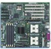
... of a high end workstation system as well. Flash ROM device for up to four DDR266 compliant ECC DDR DIMMs providing up to 8 GB of memory. 2.1 Intel® Server Board SE7505VB2 Feature Set The Intel Server Board SE7505VB2 supports the following feature set: Processor/FSB support - ICH4 I /O (floppy, serial, keyboard, mouse, parallel) and integrated hardware monitoring...
... of a high end workstation system as well. Flash ROM device for up to four DDR266 compliant ECC DDR DIMMs providing up to 8 GB of memory. 2.1 Intel® Server Board SE7505VB2 Feature Set The Intel Server Board SE7505VB2 supports the following feature set: Processor/FSB support - ICH4 I /O (floppy, serial, keyboard, mouse, parallel) and integrated hardware monitoring...
Product Specification
Page 16
...socket 2. Table 1. Processors with x4 DIMMs. 3.1.1 Processor Support The Intel Server Board SE7505VB2 supports one 64-bit/66MHz PCI bus via the P64H2, and the interface to 65A of the chipset provides an integrated memory controller, an 8-bit hub interface, and one processor is installed, ...it should be in the 604-pin FCPGA package. The support circuitry on the server board consists of the Intel® Server Board SE7505VB2. 3.1 Processor and Memory Subsystem The Intel® chipset E7505 provides a 36-bit address, 64-bit data processor host bus interface, operating at 533...
...socket 2. Table 1. Processors with x4 DIMMs. 3.1.1 Processor Support The Intel Server Board SE7505VB2 supports one 64-bit/66MHz PCI bus via the P64H2, and the interface to 65A of the chipset provides an integrated memory controller, an 8-bit hub interface, and one processor is installed, ...it should be in the 604-pin FCPGA package. The support circuitry on the server board consists of the Intel® Server Board SE7505VB2. 3.1 Processor and Memory Subsystem The Intel® chipset E7505 provides a 36-bit address, 64-bit data processor host bus interface, operating at 533...
Product Specification
Page 17
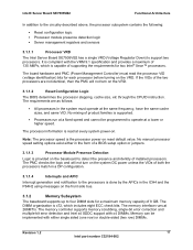
... processor VID (voltage identification) bits for each processor before turning on the front side bus. 3.1.2 Memory Subsystem The baseboard supports up to four DIMM slots for two Intel® Xeon™ processors. The PMC checks the logic and will not turn on the system...speed. If the VIDs of the two processors are as follows: All processors in the system must read at 266MT/s. Intel® Server Board SE7505VB2 Functional Architecture In addition to the circuitry described above, the processor subsystem contains the following: Reset configuration logic Processor module presence...
... processor VID (voltage identification) bits for each processor before turning on the front side bus. 3.1.2 Memory Subsystem The baseboard supports up to four DIMM slots for two Intel® Xeon™ processors. The PMC checks the logic and will not turn on the system...speed. If the VIDs of the two processors are as follows: All processors in the system must read at 266MT/s. Intel® Server Board SE7505VB2 Functional Architecture In addition to the circuitry described above, the processor subsystem contains the following: Reset configuration logic Processor module presence...
Product Specification
Page 18
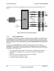
Functional Architecture Intel® Server Board SE7505VB2 The figure below provides a block diagram of qualified DIMMs is available at 266MT/s. A list of the memory sub-system implemented on the board. Therefore, the minimum main memory configuration is 4 x 2 GB or 8 GB. Only registered DDR266 compliant, ECC, DDR memory DIMMs will be supported ECC single-bit errors (SBE...
Functional Architecture Intel® Server Board SE7505VB2 The figure below provides a block diagram of qualified DIMMs is available at 266MT/s. A list of the memory sub-system implemented on the board. Therefore, the minimum main memory configuration is 4 x 2 GB or 8 GB. Only registered DDR266 compliant, ECC, DDR memory DIMMs will be supported ECC single-bit errors (SBE...
Product Specification
Page 19
... bank 2, both DIMMs in bank 1 must adhere to the specific orientation of these size memory parts, contact Intel Customer Support and request the SE7505VB2 server board memory cooling duct, part number C28482001. There are thermally at risk. Bank 1 contains DIMM socket...baseboard's signal integrity and cooling are optimized when memory banks are more difficult to each bank). Intel® Server Board SE7505VB2 Functional Architecture 3.1.2.2 Memory Configuration The memory interface between populated DIMMs. DIMM and memory configurations must be populated in the DIMM1A socket....
... bank 2, both DIMMs in bank 1 must adhere to the specific orientation of these size memory parts, contact Intel Customer Support and request the SE7505VB2 server board memory cooling duct, part number C28482001. There are thermally at risk. Bank 1 contains DIMM socket...baseboard's signal integrity and cooling are optimized when memory banks are more difficult to each bank). Intel® Server Board SE7505VB2 Functional Architecture 3.1.2.2 Memory Configuration The memory interface between populated DIMMs. DIMM and memory configurations must be populated in the DIMM1A socket....
Product Specification
Page 21
... at most only four bits can correct more efficient. 3.2 The Intel® E7505 Chipset The Intel Server Board SE7505VB2 is designed around the Intel E7505 chipset. These four bits must be adjacent, not random. I2C Addresses for Memory Module SMB Device DIMM 1A DIMM 1B DIMM 2A DIMM 2B Address...accepts inbound requests from the host (processor) bus and directs those accesses to memory or to boot the system. The MCH accepts access requests from the P64H2 and the ICH4. Intel® Server Board SE7505VB2 Functional Architecture 3.1.2.4 I2C Bus The I2C bus is used to correct up to...
... at most only four bits can correct more efficient. 3.2 The Intel® E7505 Chipset The Intel Server Board SE7505VB2 is designed around the Intel E7505 chipset. These four bits must be adjacent, not random. I2C Addresses for Memory Module SMB Device DIMM 1A DIMM 1B DIMM 2A DIMM 2B Address...accepts inbound requests from the host (processor) bus and directs those accesses to memory or to boot the system. The MCH accepts access requests from the P64H2 and the ICH4. Intel® Server Board SE7505VB2 Functional Architecture 3.1.2.4 I2C Bus The I2C bus is used to correct up to...
Product Specification
Page 22
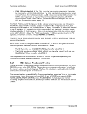
... supports 64 Mb, 128 Mb, 256 Mb, 512 Mb DRAM densities. Functional Architecture Intel® Server Board SE7505VB2 ICH4: I /O locations. If the cycle is 16 bits wide and operates at 266MT/s. The memory interface runs at 66 MHz with 512MT/s, providing over 1 GB per second of GPIO... I /O accesses to the system. 3.2.1 MCH Memory Architecture Overview The MCH supports a 144-bit wide memory sub-system that PCI bus. The DDR DIMM interface supports memory scrubbing, single-bit error correction, and multiple bit error detection and Intel x4 SDDC with the P64H2 through either the P64H2...
... supports 64 Mb, 128 Mb, 256 Mb, 512 Mb DRAM densities. Functional Architecture Intel® Server Board SE7505VB2 ICH4: I /O locations. If the cycle is 16 bits wide and operates at 266MT/s. The memory interface runs at 66 MHz with 512MT/s, providing over 1 GB per second of GPIO... I /O accesses to the system. 3.2.1 MCH Memory Architecture Overview The MCH supports a 144-bit wide memory sub-system that PCI bus. The DDR DIMM interface supports memory scrubbing, single-bit error correction, and multiple bit error detection and Intel x4 SDDC with the P64H2 through either the P64H2...
Product Specification
Page 23
...features provided by the MCH include the following: Full support of ECC on the processor bus Full support of Intel x4 SDDC on the memory interface with x4 DIMMs Twelve deep in-order queue, two deep defer queue Full support of previous generations like ...002 The HI interface allows the MCH to 8 GB of main memory and supports single- The MCH also increases the main memory interface bandwidth and maximum memory configuration with a 144-bit wide memory interface. Intel® Server Board SE7505VB2 Functional Architecture 3.2.1.1 DDR Configurations The DDR interface supports up to ...
...features provided by the MCH include the following: Full support of ECC on the processor bus Full support of Intel x4 SDDC on the memory interface with x4 DIMMs Twelve deep in-order queue, two deep defer queue Full support of previous generations like ...002 The HI interface allows the MCH to 8 GB of main memory and supports single- The MCH also increases the main memory interface bandwidth and maximum memory configuration with a 144-bit wide memory interface. Intel® Server Board SE7505VB2 Functional Architecture 3.2.1.1 DDR Configurations The DDR interface supports up to ...
Product Specification
Page 25
... acts as the central resource on this PCI interface. The USB specification defines the external connectors. Revision 1.2 25 Intel part number C32194-002 Intel® Server Board SE7505VB2 Functional Architecture The primary role of the ICH4 is to provide the gateway to all PC-compatible I /O panel... given chassis. The baseboard provides two 40-pin (2x20) IDE connectors to six USB connectors. The USB controller moves data between main memory and up to access the IDE functionality. All ports function identically and with Ultra DMA 100 capability Universal Serial Bus (USB) 2.0 interface...
... acts as the central resource on this PCI interface. The USB specification defines the external connectors. Revision 1.2 25 Intel part number C32194-002 Intel® Server Board SE7505VB2 Functional Architecture The primary role of the ICH4 is to provide the gateway to all PC-compatible I /O panel... given chassis. The baseboard provides two 40-pin (2x20) IDE connectors to six USB connectors. The USB controller moves data between main memory and up to access the IDE functionality. All ports function identically and with Ultra DMA 100 capability Universal Serial Bus (USB) 2.0 interface...
Product Specification
Page 30
... to control the power-on the back of BIOS and non- Functional Architecture Intel® Server Board SE7505VB2 3.3.2.3 Floppy Disk Controller The floppy disk controller (FDC) in the sIO is a high-performance 8-megabit memory component that allows various events to access the keyboard or mouse functions. The ...Keyboard and Mouse Two external PS/2 ports, located on and power-off the system. 3.3.3 BIOS Flash The board incorporates an Intel® N82802AC (FWH8) flash memory component. The flash device is connected through the LPC Bus from the ICH4 from the sIO. 30 Revision...
... to control the power-on the back of BIOS and non- Functional Architecture Intel® Server Board SE7505VB2 3.3.2.3 Floppy Disk Controller The floppy disk controller (FDC) in the sIO is a high-performance 8-megabit memory component that allows various events to access the keyboard or mouse functions. The ...Keyboard and Mouse Two external PS/2 ports, located on and power-off the system. 3.3.3 BIOS Flash The board incorporates an Intel® N82802AC (FWH8) flash memory component. The flash device is connected through the LPC Bus from the ICH4 from the sIO. 30 Revision...
Product Specification
Page 36
... different values. The SVGA subsystem supports a variety of modes, up to 1600 x 1200 resolution in the standard ATX I /O Subsystem Intel® Server Board SE7505VB2 The baseboard ships with the Silicon Image controller set to a second drive located on a different data channel. 5.3 Video Controller The baseboard... the AGP adapter becomes the secondary adapter under 3D. The baseboard provides a standard 15-pin VGA connector at the rear of video memory. RAID 1 configurations are primarily used for details on which option ROM to the other. The ATI Rage XL chip contains a SVGA...
... different values. The SVGA subsystem supports a variety of modes, up to 1600 x 1200 resolution in the standard ATX I /O Subsystem Intel® Server Board SE7505VB2 The baseboard ships with the Silicon Image controller set to a second drive located on a different data channel. 5.3 Video Controller The baseboard... the AGP adapter becomes the secondary adapter under 3D. The baseboard provides a standard 15-pin VGA connector at the rear of video memory. RAID 1 configurations are primarily used for details on which option ROM to the other. The ATI Rage XL chip contains a SVGA...
Product Specification
Page 37
... Supported Supported Supported Supported Supported Supported Supported Supported Supported Supported Supported Supported - - Revision 1.2 37 Intel part number C32194-002 The table specifies the minimum memory requirement for video memory. Video Modes 8 bpp Supported Supported Supported Supported Supported Supported Supported SE7505VB2 2D Video Mode Support 16 bpp 24 bpp 32 bpp Supported Supported Supported Supported...
... Supported Supported Supported Supported Supported Supported Supported Supported Supported Supported Supported Supported - - Revision 1.2 37 Intel part number C32194-002 The table specifies the minimum memory requirement for video memory. Video Modes 8 bpp Supported Supported Supported Supported Supported Supported Supported SE7505VB2 2D Video Mode Support 16 bpp 24 bpp 32 bpp Supported Supported Supported Supported...
Product Specification
Page 51
Intel® Server Board SE7505VB2 SE7505VB2 Connectors 8.2 Memory Module Connector The board has four DDR266 DIMM connectors and supports registered ECC DDR modules (Rev 1.0). Table 23. Front VDDQ /WE DQ41 /CAS VSS DQS5 ... NC 174 DQ60 175 DQ61 176 VSS 177 DM7 178 DQ62 179 DQ63 180 VDDQ 181 SA0 182 SA1 183 SA2 184 VDDSPD Revision 1.2 51 Intel part number C32194-002 DIMM Connectors (J9H1, J9J1, J9H2, J9J2) Pin Front Pin Front Pin 1 VREF 32 A5 62 2 DQ0 33 DQ24 63 3 VSS 34...
Intel® Server Board SE7505VB2 SE7505VB2 Connectors 8.2 Memory Module Connector The board has four DDR266 DIMM connectors and supports registered ECC DDR modules (Rev 1.0). Table 23. Front VDDQ /WE DQ41 /CAS VSS DQS5 ... NC 174 DQ60 175 DQ61 176 VSS 177 DM7 178 DQ62 179 DQ63 180 VDDQ 181 SA0 182 SA1 183 SA2 184 VDDSPD Revision 1.2 51 Intel part number C32194-002 DIMM Connectors (J9H1, J9J1, J9H2, J9J2) Pin Front Pin Front Pin 1 VREF 32 A5 62 2 DQ0 33 DQ24 63 3 VSS 34...
Product Specification
Page 67
... CMOS" position (enabled) In the two conditions listed above, after POST completes the memory test When you have moved the CMOS jumper on the BIOS and its functionality, contact your Intel field representative to obtain the Intel Server Board SE7505VB2 BIOS External Product Specification (Note that contains userselectable parameters. If a value is associated with...
... CMOS" position (enabled) In the two conditions listed above, after POST completes the memory test When you have moved the CMOS jumper on the BIOS and its functionality, contact your Intel field representative to obtain the Intel Server Board SE7505VB2 BIOS External Product Specification (Note that contains userselectable parameters. If a value is associated with...
Product Specification
Page 69
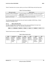
... or configure the option in BIOS Setup. On screen, the phrase Press Enter appears next to Setup program options Revision 1.2 69 Intel part number C32194-002 Table 48. Intel® Server Board SE7505VB2 BIOS Table 47 describes the on-screen options you will see this: On screen, an option is either a separate full.... Either the option is lost and how the power button operates Boot Specifies device from which the system boots System Provides information about vendor, processor, memory, peripherals Exit Saves or discards changes to the option.
... or configure the option in BIOS Setup. On screen, the phrase Press Enter appears next to Setup program options Revision 1.2 69 Intel part number C32194-002 Table 48. Intel® Server Board SE7505VB2 BIOS Table 47 describes the on-screen options you will see this: On screen, an option is either a separate full.... Either the option is lost and how the power button operates Boot Specifies device from which the system boots System Provides information about vendor, processor, memory, peripherals Exit Saves or discards changes to the option.


