Product Specification
Page 4
...88 6.5.3 SATA Connectors 89 6.5.4 Floppy Controller Connector 89 6.5.5 Serial Port Connectors 90 6.5.6 Keyboard and Mouse Connector 91 6.5.7 USB Connector...91 6.6 Fan Headers ...92 iv Revision 1.8 Intel Order Number: E14960-009 Table of Contents Intel® Server Boards S3200SH/S3210SH TPS 4.3 BIOS Setup Utility 44 4.3.1 Operation ...44 4.3.2 Server Platform Setup Screens 47 4.4 Loading BIOS Defaults 75 4.5 Multiple Boot Blocks 75 4.6 Recovery Mode...75 4.7 Intel® Matrix Storage Manager 76 4.8 Intel® Embedded Server RAID Technology II Support 76...
...88 6.5.3 SATA Connectors 89 6.5.4 Floppy Controller Connector 89 6.5.5 Serial Port Connectors 90 6.5.6 Keyboard and Mouse Connector 91 6.5.7 USB Connector...91 6.6 Fan Headers ...92 iv Revision 1.8 Intel Order Number: E14960-009 Table of Contents Intel® Server Boards S3200SH/S3210SH TPS 4.3 BIOS Setup Utility 44 4.3.1 Operation ...44 4.3.2 Server Platform Setup Screens 47 4.4 Loading BIOS Defaults 75 4.5 Multiple Boot Blocks 75 4.6 Recovery Mode...75 4.7 Intel® Matrix Storage Manager 76 4.8 Intel® Embedded Server RAID Technology II Support 76...
Product Specification
Page 10
.... Front Panel 24-Pin Header Pin-out (J1K2 87 Table 52. Keyboard and Mouse PS/2 Connectors Pin-out (J9A1 91 Table 59. Setup Utility - Setup Utility - Server Board Power Supply Voltage Specification 98 Table 68. POST Error Messages and Handling 84 Table 47. List of Tables Intel® Server Boards S3200SH/S3210SH TPS Table 34. CDROM Order Fields 69 Table 35. Setup Utility - Error Manager Screen Fields 73 Table 40. POST Progress Code LED Example 81 Table 45. POST Code Checkpoints 81...
.... Front Panel 24-Pin Header Pin-out (J1K2 87 Table 52. Keyboard and Mouse PS/2 Connectors Pin-out (J9A1 91 Table 59. Setup Utility - Setup Utility - Server Board Power Supply Voltage Specification 98 Table 68. POST Error Messages and Handling 84 Table 47. List of Tables Intel® Server Boards S3200SH/S3210SH TPS Table 34. CDROM Order Fields 69 Table 35. Setup Utility - Error Manager Screen Fields 73 Table 40. POST Progress Code LED Example 81 Table 45. POST Code Checkpoints 81...
Product Specification
Page 16
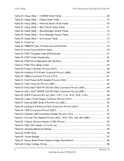
...; L and V board SKUs: Two PCI Express* x8 slots, one connected to the PCI Express* x8 interface of the MCH and the other connected to the PCI Express* x4 interface of the ICH ƒ HDD Interface o Six SATA II ports, 300 MB/s ƒ USB o Two USB 2.0 ports connected to the server rear panel o Two USB 2.0 ports connected to headers on the server board o One USB 2.0 port connected to an internal vertical connector ƒ LAN o One Gigabit Ethernet device (82541PI, MAC + PHY) connect to PCI interfaces...
...; L and V board SKUs: Two PCI Express* x8 slots, one connected to the PCI Express* x8 interface of the MCH and the other connected to the PCI Express* x4 interface of the ICH ƒ HDD Interface o Six SATA II ports, 300 MB/s ƒ USB o Two USB 2.0 ports connected to the server rear panel o Two USB 2.0 ports connected to headers on the server board o One USB 2.0 port connected to an internal vertical connector ƒ LAN o One Gigabit Ethernet device (82541PI, MAC + PHY) connect to PCI interfaces...
Product Specification
Page 18
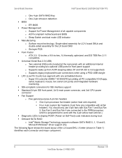
... Intel® Server Boards S3200SH/S3210SH TPS o One 4-pin SATA RAID Key o One 2-pin intrusion detection ƒ BIOS o EFI BIOS ƒ Power Management o Support for SSI interface support ƒ Standard 24-pin SSI front panel, 2x12 main power connector, and 2x4 CPU power connector ƒ Fan Support o Five general purpose 4-pin fan headers ƒ One 4-pin processor fan header (active heat sink required) ƒ Four 4-pin system fan headers (3-pin fans are connected to work with Sys Fan 1 and Sys Fan 2; Microsoft Windows* driver support only. Sys Fan 3 and Sys Fan 4 are compatible...
... Intel® Server Boards S3200SH/S3210SH TPS o One 4-pin SATA RAID Key o One 2-pin intrusion detection ƒ BIOS o EFI BIOS ƒ Power Management o Support for SSI interface support ƒ Standard 24-pin SSI front panel, 2x12 main power connector, and 2x4 CPU power connector ƒ Fan Support o Five general purpose 4-pin fan headers ƒ One 4-pin processor fan header (active heat sink required) ƒ Four 4-pin system fan headers (3-pin fans are connected to work with Sys Fan 1 and Sys Fan 2; Microsoft Windows* driver support only. Sys Fan 3 and Sys Fan 4 are compatible...
Product Specification
Page 21
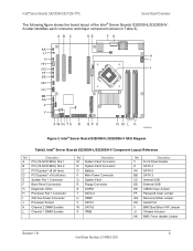
...2X4 Aux Power Connector J Processor Socket K Channel 2 DIMM Sockets L Channel 1 DIMM Sockets Ref Description M System Fan4 Connector N System Fan3 Connector O Battery P Main Power Connector Q System Fan2 R Floppy Connector S SGPIO T SATA 0 U HSBP V SATA1 W SATA2 X IPMB Ref Description Y Front Panel Header Z SATA 4 AA SATA 5 BB SATA 3 CC Internal USB DD External USB EE CMOS Clear Jumper FF Password Clear Jumper GG Recovery Mode Jumper HH Serial Port II BMC Boot Block WP Jumper JJ Chassis Intrusion KK BMC Force Update Jumper Revision 1.8 9 Intel Order Number...
...2X4 Aux Power Connector J Processor Socket K Channel 2 DIMM Sockets L Channel 1 DIMM Sockets Ref Description M System Fan4 Connector N System Fan3 Connector O Battery P Main Power Connector Q System Fan2 R Floppy Connector S SGPIO T SATA 0 U HSBP V SATA1 W SATA2 X IPMB Ref Description Y Front Panel Header Z SATA 4 AA SATA 5 BB SATA 3 CC Internal USB DD External USB EE CMOS Clear Jumper FF Password Clear Jumper GG Recovery Mode Jumper HH Serial Port II BMC Boot Block WP Jumper JJ Chassis Intrusion KK BMC Force Update Jumper Revision 1.8 9 Intel Order Number...
Product Specification
Page 27
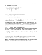
... maintain compatibility with 32-bit software written for VTT) pin before turning on . If the VTTEN pin of a BIOS setup option or jumpers. Note: The processor speed is compliant with supported 64-bit operating systems and applications. 3.1.1 Processor Voltage Regulator Down (VRD) The server board has a VRD (Voltage Regulator Down) to as the Intel® LGA775 socket. It is the processor power-on the VRD. 3.1.2 Reset Configuration Logic The BIOS determines the processor stepping and processor cache size through...
... maintain compatibility with 32-bit software written for VTT) pin before turning on . If the VTTEN pin of a BIOS setup option or jumpers. Note: The processor speed is compliant with supported 64-bit operating systems and applications. 3.1.1 Processor Voltage Regulator Down (VRD) The server board has a VRD (Voltage Regulator Down) to as the Intel® LGA775 socket. It is the processor power-on the VRD. 3.1.2 Reset Configuration Logic The BIOS determines the processor stepping and processor cache size through...

Product Specification
Page 48
... for BMC support ƒ Two Fully Functional Serial Ports, compatible with the 16C550 ƒ Serial IRQ Support ƒ SMI/SCI/PME Support ƒ ACPI Compliant ƒ Up to 16 Shared GPIO ports ƒ Programmable Wake-up Event Support ƒ Plug and Play Register Set ƒ Power Supply Control ƒ Watchdog timer compliant with Microsoft SHDG ƒ LPC to SPI bridge for system BIOS support ƒ Real Time Clock (RTC...
... for BMC support ƒ Two Fully Functional Serial Ports, compatible with the 16C550 ƒ Serial IRQ Support ƒ SMI/SCI/PME Support ƒ ACPI Compliant ƒ Up to 16 Shared GPIO ports ƒ Programmable Wake-up Event Support ƒ Plug and Play Register Set ƒ Power Supply Control ƒ Watchdog timer compliant with Microsoft SHDG ƒ LPC to SPI bridge for system BIOS support ƒ Real Time Clock (RTC...

Product Specification
Page 51
... Intel® 82541 Gigabit Ethernet Controller is a single, compact component with the ICH9 using PCI 32 bit/33MHz. The LCI interface operates using eight single ended signals, one clock, three transmit, three receive, and one receive pair. The server board uses this device along with analog display capabilities. This interface operates using a lower frequency LAN Connect Interface (LCI). The PHY is also interfaced to support the onboard video controller. The device...
... Intel® 82541 Gigabit Ethernet Controller is a single, compact component with the ICH9 using PCI 32 bit/33MHz. The LCI interface operates using eight single ended signals, one clock, three transmit, three receive, and one receive pair. The server board uses this device along with analog display capabilities. This interface operates using a lower frequency LAN Connect Interface (LCI). The PHY is also interfaced to support the onboard video controller. The device...

Product Specification
Page 62
.... To access this screen, the user selects the option they want to modify the selected field. Setup Utility - Use [Enter] or [Tab] key to configure several options such as processor, memory, SATA controller, and so forth. Advanced Screen Display 50 Revision 1.8 Intel Order Number: E14960-009 On this screen from the Main screen, press the right arrow until the Advanced screen is selected. Use [+] or [-] key to configure. Intel® Server Boards S3200SH/S3210SH TPS System BIOS Setup Item System...
.... To access this screen, the user selects the option they want to modify the selected field. Setup Utility - Use [Enter] or [Tab] key to configure several options such as processor, memory, SATA controller, and so forth. Advanced Screen Display 50 Revision 1.8 Intel Order Number: E14960-009 On this screen from the Main screen, press the right arrow until the Advanced screen is selected. Use [+] or [-] key to configure. Intel® Server Boards S3200SH/S3210SH TPS System BIOS Setup Item System...

Product Specification
Page 68
Intel® Server Boards S3200SH/S3210SH TPS System BIOS Setup Item Onboard SATA Controller Configure SATA as independent SATA drives [RAID] - SATA controller will be in RAID mode and the Intel® RAID for Serial ATA option ROM will be configured in RAID Mode. The SATA drives will execute. [IDE] - Information only: This field is unavailable when RAID Mode is enabled. To access this screen from the Main screen, select Advanced | Serial Port. 56 Revision 1.8 Intel Order Number: E14960-009 Information only: This field is unavailable when RAID Mode is enabled. Setup Utility -...
Intel® Server Boards S3200SH/S3210SH TPS System BIOS Setup Item Onboard SATA Controller Configure SATA as independent SATA drives [RAID] - SATA controller will be in RAID mode and the Intel® RAID for Serial ATA option ROM will be configured in RAID Mode. The SATA drives will execute. [IDE] - Information only: This field is unavailable when RAID Mode is enabled. To access this screen from the Main screen, select Advanced | Serial Port. 56 Revision 1.8 Intel Order Number: E14960-009 Information only: This field is unavailable when RAID Mode is enabled. Setup Utility -...

Product Specification
Page 72
... to enable and set the user and administrative password and to boot or wake the system. Information only. 12 hex digits of the MAC address. Setup Utility - Load the embedded option ROM for system video. To access this screen from the Main screen, select the Security option. 60 Revision 1.8 Intel Order Number: E14960-009 PCI Configuration Screen Display Setup Item Dual Monitor Video Onboard NIC ROM NIC 1 MAC Address NIC 2 MAC Address Table 27. Setup Utility - The onboard video controller will be used . Intel® Server Boards...
... to enable and set the user and administrative password and to boot or wake the system. Information only. 12 hex digits of the MAC address. Setup Utility - Load the embedded option ROM for system video. To access this screen from the Main screen, select the Security option. 60 Revision 1.8 Intel Order Number: E14960-009 PCI Configuration Screen Display Setup Item Dual Monitor Video Onboard NIC ROM NIC 1 MAC Address NIC 2 MAC Address Table 27. Setup Utility - The onboard video controller will be used . Intel® Server Boards...
Product Specification
Page 73
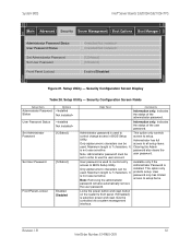
...installed. Only alphanumeric characters can be controlled via a system management interface. User password only has limited access to BIOS Setup Utility. System BIOS Intel® Server Boards S3200SH/S3210SH TPS Main Advanced Security Server Management Boot Options Boot Manager Administrator Password Status User Password Status Set Administrator Password Set User Password Front Panel Lockout [1234abcd] [1234abcd] Enabled/Disabled Figure 21. Note: Administrator password must be used . Available only if the Administrator Password is used to control entry access to setup...
...installed. Only alphanumeric characters can be controlled via a system management interface. User password only has limited access to BIOS Setup Utility. System BIOS Intel® Server Boards S3200SH/S3210SH TPS Main Advanced Security Server Management Boot Options Boot Manager Administrator Password Status User Password Status Set Administrator Password Set User Password Front Panel Lockout [1234abcd] [1234abcd] Enabled/Disabled Figure 21. Note: Administrator password must be used . Available only if the Administrator Password is used to control entry access to setup...

Product Specification
Page 75
... for this screen from the Server Management screen. To access this feature. If the OS does not complete booting before the timer expires, the BMC will use to configure the watchdog timer. System BIOS Intel® Server Boards S3200SH/S3210SH TPS Setup Item Clear System Event Log FRB-2 Enable O/S Boot Watchdog Timer O/S Boot Watchdog Timer Policy O/S Boot Watchdog Timer Timeout Console Redirection System Information Options Enabled Disabled Enabled Disabled Enabled Disabled Power Off Reset 5 minutes 10...
... for this screen from the Server Management screen. To access this feature. If the OS does not complete booting before the timer expires, the BMC will use to configure the watchdog timer. System BIOS Intel® Server Boards S3200SH/S3210SH TPS Setup Item Clear System Event Log FRB-2 Enable O/S Boot Watchdog Timer O/S Boot Watchdog Timer Policy O/S Boot Watchdog Timer Timeout Console Redirection System Information Options Enabled Disabled Enabled Disabled Enabled Disabled Power Off Reset 5 minutes 10...
Product Specification
Page 87
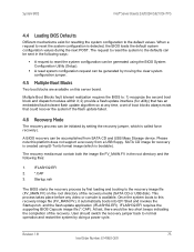
... this server board. System BIOS Intel® Server Boards S3200SH/S3210SH TPS 4.4 Loading BIOS Defaults Different mechanisms exist for resetting the system configuration to reset the system configuration is called force recovery). and the flash update application (IFLASH32.EFI). Please note this recovery image file (FV_MAIN.FV), it ; 2) provide a flash update interface (for utility) that could recover the system if the flash update failed. 4.6 Recovery Mode The recovery process can be accomplished from a USB floppy. Revision 1.8 75 Intel Order...
... this server board. System BIOS Intel® Server Boards S3200SH/S3210SH TPS 4.4 Loading BIOS Defaults Different mechanisms exist for resetting the system configuration to reset the system configuration is called force recovery). and the flash update application (IFLASH32.EFI). Please note this recovery image file (FV_MAIN.FV), it ; 2) provide a flash update interface (for utility) that could recover the system if the flash update failed. 4.6 Recovery Mode The recovery process can be accomplished from a USB floppy. Revision 1.8 75 Intel Order...
Product Specification
Page 89
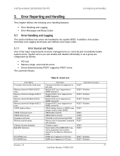
.... CMOS battery failure or CMOS clear jumper is set Keyboard not found during POST, logged as follows: ƒ PCI bus ƒ Memory single- and multi-bit errors ƒ Errors detected during POST Memory size is decreased compared with last boot Chassis is to clear CMOS. Multi-bit ECC error happened on PCI bus When Error Is Caught POST POST / Runtime POST / Runtime POST / Runtime POST / Runtime POST POST POST POST POST POST POST POST / Runtime POST / Runtime Revision 1.8 77 Intel Order Number: E14960-009 PERR error happens on PCI bus SERR error happens on DIMM channel B. Error...
.... CMOS battery failure or CMOS clear jumper is set Keyboard not found during POST, logged as follows: ƒ PCI bus ƒ Memory single- and multi-bit errors ƒ Errors detected during POST Memory size is decreased compared with last boot Chassis is to clear CMOS. Multi-bit ECC error happened on PCI bus When Error Is Caught POST POST / Runtime POST / Runtime POST / Runtime POST / Runtime POST POST POST POST POST POST POST POST / Runtime POST / Runtime Revision 1.8 77 Intel Order Number: E14960-009 PERR error happens on PCI bus SERR error happens on DIMM channel B. Error...
Product Specification
Page 97
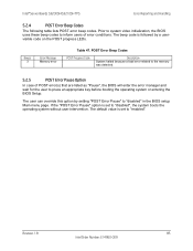
... system boots the operating system without user-intervention. If the "POST Error Pause" option is set to "enabled". Beeps 3 Error Message Memory error Table 47. The user can override this option by a uservisible code on the POST progress LEDs. Prior to system video initialization, the BIOS uses these beep codes to inform users of POST error(s) that are listed as "Pause", the BIOS will enter the error manager and wait for the user to "disabled" in the BIOS setup Main menu page. Revision 1.8 85 Intel...
... system boots the operating system without user-intervention. If the "POST Error Pause" option is set to "enabled". Beeps 3 Error Message Memory error Table 47. The user can override this option by a uservisible code on the POST progress LEDs. Prior to system video initialization, the BIOS uses these beep codes to inform users of POST error(s) that are listed as "Pause", the BIOS will enter the error manager and wait for the user to "disabled" in the BIOS setup Main menu page. Revision 1.8 85 Intel...

Product Specification
Page 105
...Table 62 shows the pin-out definition for HDD LED connection. Connectors and Jumper Blocks Keyboard Intel® Server Boards S3200SH/S3210SH TPS Serial A LAN Mouse VGA POST Code LED USB Figure 36. Chassis Intrusion Header (J1B2) Pin-out Pin 1 2 Signal Name FP_INTRUDER_HDR_P1 FP_INTRUDER_HDR_N 6.7.3 HDD Active LED Header There is a 4-pin IPMB connector jumper. This jumper is reserved for connecting to the Intel® Entry Server Chassis SC5299-E hot-swap backplane. This jumper is reserved for PCI add-in cards that support a chassis intrusion switch.
...Table 62 shows the pin-out definition for HDD LED connection. Connectors and Jumper Blocks Keyboard Intel® Server Boards S3200SH/S3210SH TPS Serial A LAN Mouse VGA POST Code LED USB Figure 36. Chassis Intrusion Header (J1B2) Pin-out Pin 1 2 Signal Name FP_INTRUDER_HDR_P1 FP_INTRUDER_HDR_N 6.7.3 HDD Active LED Header There is a 4-pin IPMB connector jumper. This jumper is reserved for connecting to the Intel® Entry Server Chassis SC5299-E hot-swap backplane. This jumper is reserved for PCI add-in cards that support a chassis intrusion switch.

Product Specification
Page 106
...connecting to the Intel® Entry Server Chassis SC5299-E SATA hot-swap backplane. 6.8 Jumper Blocks This section describes the configuration jumper options on LX J1E2 J1E2 J1J2 J1E1 J1D2 J1B1 J3A1 J1C2 J1D1 Function Clear CMOS content Clear CMOS Password BIOS recovery BMC Force Update Mode BMC Firmware Flash boot block protection Definition 1-2: Normal 2-3: Clear CMOS 1-2: Protect Password 2-3: Clear Password 1-2: Normal boot 2-3: Recovery mode 1-2: BMC in normal mode 2-3: BMC in force update mode 1-2: Write Protection controlled by going into BIOS setup. For instructions...
...connecting to the Intel® Entry Server Chassis SC5299-E SATA hot-swap backplane. 6.8 Jumper Blocks This section describes the configuration jumper options on LX J1E2 J1E2 J1J2 J1E1 J1D2 J1B1 J3A1 J1C2 J1D1 Function Clear CMOS content Clear CMOS Password BIOS recovery BMC Force Update Mode BMC Firmware Flash boot block protection Definition 1-2: Normal 2-3: Clear CMOS 1-2: Protect Password 2-3: Clear Password 1-2: Normal boot 2-3: Recovery mode 1-2: BMC in normal mode 2-3: BMC in force update mode 1-2: Write Protection controlled by going into BIOS setup. For instructions...
Product Specification
Page 107
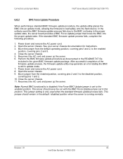
... the BMC Force Update jumper set to load safely onto the flash device. Move the jumper from the enabled position, covering pins 2 and 3 to the enabled position, covering pins 2 and 3. 4. Power down and remove the AC power cord. 2. The server should remain in update mode. 7. Revision 1.8 95 Intel Order Number: E14960-009 Connectors and Jumper Blocks Intel® Server Boards S3200SH/S3210SH TPS 6.8.2 BMC Force Update Procedure When performing a standard BMC firmware update procedure, the update utility places the...
... the BMC Force Update jumper set to load safely onto the flash device. Move the jumper from the enabled position, covering pins 2 and 3 to the enabled position, covering pins 2 and 3. 4. Power down and remove the AC power cord. 2. The server should remain in update mode. 7. Revision 1.8 95 Intel Order Number: E14960-009 Connectors and Jumper Blocks Intel® Server Boards S3200SH/S3210SH TPS 6.8.2 BMC Force Update Procedure When performing a standard BMC firmware update procedure, the update utility places the...

Product Specification
Page 125
... server board. Data Carrier Detect Dual In-Line Memory Module Direct Memory Access Distributed Management Task Force Error Correcting Code Electromagnetic Compatibility External Product Specification Extended System Configuration Data Floppy Disk Controller First-In, First-Out Fault Resilient Booting Field replaceable unit Front Side Bus 1024 MB 1 Gbit General purpose I/O Globally Unique ID Hertz (1 cycle/second) Hardware Design Guide Inter-integrated circuit bus Intel® architecture Intelligent Chassis Management Bus Internal error Inter Module Bus...
... server board. Data Carrier Detect Dual In-Line Memory Module Direct Memory Access Distributed Management Task Force Error Correcting Code Electromagnetic Compatibility External Product Specification Extended System Configuration Data Floppy Disk Controller First-In, First-Out Fault Resilient Booting Field replaceable unit Front Side Bus 1024 MB 1 Gbit General purpose I/O Globally Unique ID Hertz (1 cycle/second) Hardware Design Guide Inter-integrated circuit bus Intel® architecture Intelligent Chassis Management Bus Internal error Inter Module Bus...


