

Intel Desktop Board DX79SI Technical Product Specification
Page 8
...3.5 Legacy USB Support 69 3.6 BIOS Updates 70 3.6.1 Language Support 70 3.6.2 Custom Splash Screen 71 3.7 BIOS Recovery 71 3.8 Boot Options 72 3.8.1 Optical Drive Boot 72 3.8.2 Network Boot 72 3.8.3 Booting Without Attached Devices 72 3.8.4 Changing the Default Boot Device During POST 72 3.9 Adjusting Boot Speed 73 3.9.1 Peripheral Selection and Configuration 73 3.9.2 BIOS Boot Optimizations 73 3.10 BIOS Security Features 74 3.11 BIOS Performance Features 75 4 Error Messages and Beep Codes 4.1 Speaker 77 4.2 BIOS Beep Codes 77 4.3 Front-panel Power LED Blink Codes 78 4.4 BIOS...
...3.5 Legacy USB Support 69 3.6 BIOS Updates 70 3.6.1 Language Support 70 3.6.2 Custom Splash Screen 71 3.7 BIOS Recovery 71 3.8 Boot Options 72 3.8.1 Optical Drive Boot 72 3.8.2 Network Boot 72 3.8.3 Booting Without Attached Devices 72 3.8.4 Changing the Default Boot Device During POST 72 3.9 Adjusting Boot Speed 73 3.9.1 Peripheral Selection and Configuration 73 3.9.2 BIOS Boot Optimizations 73 3.10 BIOS Security Features 74 3.11 BIOS Performance Features 75 4 Error Messages and Beep Codes 4.1 Speaker 77 4.2 BIOS Beep Codes 77 4.3 Front-panel Power LED Blink Codes 78 4.4 BIOS...

Intel Desktop Board DX79SI Technical Product Specification
Page 10
... x Main Power Connector 54 23. BIOS Setup Configuration Jumper Settings 59 27. BIOS Setup Program Menu Bar 68 32. Supervisor and User Password Functions 74 36. BIOS Beep Codes 77 37. Chassis Intrusion Header 52 20. Front Panel Header 55 24. Recommended Power Supply Current Values 61 28. Fan Header Current Capability 62 29. Boot Device Menu Options 72 35. EMC Regulations 89 44. USB 3.0 Connector 52 19. Environmental Specifications 65 31. Port 80h POST Code Ranges 79 40. Typical Port 80h POST Sequence 84 42. BIOS Setup...
... x Main Power Connector 54 23. BIOS Setup Configuration Jumper Settings 59 27. BIOS Setup Program Menu Bar 68 32. Supervisor and User Password Functions 74 36. BIOS Beep Codes 77 37. Chassis Intrusion Header 52 20. Front Panel Header 55 24. Recommended Power Supply Current Values 61 28. Fan Header Current Capability 62 29. Boot Device Menu Options 72 35. EMC Regulations 89 44. USB 3.0 Connector 52 19. Environmental Specifications 65 31. Port 80h POST Code Ranges 79 40. Typical Port 80h POST Sequence 84 42. BIOS Setup...
Intel Desktop Board DX79SI Technical Product Specification
Page 22
Intel Desktop Board DX79SI Technical Product Specification The underlying SATA functionality is transparent to use new low-voltage power connectors and require adapters or power supplies equipped with low-voltage power connectors. The SATA controller can operate in the operating system installation process. 22 data striping • RAID 1 - data striping and mirroring • RAID 5 - In Native mode, standard PCI Conventional bus resource steering is the preferred mode for configurations using the F6 switch in both AHCI and RAID without the...
Intel Desktop Board DX79SI Technical Product Specification The underlying SATA functionality is transparent to use new low-voltage power connectors and require adapters or power supplies equipped with low-voltage power connectors. The SATA controller can operate in the operating system installation process. 22 data striping • RAID 1 - data striping and mirroring • RAID 5 - In Native mode, standard PCI Conventional bus resource steering is the preferred mode for configurations using the F6 switch in both AHCI and RAID without the...

Intel Desktop Board DX79SI Technical Product Specification
Page 26
... Specification 1.10 LAN Subsystem The Intel GbE Dual LAN subsystem consists of the following: • Intel 82579L and Intel 82574L Gigabit Ethernet Controllers (10/100/1000 Mbits/s) • Intel X79 Express Chipset • RJ-45 LAN connectors with integrated status LEDs Additional features of the LAN subsystem include: • CSMA/CD protocol engine • LAN connect interface between the PCH and the LAN controller • Conventional PCI bus power management ACPI technology support LAN wake...
... Specification 1.10 LAN Subsystem The Intel GbE Dual LAN subsystem consists of the following: • Intel 82579L and Intel 82574L Gigabit Ethernet Controllers (10/100/1000 Mbits/s) • Intel X79 Express Chipset • RJ-45 LAN connectors with integrated status LEDs Additional features of the LAN subsystem include: • CSMA/CD protocol engine • LAN connect interface between the PCH and the LAN controller • Conventional PCI bus power management ACPI technology support LAN wake...

Intel Desktop Board DX79SI Technical Product Specification
Page 68
... configure PCI devices. BIOS Setup Program Menu Bar Maintenance Main Configura- When a user turns on the system after adding a PCI card, the BIOS automatically configures interrupts, the I/O space, and other system resources. tion Performance Security Clears passwords and displays processor information Displays processor and memory configuration Configures advanced features available through the chipset Configures Memory, Bus and Processor overrides Sets passwords and security features Power Configures power management features and power supply controls Boot Selects boot options...
... configure PCI devices. BIOS Setup Program Menu Bar Maintenance Main Configura- When a user turns on the system after adding a PCI card, the BIOS automatically configures interrupts, the I/O space, and other system resources. tion Performance Security Clears passwords and displays processor information Displays processor and memory configuration Configures advanced features available through the chipset Configures Memory, Bus and Processor overrides Sets passwords and security features Power Configures power management features and power supply controls Boot Selects boot options...

Intel Desktop Board DX79SI Technical Product Specification
Page 72
...diskette drive, hard drive, USB drive, USB flash drive, optical drive, or the network. Intel Desktop Board DX79SI Technical Product Specification 3.8 Boot Options In the BIOS Setup program, the user can be the first boot device, the hard drive second, and the optical drive third. Under the Boot menu in card with a remote boot ROM installed. Table 35 lists the boot device menu options. The default setting is listed as set to boot from the LAN. Boot Device Menu Options Boot Device Menu Function Keys or Description Selects a default boot device Exits the menu, saves changes...
...diskette drive, hard drive, USB drive, USB flash drive, optical drive, or the network. Intel Desktop Board DX79SI Technical Product Specification 3.8 Boot Options In the BIOS Setup program, the user can be the first boot device, the hard drive second, and the optical drive third. Under the Boot menu in card with a remote boot ROM installed. Table 35 lists the boot device menu options. The default setting is listed as set to boot from the LAN. Boot Device Menu Options Boot Device Menu Function Keys or Description Selects a default boot device Exits the menu, saves changes...

Intel Desktop Board DX79SI Technical Product Specification
Page 79
... - 0x35 Recovery 0x36 - 0x3F Platform DXE driver 0x41 - 0x4F CPU Initialization (PEI, DXE, SMM) 0x50 - 0x5F I /O port 80h. Error Messages and Beep Codes 4.5 Port 80h POST Codes During the POST, the BIOS generates diagnostic progress codes (POST codes) to S5. 0x10, 0x20, 0x30, 0x40, 0x50 0x08 - 0x0F Resuming from SX states. 0x10 - 0x20 - Port 80h POST Code Ranges Range Subsystem 0x00 - 0x05 Entering SX states S0 to I /O Buses: PCI, USB, ATA...
... - 0x35 Recovery 0x36 - 0x3F Platform DXE driver 0x41 - 0x4F CPU Initialization (PEI, DXE, SMM) 0x50 - 0x5F I /O port 80h. Error Messages and Beep Codes 4.5 Port 80h POST Codes During the POST, the BIOS generates diagnostic progress codes (POST codes) to S5. 0x10, 0x20, 0x30, 0x40, 0x50 0x08 - 0x0F Resuming from SX states. 0x10 - 0x20 - Port 80h POST Code Ranges Range Subsystem 0x00 - 0x05 Entering SX states S0 to I /O Buses: PCI, USB, ATA...

Product Guide for Intel Desktop Board DX79SI
Page 3
... attention to update the BIOS 4 Configuring for RAID: information about configuring your system for other PC or embedded non-PC applications or other environments, such as Information Technology Equipment (I.T.E.) for use in personal computers (PC) for Intel® Desktop Board DX79SI. may not be supported without further evaluation by Intel. Preface This Product Guide gives information about board layout, component installation, BIOS update, and regulatory requirements for installation in homes...
... attention to update the BIOS 4 Configuring for RAID: information about configuring your system for other PC or embedded non-PC applications or other environments, such as Information Technology Equipment (I.T.E.) for use in personal computers (PC) for Intel® Desktop Board DX79SI. may not be supported without further evaluation by Intel. Preface This Product Guide gives information about board layout, component installation, BIOS update, and regulatory requirements for installation in homes...

Product Guide for Intel Desktop Board DX79SI
Page 5
... 11 Desktop Board Components 12 Processor ...14 System Memory 15 Memory Configurations 16 Intel® X79 Express Chipset 17 USB Support ...17 USB 3.0 ...17 USB 2.0 ...17 Serial ATA...17 Audio Subsystem 18 LAN Subsystem 18 Legacy I/O ...20 Expandability...20 BIOS ...20 Serial ATA and IDE Auto Configuration 21 PCI and PCI Express* Auto Configuration 21 Security Passwords 21 Back to BIOS Button 21 Hardware Management 22 Hardware Monitoring and Fan Speed Control 22 Chassis Intrusion 22 Power Management 23 Software Support 23 ACPI 23 Hardware Support 23 Power Connectors 23 Fan...
... 11 Desktop Board Components 12 Processor ...14 System Memory 15 Memory Configurations 16 Intel® X79 Express Chipset 17 USB Support ...17 USB 3.0 ...17 USB 2.0 ...17 Serial ATA...17 Audio Subsystem 18 LAN Subsystem 18 Legacy I/O ...20 Expandability...20 BIOS ...20 Serial ATA and IDE Auto Configuration 21 PCI and PCI Express* Auto Configuration 21 Security Passwords 21 Back to BIOS Button 21 Hardware Management 22 Hardware Monitoring and Fan Speed Control 22 Chassis Intrusion 22 Power Management 23 Software Support 23 ACPI 23 Hardware Support 23 Power Connectors 23 Fan...
Product Guide for Intel Desktop Board DX79SI
Page 6
...51 USB 3.0 Connector 51 Consumer IR (CIR) Headers 52 USB 2.0 Headers 53 Front Panel Header 53 Alternate Front Panel Power LED Header 54 Connecting to the Audio System 54 Connecting Chassis Fan and Power Supply Cables 55 Connecting Chassis Fan Cables 55 Connecting Power Supply Cables 56 Setting the BIOS Configuration Jumper 57 Clearing Passwords 58 Replacing the Battery 59 Installing the WiFi/Bluetooth* Module in Your Chassis 64 Connecting the Remote Thermal Probe 65 3 Updating the BIOS Updating the BIOS with the Intel® Express BIOS Update Utility 67 Updating the BIOS Using...
...51 USB 3.0 Connector 51 Consumer IR (CIR) Headers 52 USB 2.0 Headers 53 Front Panel Header 53 Alternate Front Panel Power LED Header 54 Connecting to the Audio System 54 Connecting Chassis Fan and Power Supply Cables 55 Connecting Chassis Fan Cables 55 Connecting Power Supply Cables 56 Setting the BIOS Configuration Jumper 57 Clearing Passwords 58 Replacing the Battery 59 Installing the WiFi/Bluetooth* Module in Your Chassis 64 Connecting the Remote Thermal Probe 65 3 Updating the BIOS Updating the BIOS with the Intel® Express BIOS Update Utility 67 Updating the BIOS Using...
Product Guide for Intel Desktop Board DX79SI
Page 7
... to the Processor Fan Header 41 17. Installing a Fan Heat Sink and Connecting the Cable to BIOS Button 22 5. Onboard System Control Switches 26 7. Intel Desktop Board DX79SI Mounting Screw Hole Locations 36 12. Contents 4 Configuring for RAID Using Intel® Rapid Storage Technology Configuring the BIOS 71 Creating Your RAID Set 71 Loading the Intel RST RAID Drivers and Software (Required for Microsoft Windows XP Installation 72 Setting Up a "RAID Ready" System 72 A Error Messages and Indicators BIOS Error Codes 73 BIOS Error Messages 74 Port 80h POST Codes 75 B Regulatory...
... to the Processor Fan Header 41 17. Installing a Fan Heat Sink and Connecting the Cable to BIOS Button 22 5. Onboard System Control Switches 26 7. Intel Desktop Board DX79SI Mounting Screw Hole Locations 36 12. Contents 4 Configuring for RAID Using Intel® Rapid Storage Technology Configuring the BIOS 71 Creating Your RAID Set 71 Loading the Intel RST RAID Drivers and Software (Required for Microsoft Windows XP Installation 72 Setting Up a "RAID Ready" System 72 A Error Messages and Indicators BIOS Error Codes 73 BIOS Error Messages 74 Port 80h POST Codes 75 B Regulatory...
Product Guide for Intel Desktop Board DX79SI
Page 15
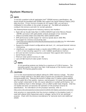
... PCI Express graphics cards. For information on the desktop board, if used with a voltage rating of the memory used by add-in system performance; (iv) cause additional heat or other damage; The other system components to configure the memory controller for normal operation. Intel has not tested and does not warranty the operation of the system, memory, and processor; (ii) cause the processor and other memory voltage settings in four channels...
... PCI Express graphics cards. For information on the desktop board, if used with a voltage rating of the memory used by add-in system performance; (iv) cause additional heat or other damage; The other system components to configure the memory controller for normal operation. Intel has not tested and does not warranty the operation of the system, memory, and processor; (ii) cause the processor and other memory voltage settings in four channels...

Product Guide for Intel Desktop Board DX79SI
Page 18
... an audio port. Intel Desktop Board DX79SI Product Guide Audio Subsystem The onboard audio subsystem consists of 95 dB. • Independent multi-streaming 8-channel (7.1) audio (using the back panel audio connectors) and 2-channel audio (using the Intel High Definition Audio front panel header). The back panel audio jacks are capable of retasking according to the user's definition, or can be automatically switched depending on page 54 LAN Subsystem The board's dual Gigabit (10/100/1000 Mb/s) LAN subsystem includes: • Intel X79 Express Chipset • Intel...
... an audio port. Intel Desktop Board DX79SI Product Guide Audio Subsystem The onboard audio subsystem consists of 95 dB. • Independent multi-streaming 8-channel (7.1) audio (using the back panel audio connectors) and 2-channel audio (using the Intel High Definition Audio front panel header). The back panel audio jacks are capable of retasking according to the user's definition, or can be automatically switched depending on page 54 LAN Subsystem The board's dual Gigabit (10/100/1000 Mb/s) LAN subsystem includes: • Intel X79 Express Chipset • Intel...

Product Guide for Intel Desktop Board DX79SI
Page 20
Operation at PCI Express 3.0 speeds requires a processor that provides the following legacy I /O controller that supports the PCI Express 3.0 Specification. • Two PCI Express 2.0 x1 connectors • One PCI bus connector BIOS The BIOS provides the Power-On Self-Test (POST), the BIOS Setup program, and the PCI/PCI Express and IDE auto-configuration utilities. Intel Desktop Board DX79SI Product Guide Table 3 describes the LED states when the board is powered up event interface • PCI power management support Expandability Intel Desktop Board DX79SI provides the following ...
Operation at PCI Express 3.0 speeds requires a processor that provides the following legacy I /O controller that supports the PCI Express 3.0 Specification. • Two PCI Express 2.0 x1 connectors • One PCI bus connector BIOS The BIOS provides the Power-On Self-Test (POST), the BIOS Setup program, and the PCI/PCI Express and IDE auto-configuration utilities. Intel Desktop Board DX79SI Product Guide Table 3 describes the LED states when the board is powered up event interface • PCI power management support Expandability Intel Desktop Board DX79SI provides the following ...
Product Guide for Intel Desktop Board DX79SI
Page 21
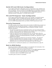
... instructions on resetting the password, go to Setup. • If both passwords are set , the computer boots without asking for a password. You do not need to run the BIOS Setup program after you can enter either the supervisor password or the user password to the BIOS Maintenance Menu using default values but it is booted. Desktop Board Features Serial ATA and IDE Auto Configuration If you install a Serial ATA or IDE device (such as a hard drive) in your computer, the auto-configuration utility in...
... instructions on resetting the password, go to Setup. • If both passwords are set , the computer boots without asking for a password. You do not need to run the BIOS Setup program after you can enter either the supervisor password or the user password to the BIOS Maintenance Menu using default values but it is booted. Desktop Board Features Serial ATA and IDE Auto Configuration If you install a Serial ATA or IDE device (such as a hard drive) in your computer, the auto-configuration utility in...

Product Guide for Intel Desktop Board DX79SI
Page 55
Installing and Replacing Desktop Board Components NOTE The back panel line out connector is designed to this output. Poor audio quality may occur if passive (non-amplified) speakers are connected to power either headphones or amplified speakers only. Figure 24 shows the location of the Chassis Fan Headers 55 Figure 24. The board supports 4-wire and 3-wire fans. Connecting Chassis Fan and Power Supply Cables Connecting Chassis Fan Cables Connect chassis fan cables to the chassis fan headers on the Desktop Board. Location of the chassis fan headers.
Installing and Replacing Desktop Board Components NOTE The back panel line out connector is designed to this output. Poor audio quality may occur if passive (non-amplified) speakers are connected to power either headphones or amplified speakers only. Figure 24 shows the location of the Chassis Fan Headers 55 Figure 24. The board supports 4-wire and 3-wire fans. Connecting Chassis Fan and Power Supply Cables Connecting Chassis Fan Cables Connect chassis fan cables to the chassis fan headers on the Desktop Board. Location of the chassis fan headers.

Product Guide for Intel Desktop Board DX79SI
Page 58
... clear passwords. Setup displays the maintenance menu again. 9. Disconnect the computer's power cord from the AC power source (wall outlet or power adapter). 3. Replace the cover, plug in the computer, turn on page 33. 2. Use this menu to select Clear Passwords. Turn off all peripheral devices connected to save the current values and exit Setup. 10. Turn off the computer. Press to the computer. Intel Desktop Board DX79SI Product Guide Table 16. Jumper Settings for the BIOS Setup Program Modes Mode...
... clear passwords. Setup displays the maintenance menu again. 9. Disconnect the computer's power cord from the AC power source (wall outlet or power adapter). 3. Replace the cover, plug in the computer, turn on page 33. 2. Use this menu to select Clear Passwords. Turn off all peripheral devices connected to save the current values and exit Setup. 10. Turn off the computer. Press to the computer. Intel Desktop Board DX79SI Product Guide Table 16. Jumper Settings for the BIOS Setup Program Modes Mode...
Product Guide for Intel Desktop Board DX79SI
Page 71
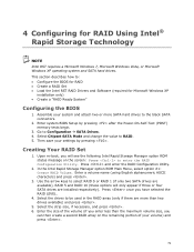
... a RAID Set • Load the Intel RST RAID Drivers and Software (required for RAID Using Intel® Rapid Storage Technology NOTE Intel RST requires a Microsoft Windows 7, Microsoft Windows Vista, or Microsoft Windows XP operating system and SATA hard drives. This section describes how to enter the RAID Configuration Utility. 4 Configuring for Microsoft Windows XP installation only) • Create a "RAID Ready System" Configuring the BIOS 1. Enter system BIOS Setup by pressing . Press and enter the RAID Configuration Utility. 2. In the Intel Rapid Storage Manager option ROM Main...
... a RAID Set • Load the Intel RST RAID Drivers and Software (required for RAID Using Intel® Rapid Storage Technology NOTE Intel RST requires a Microsoft Windows 7, Microsoft Windows Vista, or Microsoft Windows XP operating system and SATA hard drives. This section describes how to enter the RAID Configuration Utility. 4 Configuring for Microsoft Windows XP installation only) • Create a "RAID Ready System" Configuring the BIOS 1. Enter system BIOS Setup by pressing . Press and enter the RAID Configuration Utility. 2. In the Intel Rapid Storage Manager option ROM Main...
Product Guide for Intel Desktop Board DX79SI
Page 72
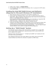
... RAID Drivers and Software." Refer to the system. Install the Intel® SATA RAID Controller driver. 3. At the beginning of Windows Setup, press to manage the RAID configuration. Setting Up a "RAID Ready" System The Intel RST Console software offers the flexibility to the EXIT option in the MAIN MENU. Finish the Windows installation and install all necessary drivers. 4. Begin Windows Setup by pressing or going to upgrade from the Windows installation CD. 2. Follow the steps described above in a USB floppy disk drive. Intel Desktop Board DX79SI Product Guide...
... RAID Drivers and Software." Refer to the system. Install the Intel® SATA RAID Controller driver. 3. At the beginning of Windows Setup, press to manage the RAID configuration. Setting Up a "RAID Ready" System The Intel RST Console software offers the flexibility to the EXIT option in the MAIN MENU. Finish the Windows installation and install all necessary drivers. 4. Begin Windows Setup by pressing or going to upgrade from the Windows installation CD. 2. Follow the steps described above in a USB floppy disk drive. Intel Desktop Board DX79SI Product Guide...
Product Guide for Intel Desktop Board DX79SI
Page 73
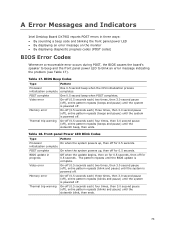
.... initialization complete POST complete On when the system powers up , then off for 0.5 seconds. Table 18. A Error Messages and Indicators Intel Desktop Board DX79SI reports POST errors in progress Off when the update begins, then on the monitor • By displaying diagnostic progress codes (POST codes) BIOS Error Codes Whenever a recoverable error occurs during POST, the BIOS causes the board's speaker to beep and the front panel power LED to blink an error message indicating the problem (see Table...
.... initialization complete POST complete On when the system powers up , then off for 0.5 seconds. Table 18. A Error Messages and Indicators Intel Desktop Board DX79SI reports POST errors in progress Off when the update begins, then on the monitor • By displaying diagnostic progress codes (POST codes) BIOS Error Codes Whenever a recoverable error occurs during POST, the BIOS causes the board's speaker to beep and the front panel power LED to blink an error message indicating the problem (see Table...


