

Product Specification
Page 10
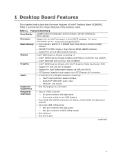
...sockets • Support for DDR2 800, DDR2 667, or DDR2 533 MHz DIMMs • Support for up to 8 GB of system memory using DDR2 667 or DDR2 533 DIMMs • Support for up to 4 GB of system memory using DDR2 800 DIMMs Intel® Q965 Express Chipset, consisting of the Desktop Board DQ965WC. Intel... Desktop Board DQ965WC Technical Product Specification 1.1 Overview 1.1.1 Feature Summary Table 1 summarizes the major features of : •...
...sockets • Support for DDR2 800, DDR2 667, or DDR2 533 MHz DIMMs • Support for up to 8 GB of system memory using DDR2 667 or DDR2 533 DIMMs • Support for up to 4 GB of system memory using DDR2 800 DIMMs Intel® Q965 Express Chipset, consisting of the Desktop Board DQ965WC. Intel... Desktop Board DQ965WC Technical Product Specification 1.1 Overview 1.1.1 Feature Summary Table 1 summarizes the major features of : •...

Product Specification
Page 14
... Connector LGA775 Processor Socket System Bus (1066/800/533 MHz) PCI Express x16 Connector PCI Express x16 Interface Display Interface VGA Port Intel Q965 Express Chipset Intel 82Q965 Graphics and Memory Controller Hub (GMCH) PCI Express x1 Interface LPC Bus USB Intel 82801HO I/O Controller Hub...Connectors (4) Audio Codec Mic In Line Out Line In/Retasking Jack Line Out/Retasking Jack Mic In/Retasking Jack Figure 2. Intel Desktop Board DQ965WC Technical Product Specification 1.1.3 Block Diagram Figure 2 is a block diagram of the major functional areas. Block Diagram High Definition ...
... Connector LGA775 Processor Socket System Bus (1066/800/533 MHz) PCI Express x16 Connector PCI Express x16 Interface Display Interface VGA Port Intel Q965 Express Chipset Intel 82Q965 Graphics and Memory Controller Hub (GMCH) PCI Express x1 Interface LPC Bus USB Intel 82801HO I/O Controller Hub...Connectors (4) Audio Codec Mic In Line Out Line In/Retasking Jack Line Out/Retasking Jack Mic In/Retasking Jack Figure 2. Intel Desktop Board DQ965WC Technical Product Specification 1.1.3 Block Diagram Figure 2 is a block diagram of the major functional areas. Block Diagram High Definition ...

Product Specification
Page 15
...of supported processors. Supported processors Refer to Section 2.7.2.2, page 57 15 Intel® Desktop Board DQ965WC under "Desktop Board Products" or "Desktop Board Support" Available configurations for the Desktop Board DQ965WC Processor data sheets ICH8DO addressing Audio software and utilities LAN software and drivers...: • Intel Core 2 Duo processor in an LGA775 socket with a 1066 or 800 MHz system bus • Intel Pentium D processor in an LGA775 processor socket with an 800 or 533 MHz system bus • Intel Pentium 4 processor in an LGA775 processor socket with an 800...
...of supported processors. Supported processors Refer to Section 2.7.2.2, page 57 15 Intel® Desktop Board DQ965WC under "Desktop Board Products" or "Desktop Board Support" Available configurations for the Desktop Board DQ965WC Processor data sheets ICH8DO addressing Audio software and utilities LAN software and drivers...: • Intel Core 2 Duo processor in an LGA775 socket with a 1066 or 800 MHz system bus • Intel Pentium D processor in an LGA775 processor socket with an 800 or 533 MHz system bus • Intel Pentium 4 processor in an LGA775 processor socket with an 800...

Product Specification
Page 16
Table 3 lists the supported DIMM configurations. Intel Desktop Board DQ965WC Technical Product Specification 1.4 System Memory The board has four DIMM sockets and supports the following memory features: • 1.8 V (only) DDR2 SDRAM DIMMs with gold-plated contacts • Unbuffered, single-sided or double-sided DIMMs with the ...
Table 3 lists the supported DIMM configurations. Intel Desktop Board DQ965WC Technical Product Specification 1.4 System Memory The board has four DIMM sockets and supports the following memory features: • 1.8 V (only) DDR2 SDRAM DIMMs with gold-plated contacts • Unbuffered, single-sided or double-sided DIMMs with the ...

Product Specification
Page 18
...channels. Technology and device width can vary from one channel to dual channel operation; NOTE The DIMM0 sockets of both channels are black. The DIMM1 sockets of both channels are blue. Memory Channel Configuration and DIMM Configuration # INTEGRATOR'S NOTE Regardless of the ...memory (the memory that is lowest within the system memory map) is mapped to the other . Intel Desktop Board DQ965WC Technical Product Specification 1.4.1 Memory Configurations The Intel 82Q965 GMCH supports the following types of DRAM memory. This is installed or the memory capacities are ...
...channels. Technology and device width can vary from one channel to dual channel operation; NOTE The DIMM0 sockets of both channels are black. The DIMM1 sockets of both channels are blue. Memory Channel Configuration and DIMM Configuration # INTEGRATOR'S NOTE Regardless of the ...memory (the memory that is lowest within the system memory map) is mapped to the other . Intel Desktop Board DQ965WC Technical Product Specification 1.4.1 Memory Configurations The Intel 82Q965 GMCH supports the following types of DRAM memory. This is installed or the memory capacities are ...

Product Specification
Page 19
... two DIMMs. In this example, the combined capacity of the two DIMMs in Channel A equal the capacity of the single DIMM in the DIMM0 (blue) socket of both channels are populated with Three DIMMs 19 Product Description 1.4.1.1 Dual Channel (Interleaved) Mode Configurations Figure 4 shows a dual channel configuration using three DIMMs. In...
... two DIMMs. In this example, the combined capacity of the two DIMMs in Channel A equal the capacity of the single DIMM in the DIMM0 (blue) socket of both channels are populated with Three DIMMs 19 Product Description 1.4.1.1 Dual Channel (Interleaved) Mode Configurations Figure 4 shows a dual channel configuration using three DIMMs. In...

Product Specification
Page 21
...Single Channel (Asymmetric) Mode Configuration with Three DIMMs 21 Figure 7 shows a single channel configuration using three DIMMs. In this example, only the DIMM0 (blue) socket of Channel B. 256 MB 512 MB 512 MB Channel A, DIMM 0 Channel A, DIMM 1 Channel B, DIMM 0 Channel B, DIMM 1 OM18361 Figure 8. ...In this example, the combined capacity of the two DIMMs in Channel A does not equal the capacity of the single DIMM in the DIMM0 (blue) socket of Channel A is not populated. 512 MB Channel A, DIMM 0 Channel A, DIMM 1 Channel B, DIMM 0 Channel B, DIMM 1 OM18360 Figure 7. Single...
...Single Channel (Asymmetric) Mode Configuration with Three DIMMs 21 Figure 7 shows a single channel configuration using three DIMMs. In this example, only the DIMM0 (blue) socket of Channel B. 256 MB 512 MB 512 MB Channel A, DIMM 0 Channel A, DIMM 1 Channel B, DIMM 0 Channel B, DIMM 1 OM18361 Figure 8. ...In this example, the combined capacity of the two DIMMs in Channel A does not equal the capacity of the single DIMM in the DIMM0 (blue) socket of Channel A is not populated. 512 MB Channel A, DIMM 0 Channel A, DIMM 1 Channel B, DIMM 0 Channel B, DIMM 1 OM18360 Figure 7. Single...

Product Specification
Page 22
...DIMMs. The operation is as follows: • The 512 MB DIMM in the Channel A, DIMM 0 socket and the lower 512 MB of the DIMM in the Channel B, DIMM 0 socket operate together in dual channel mode. • The remaining (upper) 512 MB of flex mode requires DIMMs... to be installed in single channel mode. 512 MB 1 GB Channel A, DIMM 0 Channel A, DIMM 1 Channel B, DIMM 0 Channel B, DIMM 1 Figure 9. Intel Desktop Board DQ965WC Technical Product Specification 1.4.1.3 ...
...DIMMs. The operation is as follows: • The 512 MB DIMM in the Channel A, DIMM 0 socket and the lower 512 MB of the DIMM in the Channel B, DIMM 0 socket operate together in dual channel mode. • The remaining (upper) 512 MB of flex mode requires DIMMs... to be installed in single channel mode. 512 MB 1 GB Channel A, DIMM 0 Channel A, DIMM 1 Channel B, DIMM 0 Channel B, DIMM 1 Figure 9. Intel Desktop Board DQ965WC Technical Product Specification 1.4.1.3 ...

Product Specification
Page 29
... striping and mirroring • RAID 5 - When the computer is plugged in CMOS RAM (for example, the date and time) might not be loaded into a wall socket, the battery has an estimated life of the battery. 29 data mirroring • RAID 0+1 (or RAID 10) - When the voltage drops below a certain level, the...
... striping and mirroring • RAID 5 - When the computer is plugged in CMOS RAM (for example, the date and time) might not be loaded into a wall socket, the battery has an estimated life of the battery. 29 data mirroring • RAID 0+1 (or RAID 10) - When the voltage drops below a certain level, the...

English Product Guide
Page 7
...39 19. Removing a PCI Express x16 Card 44 23. Internal Headers 46 25. Back Panel Connectors 55 30. SATA Port Mapping for Desktop Board DQ965WC 65 32. LAN Connector LEDs 18 3. Installing a PCI Express x16 Card 43 22. Back Panel Audio Connectors 50 26. Installing the I/O Shield... 24. Use Care Routing the Thermal Module Fan Cable 36 14. Desktop Board DQ965WC Mounting Screw Hole Locations 31 6. Installing a DIMM 41 21. Location of the On-board Power Indicators 25 4. Lift Socket Lever 32 7. Connecting Power Supply Cables 52 28. Connect the Thermal Module Fan...
...39 19. Removing a PCI Express x16 Card 44 23. Internal Headers 46 25. Back Panel Connectors 55 30. SATA Port Mapping for Desktop Board DQ965WC 65 32. LAN Connector LEDs 18 3. Installing a PCI Express x16 Card 43 22. Back Panel Audio Connectors 50 26. Installing the I/O Shield... 24. Use Care Routing the Thermal Module Fan Cable 36 14. Desktop Board DQ965WC Mounting Screw Hole Locations 31 6. Installing a DIMM 41 21. Location of the On-board Power Indicators 25 4. Lift Socket Lever 32 7. Connecting Power Supply Cables 52 28. Connect the Thermal Module Fan...
English Product Guide
Page 9
...the desktop board. Table 1 summarizes the major features of Intel® Desktop Board DQ965WC. Table 1. For more information, go to: www.intel.com/go/FindCPU • Four 240-pin, DDR2 1.8 V SDRAM Dual Inline Memory Module (DIMM) sockets • 800/667/533 MHz single or dual channel DDR2...VGA and DVI-D • PCI Express* graphics card support via a PCI Express x16 connector • 6-channel (5.1) onboard subsystem, featuring: ― Intel® High Definition Audio interface ― SigmaTel* STAC9227 audio codec ― HD Audio Link header • One PCI Express x16 connector •...
...the desktop board. Table 1 summarizes the major features of Intel® Desktop Board DQ965WC. Table 1. For more information, go to: www.intel.com/go/FindCPU • Four 240-pin, DDR2 1.8 V SDRAM Dual Inline Memory Module (DIMM) sockets • 800/667/533 MHz single or dual channel DDR2...VGA and DVI-D • PCI Express* graphics card support via a PCI Express x16 connector • 6-channel (5.1) onboard subsystem, featuring: ― Intel® High Definition Audio interface ― SigmaTel* STAC9227 audio codec ― HD Audio Link header • One PCI Express x16 connector •...
English Product Guide
Page 12
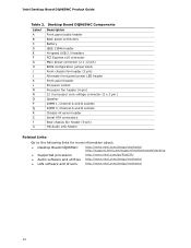
... (2 x 2 pin ) Speaker DIMM 1, Channel A and B sockets DIMM 0, Channel A and B sockets Chassis intrusion header Serial ATA connectors Rear chassis fan header (3-pin) HD Audio Link header Related Links: Go to the following links for more information about: • Desktop Board DQ965WC http://www.intel.com/design/motherbd http://support.intel.com/support/motherboards/desktop • Supported...
... (2 x 2 pin ) Speaker DIMM 1, Channel A and B sockets DIMM 0, Channel A and B sockets Chassis intrusion header Serial ATA connectors Rear chassis fan header (3-pin) HD Audio Link header Related Links: Go to the following links for more information about: • Desktop Board DQ965WC http://www.intel.com/design/motherbd http://support.intel.com/support/motherboards/desktop • Supported...
English Product Guide
Page 13
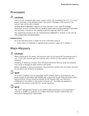
...board may result in damage to the board or the system may result in damage to both memory and board. Desktop Board DQ965WC supports an Intel processor in order for more information about: • Instructions on installing or upgrading the processor, page 32 in Chapter 2 Main.... Desktop Board Features Processor CAUTION Failure to use . The processor connects to the desktop board through the LGA775 socket. NOTE To be fully compliant with all applicable Intel® SDRAM memory specifications, the board should be populated with the desktop board and must be populated in Channel...
...board may result in damage to the board or the system may result in damage to both memory and board. Desktop Board DQ965WC supports an Intel processor in order for more information about: • Instructions on installing or upgrading the processor, page 32 in Chapter 2 Main.... Desktop Board Features Processor CAUTION Failure to use . The processor connects to the desktop board through the LGA775 socket. NOTE To be fully compliant with all applicable Intel® SDRAM memory specifications, the board should be populated with the desktop board and must be populated in Channel...

English Product Guide
Page 22
... is designed to enhance platform security above and below acceptable values • Intel Quiet System Technology, delivering acoustically-optimized thermal management NOTE Memory must be installed in the Channel A, DIMM 0 socket to the chassis intrusion header on page 46 for the location of today...• Thermally monitored closed-loop fan control, for all onboard fans, that detects if the chassis cover has been removed. Intel Desktop Board DQ965WC Product Guide Trusted Platform Module (TPM) The TPM 1.2 component is specifically designed to be compatible with the Wired for Management ...
... is designed to enhance platform security above and below acceptable values • Intel Quiet System Technology, delivering acoustically-optimized thermal management NOTE Memory must be installed in the Channel A, DIMM 0 socket to the chassis intrusion header on page 46 for the location of today...• Thermally monitored closed-loop fan control, for all onboard fans, that detects if the chassis cover has been removed. Intel Desktop Board DQ965WC Product Guide Trusted Platform Module (TPM) The TPM 1.2 component is specifically designed to be compatible with the Wired for Management ...

English Product Guide
Page 32
... power has been removed by pushing the lever down and away from the computer; Intel Desktop Board DQ965WC Product Guide Installing and Removing a Processor Instructions on how to do so could damage the processor and the board. Lift Socket Lever 32 the standby power LED should not be lit (see Figure 3 on the...
... power has been removed by pushing the lever down and away from the computer; Intel Desktop Board DQ965WC Product Guide Installing and Removing a Processor Instructions on how to do so could damage the processor and the board. Lift Socket Lever 32 the standby power LED should not be lit (see Figure 3 on the...

English Product Guide
Page 33
Lift the Load Plate 4. Always replace the socket cover if the processor is removed from the load plate (see Figure 8). Remove the Protective Socket Cover 33 Installing and Replacing Desktop Board Components 3. Figure 7. Do not touch the socket contacts (Figure 7, B). Lift the load plate (Figure 7, A). Figure 8. Remove the plastic protective socket cover from the socket. Do not discard the protective socket cover.
Lift the Load Plate 4. Always replace the socket cover if the processor is removed from the load plate (see Figure 8). Remove the Protective Socket Cover 33 Installing and Replacing Desktop Board Components 3. Figure 7. Do not touch the socket contacts (Figure 7, B). Lift the load plate (Figure 7, A). Figure 8. Remove the plastic protective socket cover from the socket. Do not discard the protective socket cover.

English Product Guide
Page 34
...only at the edges, being careful not to the socket cutouts (Figure 10, A). Remove the Processor from the socket. Intel Desktop Board DQ965WC Product Guide 5. Align notches (Figure 10, B) with your thumb and index fingers oriented as shown in the socket. Figure 10. Lower the processor straight down without ...not discard the protective processor cover. Figure 9. Remove the processor from the protective processor cover. Hold the processor with the socket (Figure 10, C). Make sure fingers align to touch the bottom of the processor (see Figure 9). Install the Processor 34
...only at the edges, being careful not to the socket cutouts (Figure 10, A). Remove the Processor from the socket. Intel Desktop Board DQ965WC Product Guide 5. Align notches (Figure 10, B) with your thumb and index fingers oriented as shown in the socket. Figure 10. Lower the processor straight down without ...not discard the protective processor cover. Figure 9. Remove the processor from the protective processor cover. Hold the processor with the socket (Figure 10, C). Make sure fingers align to touch the bottom of the processor (see Figure 9). Install the Processor 34
English Product Guide
Page 35
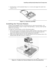
With the BTX Support and Retention Module (SRM) installed in Figure 12. Close the Load Plate Installing the Thermal Module Desktop board DQ965WC has four mounting holes for your chassis. Position the Thermal Module Over the Mounting Holes 35 Installing and Replacing Desktop Board Components 7. To install... in the desktop board and SRM as shown in the chassis, position the Thermal Module on the load plate (Figure 11, A) close and engage the socket lever (Figure 11, B). Figure 11. The board will accept either a Type I or Type II Thermal Module. Align the four captive screws in the ...
With the BTX Support and Retention Module (SRM) installed in Figure 12. Close the Load Plate Installing the Thermal Module Desktop board DQ965WC has four mounting holes for your chassis. Position the Thermal Module Over the Mounting Holes 35 Installing and Replacing Desktop Board Components 7. To install... in the desktop board and SRM as shown in the chassis, position the Thermal Module on the load plate (Figure 11, A) close and engage the socket lever (Figure 11, B). Figure 11. The board will accept either a Type I or Type II Thermal Module. Align the four captive screws in the ...

English Product Guide
Page 38
...to go off before proceeding. You can access the PC Serial Presence Detect Specification at: http://www.intel.com/technology/memory/ddr/specs/dda18c32_64_128x72ag_a.pdf Desktop Board DQ965WC has four 240-pin DDR2 DIMM sockets arranged as DIMM 0 and DIMM 1 in damage to both Channel A and Channel B. NOTE ...The Intel® Management Engine in the chipset requires memory to be lit if the memory slots are ...
...to go off before proceeding. You can access the PC Serial Presence Detect Specification at: http://www.intel.com/technology/memory/ddr/specs/dda18c32_64_128x72ag_a.pdf Desktop Board DQ965WC has four 240-pin DDR2 DIMM sockets arranged as DIMM 0 and DIMM 1 in damage to both Channel A and Channel B. NOTE ...The Intel® Management Engine in the chipset requires memory to be lit if the memory slots are ...

English Product Guide
Page 41
... Memory must be installed in the Channel A, DIMM 0 socket to the computer. Turn off the computer and disconnect the AC power cord. 3. Turn off all peripheral devices connected to enable Intel Quiet System Technology and Intel Active Management Technology. Observe the precautions in "Before You ...Begin" on the top edge of the DIMM socket(s) are firmly in place. 9. Holding the DIMM by the edges, ...
... Memory must be installed in the Channel A, DIMM 0 socket to the computer. Turn off the computer and disconnect the AC power cord. 3. Turn off all peripheral devices connected to enable Intel Quiet System Technology and Intel Active Management Technology. Observe the precautions in "Before You ...Begin" on the top edge of the DIMM socket(s) are firmly in place. 9. Holding the DIMM by the edges, ...

