
DQ965CO Technical Product Specification
Page 7
... Connectors 69 23. Dual Channel (Interleaved) Mode Configuration with Two DIMMs 24 10. Back Panel Connectors 57 16. Connection Diagram for Boards without PS/2 Connectors 70 24. Board Dimensions 68 22. Thermal Sensors and Fan Headers 40 13. Location of the Onboard Power Indicator LEDs 47 14. Memory Channel Configuration and DIMM Configuration 20 4. Location of the Jumper Block 67 21. Contents 4 Error Messages and Beep Codes 4.1 Speaker 85 4.2 BIOS Beep Codes 85 4.3 BIOS Error Messages 85 4.4 Port 80h POST Codes 86 5 Regulatory Compliance and Battery Disposal...
... Connectors 69 23. Dual Channel (Interleaved) Mode Configuration with Two DIMMs 24 10. Back Panel Connectors 57 16. Connection Diagram for Boards without PS/2 Connectors 70 24. Board Dimensions 68 22. Thermal Sensors and Fan Headers 40 13. Location of the Onboard Power Indicator LEDs 47 14. Memory Channel Configuration and DIMM Configuration 20 4. Location of the Jumper Block 67 21. Contents 4 Error Messages and Beep Codes 4.1 Speaker 85 4.2 BIOS Beep Codes 85 4.3 BIOS Error Messages 85 4.4 Port 80h POST Codes 86 5 Regulatory Compliance and Battery Disposal...

DQ965CO Technical Product Specification
Page 8
... Front Panel Power LED Header 65 33. Manufacturing Options 13 3. Main Power Connector 63 29. Intel Desktop Board DQ965CO Technical Product Specification Tables 1. Board Components Shown in Figure 16 59 19. Feature Summary 12 2. Interrupts 54 17. Front and Rear Chassis Fan Headers 61 25. Acceptable Drives/Media Types for a Two-Color Power LED 65 32. DMA Channels 51 14. High Definition Audio Link Header 60 20. System Memory Map 51 13. States for BIOS Recovery 81 41. Boot Device Menu Options...
... Front Panel Power LED Header 65 33. Manufacturing Options 13 3. Main Power Connector 63 29. Intel Desktop Board DQ965CO Technical Product Specification Tables 1. Board Components Shown in Figure 16 59 19. Feature Summary 12 2. Interrupts 54 17. Front and Rear Chassis Fan Headers 61 25. Acceptable Drives/Media Types for a Two-Color Power LED 65 32. DMA Channels 51 14. High Definition Audio Link Header 60 20. System Memory Map 51 13. States for BIOS Recovery 81 41. Boot Device Menu Options...

DQ965CO Technical Product Specification
Page 16
...Chipset Intel 82Q965 Graphics and Memory Controller Hub (GMCH) DVI Port Channel A DIMMs (2) Channel B DIMMs (2) Dual-Channel Memory Bus SMBus DMI Interconnect Gigabit Ethernet Controller LAN Connector USB Back Panel/Front Panel USB Ports Legacy I/O Controller Serial Port Parallel Port PS/2 Mouse* PS/2 Keyboard* LPC Bus Diskette Drive Connector Intel 82801HO I/O Controller Hub (ICH8DO) Serial Peripheral Interface (SPI) Flash Device LPC Bus TPM Component Serial ATA IDE Interface Serial ATA IDE Connectors (6) High Definition Audio Link IEEE-1394a Connector/Header PCI Slot 1 PCI...
...Chipset Intel 82Q965 Graphics and Memory Controller Hub (GMCH) DVI Port Channel A DIMMs (2) Channel B DIMMs (2) Dual-Channel Memory Bus SMBus DMI Interconnect Gigabit Ethernet Controller LAN Connector USB Back Panel/Front Panel USB Ports Legacy I/O Controller Serial Port Parallel Port PS/2 Mouse* PS/2 Keyboard* LPC Bus Diskette Drive Connector Intel 82801HO I/O Controller Hub (ICH8DO) Serial Peripheral Interface (SPI) Flash Device LPC Bus TPM Component Serial ATA IDE Interface Serial ATA IDE Connectors (6) High Definition Audio Link IEEE-1394a Connector/Header PCI Slot 1 PCI...
DQ965CO Technical Product Specification
Page 18
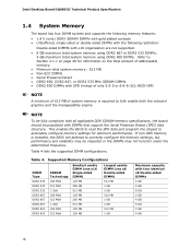
...GB 4 GB 8 GB 2 GB 4 GB 18 Intel Desktop Board DQ965CO Technical Product Specification 1.4 System Memory The board has four DIMM sockets and supports the following memory features: • 1.8 V (only) DDR2 SDRAM ...lists the supported DIMM configurations. Table 4. This enables the BIOS to read the SPD data and program the chipset to correctly configure the memory settings, but performance and reliability may be populated with DIMMs that support the Serial Presence Detect (SPD) data structure. NOTE To be fully compliant with all applicable DDR SDRAM memory specifications, the board...
...GB 4 GB 8 GB 2 GB 4 GB 18 Intel Desktop Board DQ965CO Technical Product Specification 1.4 System Memory The board has four DIMM sockets and supports the following memory features: • 1.8 V (only) DDR2 SDRAM ...lists the supported DIMM configurations. Table 4. This enables the BIOS to read the SPD data and program the chipset to correctly configure the memory settings, but performance and reliability may be populated with DIMMs that support the Serial Presence Detect (SPD) data structure. NOTE To be fully compliant with all applicable DDR SDRAM memory specifications, the board...

DQ965CO Technical Product Specification
Page 29
... Intel GMA 3000 graphics controller is enabled and the PCI Express x16 connector is 1600 x 1200 at 60 Hz. The maximum supported resolution is configured for SDVO mode. SDVO mode enables the SDVO ports to the PCI Express x16 connector. NOTE The use of DVMT requires operating system driver support. 1.7.1.3 Configuration Modes A list of driving up to a 400 MHz pixel clock. DVI Port Status Conditions PCI Express x16 connector status No add-in card installed Non-video PCI Express x1 add-in card installed PCI Express x4...
... Intel GMA 3000 graphics controller is enabled and the PCI Express x16 connector is 1600 x 1200 at 60 Hz. The maximum supported resolution is configured for SDVO mode. SDVO mode enables the SDVO ports to the PCI Express x16 connector. NOTE The use of DVMT requires operating system driver support. 1.7.1.3 Configuration Modes A list of driving up to a 400 MHz pixel clock. DVI Port Status Conditions PCI Express x16 connector status No add-in card installed Non-video PCI Express x1 add-in card installed PCI Express x4...
DQ965CO Technical Product Specification
Page 31
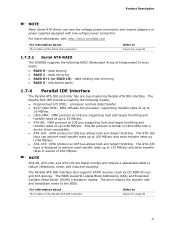
... The location of Independent Drives) levels: • RAID 0 - data mirroring • RAID 0+1 (or RAID 10) - The Parallel ATA IDE interface supports the following RAID (Redundant Array of the Parallel ATA IDE connector Refer to 88 MB/sec. • ATA-133: DMA protocol on IDE bus allows host and target throttling. Product Description NOTE Many Serial ATA drives use new low-voltage power connectors and require adaptors or power supplies equipped...
... The location of Independent Drives) levels: • RAID 0 - data mirroring • RAID 0+1 (or RAID 10) - The Parallel ATA IDE interface supports the following RAID (Redundant Array of the Parallel ATA IDE connector Refer to 88 MB/sec. • ATA-133: DMA protocol on IDE bus allows host and target throttling. Product Description NOTE Many Serial ATA drives use new low-voltage power connectors and require adaptors or power supplies equipped...
DQ965CO Technical Product Specification
Page 50
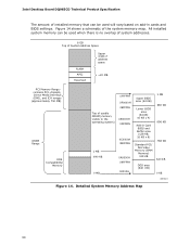
...-in cards and BIOS settings. All installed system memory can be used will vary based on add-in Card BIOS and Buffer area (128 KB; 16 KB x 8) Standard PCI/ ISA Video Memory (SMM Memory) 128 KB DOS area (640 KB) 1 MB 960 KB 896 KB 768 KB 640 KB 0 KB OM18311 Figure 14. Intel Desktop Board DQ965CO Technical Product Specification The amount of installed memory that can be used when...
...-in cards and BIOS settings. All installed system memory can be used will vary based on add-in Card BIOS and Buffer area (128 KB; 16 KB x 8) Standard PCI/ ISA Video Memory (SMM Memory) 128 KB DOS area (640 KB) 1 MB 960 KB 896 KB 768 KB 640 KB 0 KB OM18311 Figure 14. Intel Desktop Board DQ965CO Technical Product Specification The amount of installed memory that can be used when...
DQ965CO Technical Product Specification
Page 77
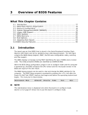
... the Serial Peripheral Interface Flash Memory (SPI Flash) and can be updated using a disk-based program. The initial production BIOSs are identified as CO96510J.86A. The BIOS Setup program can be used to view and change the BIOS settings for the computer. The SPI Flash contains the BIOS Setup program, POST, the PCI auto-configuration utility, and Plug and Play support. 3 Overview of BIOS and a revision code. Maintenance Main Advanced Security Power Boot Exit NOTE The maintenance menu is displayed...
... the Serial Peripheral Interface Flash Memory (SPI Flash) and can be updated using a disk-based program. The initial production BIOSs are identified as CO96510J.86A. The BIOS Setup program can be used to view and change the BIOS settings for the computer. The SPI Flash contains the BIOS Setup program, POST, the PCI auto-configuration utility, and Plug and Play support. 3 Overview of BIOS and a revision code. Maintenance Main Advanced Security Power Boot Exit NOTE The maintenance menu is displayed...
DQ965CO Technical Product Specification
Page 78
... Load the default configuration values for menu screens. BIOS Setup Program Menu Bar Maintenance Main Advanced Security Clears passwords and displays processor information Displays processor and memory configuration Configures advanced features available through the chipset Sets passwords and security features Power Configures power management features and power supply controls Boot Selects boot options Exit Saves or discards changes to configure the system. Table 38. Table 39. PCI devices may be available for use by the add-in cards. Intel Desktop Board DQ965CO...
... Load the default configuration values for menu screens. BIOS Setup Program Menu Bar Maintenance Main Advanced Security Clears passwords and displays processor information Displays processor and memory configuration Configures advanced features available through the chipset Sets passwords and security features Power Configures power management features and power supply controls Boot Selects boot options Exit Saves or discards changes to configure the system. Table 38. Table 39. PCI devices may be available for use by the add-in cards. Intel Desktop Board DQ965CO...
DQ965CO Technical Product Specification
Page 79
... the system types, capabilities, operational status, and installation dates for managing computers in a managed network. Using SMBIOS, a system administrator can override the auto-configuration options by specifying manual configuration in the BIOS Setup program, the BIOS automatically sets up to optimize capacity and performance. The main component of SMBIOS is a Desktop Management Interface (DMI) compliant method for system components. The IDE interface supports hard drives up the PCI IDE connector with independent I/O channel support.
... the system types, capabilities, operational status, and installation dates for managing computers in a managed network. Using SMBIOS, a system administrator can override the auto-configuration options by specifying manual configuration in the BIOS Setup program, the BIOS automatically sets up to optimize capacity and performance. The main component of SMBIOS is a Desktop Management Interface (DMI) compliant method for system components. The IDE interface supports hard drives up the PCI IDE connector with independent I/O channel support.

DQ965CO Technical Product Specification
Page 87
Error Messages and Beep Codes Table 46. Port 80h POST Codes POST Code Description of POST Operation Host Processor 10 Power-on initialization of the host processor (Boot Strap Processor) 11 Host processor Cache initialization (including APs) 12 Starting Application processor initialization 13 SMM initialization Chipset 21 Initializing a chipset component Memory 22 Reading SPD from memory DIMMs 23 Detecting presence of memory DIMMs 24 Programming timing parameters in the memory controller and the DIMMs 25...
Error Messages and Beep Codes Table 46. Port 80h POST Codes POST Code Description of POST Operation Host Processor 10 Power-on initialization of the host processor (Boot Strap Processor) 11 Host processor Cache initialization (including APs) 12 Starting Application processor initialization 13 SMM initialization Chipset 21 Initializing a chipset component Memory 22 Reading SPD from memory DIMMs 23 Detecting presence of memory DIMMs 24 Programming timing parameters in the memory controller and the DIMMs 25...
DQ965CO Technical Product Specification
Page 89
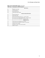
Error Messages and Beep Codes Table 46. Port 80h POST Codes (continued) POST Code Description of POST Operation DXE Drivers E7 Waiting for user input E8 Checking password E9 Entering BIOS setup EB Calling Legacy Option ROMs Runtime Phase/EFI OS Boot F4 Entering Sleep state F5 Exiting Sleep state F8 EFI boot service ExitBootServices ( ) has been called F9 EFI runtime service SetVirtualAddressMap ( ) has been called FA EFI runtime service ResetSystem ( ) has been called PEIMs/Recovery 30 Crisis...
Error Messages and Beep Codes Table 46. Port 80h POST Codes (continued) POST Code Description of POST Operation DXE Drivers E7 Waiting for user input E8 Checking password E9 Entering BIOS setup EB Calling Legacy Option ROMs Runtime Phase/EFI OS Boot F4 Entering Sleep state F5 Exiting Sleep state F8 EFI boot service ExitBootServices ( ) has been called F9 EFI runtime service SetVirtualAddressMap ( ) has been called FA EFI runtime service ResetSystem ( ) has been called PEIMs/Recovery 30 Crisis...
DQ965CO Desktop Board Specification Update
Page 6
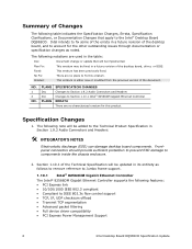
... • Full device driver compatibility • PCI Express Power Management Support 6 Intel Desktop Board DQ965CO Specification Update Plan Fix: This erratum may be implemented. The following notations are used in a future revision of the desktop board, driver, or BIOS. Intel intends to fix this product. Fixed: This erratum has been previously fixed. PLANS Doc Doc PLANS SPECIFICATION CHANGES Changes to Section 1.9.2 Audio Connectors and Headers Changes to Section 1.10.1 Intel® 82566DM Gigabit Ethernet Controller ERRATA There are...
... • Full device driver compatibility • PCI Express Power Management Support 6 Intel Desktop Board DQ965CO Specification Update Plan Fix: This erratum may be implemented. The following notations are used in a future revision of the desktop board, driver, or BIOS. Intel intends to fix this product. Fixed: This erratum has been previously fixed. PLANS Doc Doc PLANS SPECIFICATION CHANGES Changes to Section 1.9.2 Audio Connectors and Headers Changes to Section 1.10.1 Intel® 82566DM Gigabit Ethernet Controller ERRATA There are...
English Product Guide
Page 3
... hardware components 3 Updating the BIOS: instructions on how to update the BIOS 4 Configuring for RAID (Intel® Matrix Storage Technology): information about configuring your system for RAID A Error Messages and Indicators: information about board layout, component installation, BIOS update, and regulatory requirements for Intended Applications All Intel desktop boards are used in homes, offices, schools, computer rooms, and similar locations. It is intended for general audiences. Intended Audience The Product Guide is not intended...
... hardware components 3 Updating the BIOS: instructions on how to update the BIOS 4 Configuring for RAID (Intel® Matrix Storage Technology): information about configuring your system for RAID A Error Messages and Indicators: information about board layout, component installation, BIOS update, and regulatory requirements for Intended Applications All Intel desktop boards are used in homes, offices, schools, computer rooms, and similar locations. It is intended for general audiences. Intended Audience The Product Guide is not intended...
English Product Guide
Page 6
... the BIOS Configuration Jumper 56 Clearing Passwords 58 Back Panel Connectors 59 3 Updating the BIOS Updating the BIOS with the Intel® Express BIOS Update Utility 65 Updating the BIOS with the ISO Image BIOS Update File or the Iflash Memory Update Utility 66 Obtaining the BIOS Update File 66 Updating the BIOS with the ISO Image BIOS Update File 66 Updating the BIOS with Iflash 67 Recovering the BIOS 68 4 Configuring for RAID (Intel® Matrix Storage Technology) Configuring the BIOS for Intel Matrix Storage Technology 69 SATA Port Mapping 69 Creating Your RAID Set 70 Loading...
... the BIOS Configuration Jumper 56 Clearing Passwords 58 Back Panel Connectors 59 3 Updating the BIOS Updating the BIOS with the Intel® Express BIOS Update Utility 65 Updating the BIOS with the ISO Image BIOS Update File or the Iflash Memory Update Utility 66 Obtaining the BIOS Update File 66 Updating the BIOS with the ISO Image BIOS Update File 66 Updating the BIOS with Iflash 67 Recovering the BIOS 68 4 Configuring for RAID (Intel® Matrix Storage Technology) Configuring the BIOS for Intel Matrix Storage Technology 69 SATA Port Mapping 69 Creating Your RAID Set 70 Loading...
English Product Guide
Page 12
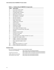
... PCI Express x16 connector PCI Express x1 connector PCI bus connector 1 PCI bus connector 2 IEEE 1394a header Diskette drive connector IDE connector Serial port header Parallel port header Front panel header Front chassis fan header (3-pin) Alternate front panel power LED header Speaker Chassis intrusion header HD Audio Link header Processor socket 12 V processor core voltage connector (2 x 2 pin ) Processor fan header (4-pin) DIMM 1, Channel A and B sockets DIMM 0, Channel A and B sockets Rear chassis fan header (3-pin) Battery Main power connector (2 x 12 pin) BIOS configuration jumper...
... PCI Express x16 connector PCI Express x1 connector PCI bus connector 1 PCI bus connector 2 IEEE 1394a header Diskette drive connector IDE connector Serial port header Parallel port header Front panel header Front chassis fan header (3-pin) Alternate front panel power LED header Speaker Chassis intrusion header HD Audio Link header Processor socket 12 V processor core voltage connector (2 x 2 pin ) Processor fan header (4-pin) DIMM 1, Channel A and B sockets DIMM 0, Channel A and B sockets Rear chassis fan header (3-pin) Battery Main power connector (2 x 12 pin) BIOS configuration jumper...
English Product Guide
Page 21
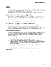
... you install a Serial ATA or IDE device (such as a hard drive) in your computer, the auto-configuration utility in the BIOS Setup program. Security Passwords The BIOS includes security features that add-in card. The password prompt is displayed before the computer is set, pressing at the password prompt of Setup gives the user restricted access to boot the computer. If only the supervisor password is stored in Chapter 3. Desktop Board Features BIOS The BIOS provides the Power...
... you install a Serial ATA or IDE device (such as a hard drive) in your computer, the auto-configuration utility in the BIOS Setup program. Security Passwords The BIOS includes security features that add-in card. The password prompt is displayed before the computer is set, pressing at the password prompt of Setup gives the user restricted access to boot the computer. If only the supervisor password is stored in Chapter 3. Desktop Board Features BIOS The BIOS provides the Power...
English Product Guide
Page 58
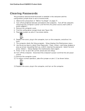
... AC power source. 11. Remove the computer cover. 4. Setup displays the maintenance menu again. 9. Turn off the computer. Replace the cover, plug in "Before You Begin" on pins 1-2 as shown below . 13. The computer starts the Setup program. To restore normal operation, place the jumper on page 27. 2. Find the configuration jumper block (see Figure 30). 5. Intel Desktop Board DQ965CO Product Guide Clearing Passwords This procedure assumes that you confirm clearing the password...
... AC power source. 11. Remove the computer cover. 4. Setup displays the maintenance menu again. 9. Turn off the computer. Replace the cover, plug in "Before You Begin" on pins 1-2 as shown below . 13. The computer starts the Setup program. To restore normal operation, place the jumper on page 27. 2. Find the configuration jumper block (see Figure 30). 5. Intel Desktop Board DQ965CO Product Guide Clearing Passwords This procedure assumes that you confirm clearing the password...
English Product Guide
Page 70
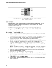
... caution when replacing a failed drive within a RAID storage array. Use the arrow keys to be in Figure 34. However, you can create more than one RAID array on the screen: Press to enter the RAID Configuration Utility. Exit the Option ROM user interface by pressing or going to Create Volume. 8. use the new mapping shown in English alphanumeric ASCII characters. 3. Intel Desktop Board DQ965CO Product Guide Figure 34. Creating Your RAID Set 1. NOTE...
... caution when replacing a failed drive within a RAID storage array. Use the arrow keys to be in Figure 34. However, you can create more than one RAID array on the screen: Press to enter the RAID Configuration Utility. Exit the Option ROM user interface by pressing or going to Create Volume. 8. use the new mapping shown in English alphanumeric ASCII characters. 3. Intel Desktop Board DQ965CO Product Guide Figure 34. Creating Your RAID Set 1. NOTE...
English Product Guide
Page 71
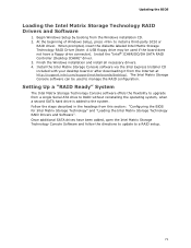
... Intel Express Installer CD included with your desktop board or after downloading it from this section: "Configuring the BIOS for Intel Matrix Storage Technology" and "Loading the Intel Matrix Storage Technology RAID Drivers and Software". Follow the steps described in the headings from the Internet at http://support.intel.com/support/motherboards/desktop/. Updating the BIOS Loading the Intel Matrix Storage Technology RAID Drivers and Software 1. Begin Windows Setup by booting from a single Serial ATA drive to RAID without reinstalling the operating system, when a second SATA hard drive...
... Intel Express Installer CD included with your desktop board or after downloading it from this section: "Configuring the BIOS for Intel Matrix Storage Technology" and "Loading the Intel Matrix Storage Technology RAID Drivers and Software". Follow the steps described in the headings from the Internet at http://support.intel.com/support/motherboards/desktop/. Updating the BIOS Loading the Intel Matrix Storage Technology RAID Drivers and Software 1. Begin Windows Setup by booting from a single Serial ATA drive to RAID without reinstalling the operating system, when a second SATA hard drive...


