
DQ965CO Technical Product Specification
Page 5
...14 1.1.4 Block Diagram 16 1.2 Online Support 17 1.3 Processor 17 1.4 System Memory 18 1.4.1 Memory Configurations 20 1.5 Intel® Virtualization Technology (Intel® VT 25 1.6 Intel® vPro™ Technology Support 26 1.7 Intel® Q965 Express Chipset 27 1.7.1 Intel Q965 Graphics Subsystem 27 1.7.2 USB 30 1.7.3 Serial ...Controller 36 1.10.2 LAN Subsystem Software 36 1.10.3 RJ-45 LAN Connector with Integrated LEDs 37 1.10.4 Intel® Active Management Technology (Intel® AMT) with System Defense Feature 37 1.10.5 Alert Standard Format (ASF) 2.0 Support 38 1.11 ...
...14 1.1.4 Block Diagram 16 1.2 Online Support 17 1.3 Processor 17 1.4 System Memory 18 1.4.1 Memory Configurations 20 1.5 Intel® Virtualization Technology (Intel® VT 25 1.6 Intel® vPro™ Technology Support 26 1.7 Intel® Q965 Express Chipset 27 1.7.1 Intel Q965 Graphics Subsystem 27 1.7.2 USB 30 1.7.3 Serial ...Controller 36 1.10.2 LAN Subsystem Software 36 1.10.3 RJ-45 LAN Connector with Integrated LEDs 37 1.10.4 Intel® Active Management Technology (Intel® AMT) with System Defense Feature 37 1.10.5 Alert Standard Format (ASF) 2.0 Support 38 1.11 ...

DQ965CO Technical Product Specification
Page 8
...51 13. I/O Map 52 15. Interrupts 54 17. Processor Fan Header 61 26. Front Panel Audio Header 61 27. Thermal Considerations for a Two-Color Power LED 65 32. Boot Device Menu Options 82 42. Intel Desktop Board DQ965CO Technical Product Specification Tables 1. Feature Summary 12 2. Board Components... Routing Map 55 18. High Definition Audio Link Header 60 20. Serial Port Header 60 23. Parallel Port Header 61 24. Processor Core Power Connector 63 28. Main Power Connector 63 29. Front Panel Header 64 30. States for Components 75 37. Auxiliary Front...
...51 13. I/O Map 52 15. Interrupts 54 17. Processor Fan Header 61 26. Front Panel Audio Header 61 27. Thermal Considerations for a Two-Color Power LED 65 32. Boot Device Menu Options 82 42. Intel Desktop Board DQ965CO Technical Product Specification Tables 1. Feature Summary 12 2. Board Components... Routing Map 55 18. High Definition Audio Link Header 60 20. Serial Port Header 60 23. Parallel Port Header 61 24. Processor Core Power Connector 63 28. Main Power Connector 63 29. Front Panel Header 64 30. States for Components 75 37. Auxiliary Front...
DQ965CO Technical Product Specification
Page 11
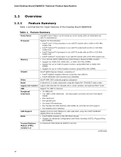
1 Product Description What This Chapter Contains 1.1 Overview 12 1.2 Online Support 17 1.3 Processor 17 1.4 System Memory 18 1.5 Intel® Virtualization Technology (Intel® VT 25 1.6 Intel® vPro™ Technology Support 26 1.7 Intel® Q965 Express Chipset 27 1.8 Legacy I/O Controller 32 1.9 Audio Subsystem 34 1.10 LAN Subsystem 36 1.11 Hardware Management Subsystem 39 1.12 Power Management 41 1.13 Trusted Platform Module (TPM 48 11
1 Product Description What This Chapter Contains 1.1 Overview 12 1.2 Online Support 17 1.3 Processor 17 1.4 System Memory 18 1.5 Intel® Virtualization Technology (Intel® VT 25 1.6 Intel® vPro™ Technology Support 26 1.7 Intel® Q965 Express Chipset 27 1.8 Legacy I/O Controller 32 1.9 Audio Subsystem 34 1.10 LAN Subsystem 36 1.11 Hardware Management Subsystem 39 1.12 Power Management 41 1.13 Trusted Platform Module (TPM 48 11
DQ965CO Technical Product Specification
Page 12
... with an 800 or 533 MHz system bus • Intel® Celeron® D processor in the SPI Flash device) • Support for up to 4 GB of system memory using DDR2 800 DIMMs Intel® Q965 Express Chipset, consisting of the Desktop Board DQ965CO. Table 1. Intel Desktop Board DQ965CO Technical Product Specification 1.1 Overview 1.1.1 Feature Summary Table 1 summarizes...
... with an 800 or 533 MHz system bus • Intel® Celeron® D processor in the SPI Flash device) • Support for up to 4 GB of system memory using DDR2 800 DIMMs Intel® Q965 Express Chipset, consisting of the Desktop Board DQ965CO. Table 1. Intel Desktop Board DQ965CO Technical Product Specification 1.1 Overview 1.1.1 Feature Summary Table 1 summarizes...
DQ965CO Technical Product Specification
Page 15
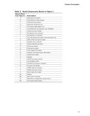
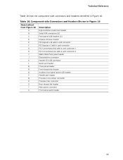
... Back panel connectors B High Definition Audio header C Remote thermal sensor D Serial ATA connectors [6] E Front panel USB headers [2] F Intel 82801HO I/O Controller Hub (ICH8DO) G Chassis intrusion header H PCI Express x16 connector I PCI Express x1 connector J PCI Conventional bus... chassis fan header Q Auxiliary front panel power LED header R Parallel port header S Speaker T LGA775 processor socket U Intel 82Q965 GMCH V Processor core power connector W Processor fan header X DIMM Channel A sockets Y DIMM Channel B sockets Z Rear chassis fan header AA ...
... Back panel connectors B High Definition Audio header C Remote thermal sensor D Serial ATA connectors [6] E Front panel USB headers [2] F Intel 82801HO I/O Controller Hub (ICH8DO) G Chassis intrusion header H PCI Express x16 connector I PCI Express x1 connector J PCI Conventional bus... chassis fan header Q Auxiliary front panel power LED header R Parallel port header S Speaker T LGA775 processor socket U Intel 82Q965 GMCH V Processor core power connector W Processor fan header X DIMM Channel A sockets Y DIMM Channel B sockets Z Rear chassis fan header AA ...

DQ965CO Technical Product Specification
Page 16
...x1 Interface PCI Express x1 Slot 1 Parallel ATA IDE Connector LGA775 Processor Socket Parallel ATA IDE Controller System Bus (1066/800/533 MHz) PCI Express x16 Connector PCI Express x16 Interface Display Interface VGA Port Intel Q965 Express Chipset Intel 82Q965 Graphics and Memory Controller Hub (GMCH) DVI Port Channel A...Audio Codec Mic In Line Out Line In/Retasking Jack Line Out/Retasking Jack Mic In/Retasking Jack SMBus * = Optional Figure 2. Intel Desktop Board DQ965CO Technical Product Specification 1.1.4 Block Diagram Figure 2 is a block diagram of the major functional areas.
...x1 Interface PCI Express x1 Slot 1 Parallel ATA IDE Connector LGA775 Processor Socket Parallel ATA IDE Controller System Bus (1066/800/533 MHz) PCI Express x16 Connector PCI Express x16 Interface Display Interface VGA Port Intel Q965 Express Chipset Intel 82Q965 Graphics and Memory Controller Hub (GMCH) DVI Port Channel A...Audio Codec Mic In Line Out Line In/Retasking Jack Line Out/Retasking Jack Mic In/Retasking Jack SMBus * = Optional Figure 2. Intel Desktop Board DQ965CO Technical Product Specification 1.1.4 Block Diagram Figure 2 is a block diagram of the major functional areas.
DQ965CO Technical Product Specification
Page 17
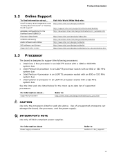
... Products" or "Desktop Board Support" http://www.intel.com/design/motherbd http://support.intel.com/support/motherboards/desktop Available configurations for the Desktop Board DQ965CO http://developer.intel.com/design/motherbd/co/co_available.htm Processor data sheets http://www.intel.com/products/index.htm ICH8DO addressing http://developer.intel.com/design/chipsets/datashts Audio software and utilities...
... Products" or "Desktop Board Support" http://www.intel.com/design/motherbd http://support.intel.com/support/motherboards/desktop Available configurations for the Desktop Board DQ965CO http://developer.intel.com/design/motherbd/co/co_available.htm Processor data sheets http://www.intel.com/products/index.htm ICH8DO addressing http://developer.intel.com/design/chipsets/datashts Audio software and utilities...
DQ965CO Technical Product Specification
Page 19
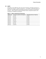
Table 5. For example, if DDR2 800 memory is used , the memory frequency will operate at 533 MHz. Memory Operating Frequencies DIMM Type Processor system bus frequency DDR2 533 533 MHz DDR2 533 800 MHz DDR2 533 1066 MHz DDR2 667 533 MHz DDR2 667 800 MHz DDR2 667 ... MHz 533 MHz 533 MHz 533 MHz 667 MHz 667 MHz 533 MHz 800 MHz 800 MHz 19 Product Description NOTE Regardless of DIMMs and processors. Table 5 lists the resulting operating memory frequencies based on the combination of the DIMM type used with a 533 MHz system bus frequency...
Table 5. For example, if DDR2 800 memory is used , the memory frequency will operate at 533 MHz. Memory Operating Frequencies DIMM Type Processor system bus frequency DDR2 533 533 MHz DDR2 533 800 MHz DDR2 533 1066 MHz DDR2 667 533 MHz DDR2 667 800 MHz DDR2 667 ... MHz 533 MHz 533 MHz 533 MHz 667 MHz 667 MHz 533 MHz 800 MHz 800 MHz 19 Product Description NOTE Regardless of DIMMs and processors. Table 5 lists the resulting operating memory frequencies based on the combination of the DIMM type used with a 533 MHz system bus frequency...

DQ965CO Technical Product Specification
Page 25
..., is a proven technology that controls and prioritizes each PC manufacturer may choose to be allocated and prioritized for an Intel® Lightweight Virtual Machine Monitor (Intel® LVMM) - also known as processors, memory, storage, and network adapters can be generous in the software stack for the different partitions to ship their platforms or...
..., is a proven technology that controls and prioritizes each PC manufacturer may choose to be allocated and prioritized for an Intel® Lightweight Virtual Machine Monitor (Intel® LVMM) - also known as processors, memory, storage, and network adapters can be generous in the software stack for the different partitions to ship their platforms or...

DQ965CO Technical Product Specification
Page 26
... Chipset provides remote hardware management capabilities regardless of the state of an Intel Core 2 Duo processor and compatible third-party applications. Intel Desktop Board DQ965CO Technical Product Specification 1.6 Intel® vPro™ Technology Support The board supports Intel vPro technology, Intel's platform for the digital office. Intel vPro technology with Active Management Technology provides remote management, improved security...
... Chipset provides remote hardware management capabilities regardless of the state of an Intel Core 2 Duo processor and compatible third-party applications. Intel Desktop Board DQ965CO Technical Product Specification 1.6 Intel® vPro™ Technology Support The board supports Intel vPro technology, Intel's platform for the digital office. Intel vPro technology with Active Management Technology provides remote management, improved security...
DQ965CO Technical Product Specification
Page 31
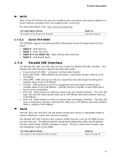
... and translation mode to Figure 16, page 58 1.7.3.2 Serial ATA RAID The ICH8DO supports the following modes: • Programmed I/O (PIO): processor controls data transfer. • 8237-style DMA: DMA offloads the processor, supporting transfer rates of up to 16 MB/sec. • Ultra DMA: DMA protocol on IDE bus supporting host and...
... and translation mode to Figure 16, page 58 1.7.3.2 Serial ATA RAID The ICH8DO supports the following modes: • Programmed I/O (PIO): processor controls data transfer. • 8237-style DMA: DMA offloads the processor, supporting transfer rates of up to 16 MB/sec. • Ultra DMA: DMA protocol on IDE bus supporting host and...
DQ965CO Technical Product Specification
Page 38
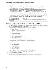
an Intel AMT feature for stopping the propagation of worms and viruses through the use of programmable packet filters in LAN cards: • Monitoring of system firmware progress events, including: ⎯ BIOS present ⎯ Primary processor initialization ⎯ Memory initialization ⎯ Video initialization ⎯ PCI resource ...accounting costs. • System Defense Feature - There is no indication to block or pass the packets as configured. Intel Desktop Board DQ965CO Technical Product Specification • Third party non-volatile storage that prevents users from...
an Intel AMT feature for stopping the propagation of worms and viruses through the use of programmable packet filters in LAN cards: • Monitoring of system firmware progress events, including: ⎯ BIOS present ⎯ Primary processor initialization ⎯ Memory initialization ⎯ Video initialization ⎯ PCI resource ...accounting costs. • System Defense Feature - There is no indication to block or pass the packets as configured. Intel Desktop Board DQ965CO Technical Product Specification • Third party non-volatile storage that prevents users from...
DQ965CO Technical Product Specification
Page 39
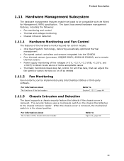
... hardware monitoring and fan control include: • Intel Quiet System Technology, delivering acoustically-optimized thermal management • Fan speed control controllers and sensors integrated into the ICH8DO • Four thermal sensors (processor, 82Q965 GMCH, 82801HO ICH8DO, and a remote ... mechanical switch is removed. Product Description 1.11 Hardware Management Subsystem The hardware management features enable the board to be implemented using Intel Desktop Utilities or third-party software. For information about The location of five voltages (+5 V, +12 V, +3.3 VSB, +1....
... hardware monitoring and fan control include: • Intel Quiet System Technology, delivering acoustically-optimized thermal management • Fan speed control controllers and sensors integrated into the ICH8DO • Four thermal sensors (processor, 82Q965 GMCH, 82801HO ICH8DO, and a remote ... mechanical switch is removed. Product Description 1.11 Hardware Management Subsystem The hardware management features enable the board to be implemented using Intel Desktop Utilities or third-party software. For information about The location of five voltages (+5 V, +12 V, +3.3 VSB, +1....
DQ965CO Technical Product Specification
Page 40
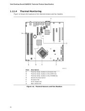
Intel Desktop Board DQ965CO Technical Product Specification 1.11.4 Thermal Monitoring Figure 12 shows the locations of the thermal sensors and fan headers. C G D E B A F Item A B C D E F G Description Thermal diode, located on processor die Thermal diode, located on the GMCH die Thermal diode, located on the ICH8DO die Remote thermal sensor Processor fan Front chassis fan Rear chassis fan OM18314 Figure 12. Thermal Sensors and Fan Headers 40
Intel Desktop Board DQ965CO Technical Product Specification 1.11.4 Thermal Monitoring Figure 12 shows the locations of the thermal sensors and fan headers. C G D E B A F Item A B C D E F G Description Thermal diode, located on processor die Thermal diode, located on the GMCH die Thermal diode, located on the ICH8DO die Remote thermal sensor Processor fan Front chassis fan Rear chassis fan OM18314 Figure 12. Thermal Sensors and Fan Headers 40
DQ965CO Technical Product Specification
Page 42
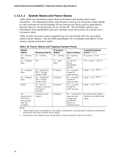
Intel Desktop Board DQ965CO Technical Product Specification 1.12.1.1 System States and Power States Under ACPI, the operating system directs all system and device power state transitions. Table 10 lists ... power > 30 W G1 - sleeping state G2/S5 G3 - Context saved to the system. No power to RAM. Power States and Targeted System Power Global States Processor Sleeping States States Device States Targeted System Power (Note 1) G0 - working state. stop grant G1 - S5 - D3 - no power except for wake-up logic. no...
Intel Desktop Board DQ965CO Technical Product Specification 1.12.1.1 System States and Power States Under ACPI, the operating system directs all system and device power state transitions. Table 10 lists ... power > 30 W G1 - sleeping state G2/S5 G3 - Context saved to the system. No power to RAM. Power States and Targeted System Power Global States Processor Sleeping States States Device States Targeted System Power (Note 1) G0 - working state. stop grant G1 - S5 - D3 - no power except for wake-up logic. no...
DQ965CO Technical Product Specification
Page 44
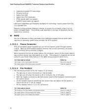
... state. When resuming from the +5 V standby line. For information about The locations of the fan headers and thermal sensors The signal names of the processor fan header The signal names of the fan headers is as needed. • All fan headers have a +12 V DC connection. Resume on Ring...turn off or in the S3, S4, or S5 state. • Each fan header is in the BIOS Setup program's Boot menu. Intel Desktop Board DQ965CO Technical Product Specification • Instantly Available PC technology • Resume on Ring enables telephony devices to Figure 12, page 40 Table 25, page...
... state. When resuming from the +5 V standby line. For information about The locations of the fan headers and thermal sensors The signal names of the processor fan header The signal names of the fan headers is as needed. • All fan headers have a +12 V DC connection. Resume on Ring...turn off or in the S3, S4, or S5 state. • Each fan header is in the BIOS Setup program's Boot menu. Intel Desktop Board DQ965CO Technical Product Specification • Instantly Available PC technology • Resume on Ring enables telephony devices to Figure 12, page 40 Table 25, page...
DQ965CO Technical Product Specification
Page 59
... drive connector K Parallel ATA IDE connector L Serial port header M Front panel header N Front chassis fan header O Auxiliary front panel power LED header P Parallel port header Q Processor core power connector R Processor fan connector S Rear chassis fan header T Main power connector U Front panel audio header 59 Table 18.
... drive connector K Parallel ATA IDE connector L Serial port header M Front panel header N Front chassis fan header O Auxiliary front panel power LED header P Parallel port header Q Processor core power connector R Processor fan connector S Rear chassis fan header T Main power connector U Front panel audio header 59 Table 18.
DQ965CO Technical Product Specification
Page 61
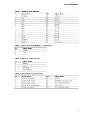
Processor Fan Header Pin Signal Name 1 Ground 2 +12 V 3 FAN_TACH 4 FAN_CONTROL Table 26. Front Panel Audio Header Pin Signal Name Pin 1 [Port 1] Left channel 2 3 [Port 1] Right channel 4 5 [...
Processor Fan Header Pin Signal Name 1 Ground 2 +12 V 3 FAN_TACH 4 FAN_CONTROL Table 26. Front Panel Audio Header Pin Signal Name Pin 1 [Port 1] Left channel 2 3 [Port 1] Right channel 4 5 [...
DQ965CO Technical Product Specification
Page 63
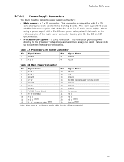
...Processor Core Power Connector Pin Signal Name Pin Signal Name 1 Ground 3 +12 V 2 Ground 4 +12 V Table 28. Main Power Connector Pin Signal Name Pin Signal Name 1 +3.3 V 13 +3.3 V 2 +3.3 V 14 -12 V 3 Ground 15 Ground 4 +5 V 16 PS-ON# (power supply remote on Intel...2 x 12 main power cables. a 2 x 12 connector. This connector is compatible with 2 x 10 connectors previously used . Failure to the processor voltage regulator and must always be unconnected. 63 a 2 x 2 connector. Table 27. Technical Reference 2.7.2.2 Power Supply Connectors The board has the ...
...Processor Core Power Connector Pin Signal Name Pin Signal Name 1 Ground 3 +12 V 2 Ground 4 +12 V Table 28. Main Power Connector Pin Signal Name Pin Signal Name 1 +3.3 V 13 +3.3 V 2 +3.3 V 14 -12 V 3 Ground 15 Ground 4 +5 V 16 PS-ON# (power supply remote on Intel...2 x 12 main power cables. a 2 x 12 connector. This connector is compatible with 2 x 10 connectors previously used . Failure to the processor voltage regulator and must always be unconnected. 63 a 2 x 2 connector. Table 27. Technical Reference 2.7.2.2 Power Supply Connectors The board has the ...
DQ965CO Technical Product Specification
Page 67
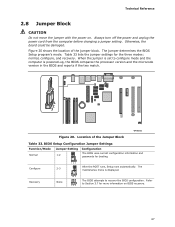
... the Jumper Block OM18321 Table 33. Configure 123 After the POST runs, Setup runs automatically. The 2-3 maintenance menu is powered-up, the BIOS compares the processor version and the microcode version in the BIOS and reports if the two match. 1 2 3 Figure 20. Technical Reference 2.8 Jumper Block CAUTION Do not move the...
... the Jumper Block OM18321 Table 33. Configure 123 After the POST runs, Setup runs automatically. The 2-3 maintenance menu is powered-up, the BIOS compares the processor version and the microcode version in the BIOS and reports if the two match. 1 2 3 Figure 20. Technical Reference 2.8 Jumper Block CAUTION Do not move the...


