
Product Specification
Page 5
... 21 1.11.2 Audio Headers and Connectors 22 1.12 LAN Subsystem 23 1.12.1 Intel® 82578DM Gigabit Ethernet Controller 23 1.12.2 LAN Subsystem Software 23 1.12.3 RJ-45 LAN Connector with Integrated LEDs 24 1.13 Real-Time Clock Subsystem 25 1.14 Thermal Monitoring 26 1.15 Platform ...Management and Security 27 1.15.1 Hardware Management Subsystem 27 1.15.2 Intel® vPro™ Technology 28 1.16 Power Management 33 1.16.1...
... 21 1.11.2 Audio Headers and Connectors 22 1.12 LAN Subsystem 23 1.12.1 Intel® 82578DM Gigabit Ethernet Controller 23 1.12.2 LAN Subsystem Software 23 1.12.3 RJ-45 LAN Connector with Integrated LEDs 24 1.13 Real-Time Clock Subsystem 25 1.14 Thermal Monitoring 26 1.15 Platform ...Management and Security 27 1.15.1 Hardware Management Subsystem 27 1.15.2 Intel® vPro™ Technology 28 1.16 Power Management 33 1.16.1...
Product Specification
Page 6
Intel Desktop Board DQ57TM Technical Product Specification 2.4 Clear CMOS Header 58 2.5 Mechanical Considerations 59 2.5.1 Form Factor 59 2.6 Electrical Considerations 60 2.6.1 Power Supply Considerations 60 2.6.2 Fan Header Current ...Hard Disk Drive Password Security Feature 71 3.8 BIOS Security Features 72 4 Error Messages and Beep Codes 4.1 Speaker 75 4.2 BIOS Beep Codes 75 4.3 Front-panel Power LED Blink Codes 76 4.4 BIOS Error Messages 76 4.5 Port 80h POST Codes 77 5 Regulatory Compliance and Battery Disposal Information 5.1 Regulatory Compliance 83 5.1.1 Safety Standards 83 ...
Intel Desktop Board DQ57TM Technical Product Specification 2.4 Clear CMOS Header 58 2.5 Mechanical Considerations 59 2.5.1 Form Factor 59 2.6 Electrical Considerations 60 2.6.1 Power Supply Considerations 60 2.6.2 Fan Header Current ...Hard Disk Drive Password Security Feature 71 3.8 BIOS Security Features 72 4 Error Messages and Beep Codes 4.1 Speaker 75 4.2 BIOS Beep Codes 75 4.3 Front-panel Power LED Blink Codes 76 4.4 BIOS Error Messages 76 4.5 Port 80h POST Codes 77 5 Regulatory Compliance and Battery Disposal Information 5.1 Regulatory Compliance 83 5.1.1 Safety Standards 83 ...

Product Specification
Page 7
...35 8. S/PDIF Header 49 13. Front Panel Audio Header for a One-Color Power LED 54 26. Front Panel USB Header 50 17. SATA Connectors 50 18. Processor (4-Pin) Fan Header 51 20. Intel Remote PC Assist Technology Header 51 22. Block Diagram 13 3. Thermal Sensors and Fan ... and Rear Chassis Fan Headers 51 21. Connection Diagram for Front Panel USB Headers 55 14. Location of Pressing the Power Switch 34 7. Intel ME "M" State LED Behavior 30 6. Component-side Connectors and Headers Shown in Figure 1 12 3. Main Power Connector 52 24. Front Panel Header 53 25. ...
...35 8. S/PDIF Header 49 13. Front Panel Audio Header for a One-Color Power LED 54 26. Front Panel USB Header 50 17. SATA Connectors 50 18. Processor (4-Pin) Fan Header 51 20. Intel Remote PC Assist Technology Header 51 22. Block Diagram 13 3. Thermal Sensors and Fan ... and Rear Chassis Fan Headers 51 21. Connection Diagram for Front Panel USB Headers 55 14. Location of Pressing the Power Switch 34 7. Intel ME "M" State LED Behavior 30 6. Component-side Connectors and Headers Shown in Figure 1 12 3. Main Power Connector 52 24. Front Panel Header 53 25. ...
Product Specification
Page 8
... 61 31. BIOS Beep Codes 75 40. Thermal Considerations for BIOS Recovery 69 36. Typical Port 80h POST Sequence 81 45. Intel Desktop Board DQ57TM Technical Product Specification 27. Recommended Power Supply Current Values 60 30. BIOS Setup Program Menu Bar 66 34. BIOS Error Messages 76... Supervisor and User Password Functions 73 39. Port 80h POST Codes 78 44. Boot Device Menu Options 70 37. Front-panel Power LED Blink Codes 76 41. Acceptable Drives/Media Types for Components 63 32. Lead-Free Board Markings 88 47. BIOS Setup Configuration Jumper ...
... 61 31. BIOS Beep Codes 75 40. Thermal Considerations for BIOS Recovery 69 36. Typical Port 80h POST Sequence 81 45. Intel Desktop Board DQ57TM Technical Product Specification 27. Recommended Power Supply Current Values 60 30. BIOS Setup Program Menu Bar 66 34. BIOS Error Messages 76... Supervisor and User Password Functions 73 39. Port 80h POST Codes 78 44. Boot Device Menu Options 70 37. Front-panel Power LED Blink Codes 76 41. Acceptable Drives/Media Types for Components 63 32. Lead-Free Board Markings 88 47. BIOS Setup Configuration Jumper ...

Product Specification
Page 12
... S Front panel header T Standby power LED U Intel ME "M" state LED V Front panel USB headers (4) W Intel Q57 Express Chipset X BIOS setup configuration jumper block Y Clear CMOS header Z Intel Remote PC Assist header AA Serial port header BB S/PDIF header CC Front panel audio header DD Internal mono speaker header 12 Intel Desktop Board DQ57TM Technical Product Specification Table 2.
... S Front panel header T Standby power LED U Intel ME "M" state LED V Front panel USB headers (4) W Intel Q57 Express Chipset X BIOS setup configuration jumper block Y Clear CMOS header Z Intel Remote PC Assist header AA Serial port header BB S/PDIF header CC Front panel audio header DD Internal mono speaker header 12 Intel Desktop Board DQ57TM Technical Product Specification Table 2.
Product Specification
Page 23
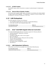
...segmentation • Full device driver compatibility • PCI Express power management support • Intel AMT 6.0 1.12.2 LAN Subsystem Software LAN software and drivers are available from Intel's World Wide Web site. Product Description 1.11.2.2 S/PDIF Header The S/PDIF header allows .... For information about LAN software and drivers Refer to http://downloadcenter.intel.com 1.12.1 Intel® 82578DM Gigabit Ethernet Controller The Intel 82578DM Gigabit Ethernet Controller supports the following : • Intel 82578DM Gigabit Ethernet Controller (10/100/1000 Mbits/s) • RJ...
...segmentation • Full device driver compatibility • PCI Express power management support • Intel AMT 6.0 1.12.2 LAN Subsystem Software LAN software and drivers are available from Intel's World Wide Web site. Product Description 1.11.2.2 S/PDIF Header The S/PDIF header allows .... For information about LAN software and drivers Refer to http://downloadcenter.intel.com 1.12.1 Intel® 82578DM Gigabit Ethernet Controller The Intel 82578DM Gigabit Ethernet Controller supports the following : • Intel 82578DM Gigabit Ethernet Controller (10/100/1000 Mbits/s) • RJ...
Product Specification
Page 24
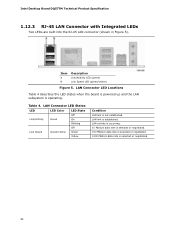
... when the board is powered up and the LAN subsystem is not established. LAN Connector LED States LED LED Color LED State Off Link/Activity Green On Blinking Link Speed Green/Yellow Off Green Yellow Condition LAN link is operating. Table 4.... data rate is selected or negotiated. 1000 Mbits/s data rate is established. Item A B Description Link/Activity LED (green) Link Speed LED (green/yellow) Figure 5. Intel Desktop Board DQ57TM Technical Product Specification 1.12.3 RJ-45 LAN Connector with Integrated LEDs Two LEDs are built into the RJ-45 LAN connector (shown in Figure 5).
... when the board is powered up and the LAN subsystem is not established. LAN Connector LED States LED LED Color LED State Off Link/Activity Green On Blinking Link Speed Green/Yellow Off Green Yellow Condition LAN link is operating. Table 4.... data rate is selected or negotiated. 1000 Mbits/s data rate is established. Item A B Description Link/Activity LED (green) Link Speed LED (green/yellow) Figure 5. Intel Desktop Board DQ57TM Technical Product Specification 1.12.3 RJ-45 LAN Connector with Integrated LEDs Two LEDs are built into the RJ-45 LAN connector (shown in Figure 5).
Product Specification
Page 28
...GUI ⎯ XML/SOAP API ⎯ Web Services for Management (WS-MAN) protocol support 28 Intel Desktop Board DQ57TM Technical Product Specification 1.15.2 Intel® vPro™ Technology Intel® vPro™ Technology is a set of processor and platform capabilities designed to offering encrypted and... BIOS/SPI Flash (64 Mbits) • On-board Intel ME "M" state status LED NOTE Software with AMT capability is required to take advantage of Intel AMT platform management capabilities. 1.15.2.1.1 Intel AMT Features The key features of Intel AMT include: • Secure Out of Band (OOB...
...GUI ⎯ XML/SOAP API ⎯ Web Services for Management (WS-MAN) protocol support 28 Intel Desktop Board DQ57TM Technical Product Specification 1.15.2 Intel® vPro™ Technology Intel® vPro™ Technology is a set of processor and platform capabilities designed to offering encrypted and... BIOS/SPI Flash (64 Mbits) • On-board Intel ME "M" state status LED NOTE Software with AMT capability is required to take advantage of Intel AMT platform management capabilities. 1.15.2.1.1 Intel AMT Features The key features of Intel AMT include: • Secure Out of Band (OOB...
Product Specification
Page 30
... Intel® ME WMI provider • Intel® Active Management Technology NAC Posture Plug-in sleep state after Intel ME timeout has occurred Table 5 shows expected behavior of the platform. Table 5. Intel ME "M" State LED Behavior Sx/M3 Sx/Moff S0/M0 LED ... information about Intel Active Management Technology (Intel AMT) Refer to http://www.intel.com/technology/platformtechnology/intel-amt/index.htm 1.15.2.1.2 Intel AMT Software and Drivers Intel AMT software and drivers are available from Intel's World Wide Web site. Intel Desktop Board DQ57TM Technical Product ...
... Intel® ME WMI provider • Intel® Active Management Technology NAC Posture Plug-in sleep state after Intel ME timeout has occurred Table 5 shows expected behavior of the platform. Table 5. Intel ME "M" State LED Behavior Sx/M3 Sx/Moff S0/M0 LED ... information about Intel Active Management Technology (Intel AMT) Refer to http://www.intel.com/technology/platformtechnology/intel-amt/index.htm 1.15.2.1.2 Intel AMT Software and Drivers Intel AMT software and drivers are available from Intel's World Wide Web site. Intel Desktop Board DQ57TM Technical Product ...

Product Specification
Page 31
It accomplishes this by using a measured launch and leveraging Intel VT to produce a protected environment for the execution of the Intel ME "M" State LED 1.15.2.2 Intel® Virtualization Technology (Intel® VT) Intel Virtualization Technology (Intel VT) is a processor technology that enables a platform to run multiple operating systems and applications as independent machines, allowing one computer system to...
It accomplishes this by using a measured launch and leveraging Intel VT to produce a protected environment for the execution of the Intel ME "M" State LED 1.15.2.2 Intel® Virtualization Technology (Intel® VT) Intel Virtualization Technology (Intel VT) is a processor technology that enables a platform to run multiple operating systems and applications as independent machines, allowing one computer system to...

Product Specification
Page 37
... • Wake from USB • PME# signal wake-up support • WAKE# signal wake-up support • Wake from serial port • +5 V Standby Power Indicator LED LAN wake capabilities and Instantly Available PC technology require power from an AC power failure, the computer returns to the power state it was interrupted...
... • Wake from USB • PME# signal wake-up support • WAKE# signal wake-up support • Wake from serial port • +5 V Standby Power Indicator LED LAN wake capabilities and Instantly Available PC technology require power from an AC power failure, the computer returns to the power state it was interrupted...
Product Specification
Page 39
... technology enables the board to enter the ACPI S3 (Suspend-toRAM) sleep-state. NOTE Wake from USB requires the use of the Standby Power indicator LED on a PCI Express add-in cards, and drivers. 1.16.2.5 Wake from USB USB bus activity wakes the computer from the S3 state. Add-in boards... that can participate in the S3 sleep-state, the computer will appear to be off and the front panel power LED will behave as configured by a wake-up Support When the WAKE# signal on the board. 39 The board supports the PCI Bus Power Management Interface...
... technology enables the board to enter the ACPI S3 (Suspend-toRAM) sleep-state. NOTE Wake from USB requires the use of the Standby Power indicator LED on a PCI Express add-in cards, and drivers. 1.16.2.5 Wake from USB USB bus activity wakes the computer from the S3 state. Add-in boards... that can participate in the S3 sleep-state, the computer will appear to be off and the front panel power LED will behave as configured by a wake-up Support When the WAKE# signal on the board. 39 The board supports the PCI Bus Power Management Interface...

Product Specification
Page 40
Location of the Standby Power LED (Green) 40 Intel Desktop Board DQ57TM Technical Product Specification CAUTION If AC power has been switched off and the standby power indicators are still lit, disconnect the power cord before installing or removing any attached devices. Failure to do so could damage the board and any devices connected to the board. Figure 8.
Location of the Standby Power LED (Green) 40 Intel Desktop Board DQ57TM Technical Product Specification CAUTION If AC power has been switched off and the standby power indicators are still lit, disconnect the power cord before installing or removing any attached devices. Failure to do so could damage the board and any devices connected to the board. Figure 8.
Product Specification
Page 53
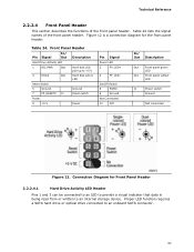
...4 FP_LED− On/Off Switch 6 PWR# 8 Ground Not Connected 10 N/C In/ Out Description Out Front panel green LED Out Front panel yellow LED In Power switch Ground Not connected Figure 12. Technical Reference 2.2.2.4 Front Panel Header This section describes the functions of the front ...panel header. Front Panel Header Pin Signal In/ Out Description Hard Drive Activity LED 1 HD_PWR Out Hard disk LED pull-up to an onboard SATA connector. 53 Figure 12 is being read from or written to provide a visual indicator...
...4 FP_LED− On/Off Switch 6 PWR# 8 Ground Not Connected 10 N/C In/ Out Description Out Front panel green LED Out Front panel yellow LED In Power switch Ground Not connected Figure 12. Technical Reference 2.2.2.4 Front Panel Header This section describes the functions of the front ...panel header. Front Panel Header Pin Signal In/ Out Description Hard Drive Activity LED 1 HD_PWR Out Hard disk LED pull-up to an onboard SATA connector. 53 Figure 12 is being read from or written to provide a visual indicator...
Product Specification
Page 54
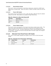
... power supply will recognize another on pins 2 and 4 of this LED. Table 25 shows the default states for a One-Color Power LED LED State Description Off Power off signal. 2.2.2.5 Alternate Front Panel Power LED Header Pins 1 and 3 of the front panel header. Intel Desktop Board DQ57TM Technical Product Specification 2.2.2.4.2 Reset Switch Header Pins 5 and 7 can be...
... power supply will recognize another on pins 2 and 4 of this LED. Table 25 shows the default states for a One-Color Power LED LED State Description Off Power off signal. 2.2.2.5 Alternate Front Panel Power LED Header Pins 1 and 3 of the front panel header. Intel Desktop Board DQ57TM Technical Product Specification 2.2.2.4.2 Reset Switch Header Pins 5 and 7 can be...
Product Specification
Page 76
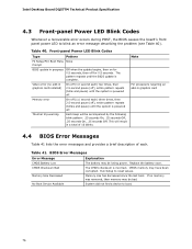
... times, then 2.5-second pause (off), entire pattern repeats (blink and pause) until the system is powered off for 0.5 seconds, then off . Replace the battery soon. Intel Desktop Board DQ57TM Technical Product Specification 4.3 Front-panel Power LED Blink Codes Whenever a recoverable error occurs during POST, the BIOS causes the board's front panel power...
... times, then 2.5-second pause (off), entire pattern repeats (blink and pause) until the system is powered off for 0.5 seconds, then off . Replace the battery soon. Intel Desktop Board DQ57TM Technical Product Specification 4.3 Front-panel Power LED Blink Codes Whenever a recoverable error occurs during POST, the BIOS causes the board's front panel power...
Intel Desktop Board DQ57TML Technical Product Specification
Page 5
... 21 1.11.2 Audio Headers and Connectors 22 1.12 LAN Subsystem 23 1.12.1 Intel® 82578DM Gigabit Ethernet Controller 23 1.12.2 LAN Subsystem Software 23 1.12.3 RJ-45 LAN Connector with Integrated LEDs 24 1.13 Real-Time Clock Subsystem 25 1.14 Thermal Monitoring 26 1.15 Platform ...Management and Security 27 1.15.1 Hardware Management Subsystem 27 1.15.2 Intel® vPro™ Technology 28 1.16 Power Management 34 1.16.1...
... 21 1.11.2 Audio Headers and Connectors 22 1.12 LAN Subsystem 23 1.12.1 Intel® 82578DM Gigabit Ethernet Controller 23 1.12.2 LAN Subsystem Software 23 1.12.3 RJ-45 LAN Connector with Integrated LEDs 24 1.13 Real-Time Clock Subsystem 25 1.14 Thermal Monitoring 26 1.15 Platform ...Management and Security 27 1.15.1 Hardware Management Subsystem 27 1.15.2 Intel® vPro™ Technology 28 1.16 Power Management 34 1.16.1...
Intel Desktop Board DQ57TML Technical Product Specification
Page 6
... DQ57TML Technical Product Specification 2.4 Intel® Management Engine BIOS Extension (Intel® MEBx) Reset Header 59 2.5 Mechanical Considerations 60 2.5.1 Form Factor 60 2.6 Electrical Considerations 61 2.6.1 Power Supply Considerations 61 2.6.2 Fan...Drive Password Security Feature 73 3.8 BIOS Security Features 74 4 Error Messages and Beep Codes 4.1 Speaker 77 4.2 BIOS Beep Codes 77 4.3 Front-panel Power LED Blink Codes 78 4.4 BIOS Error Messages 78 4.5 Port 80h POST Codes 79 5 Regulatory Compliance and Battery Disposal Information 5.1 Regulatory Compliance 85 5.1.1 Safety ...
... DQ57TML Technical Product Specification 2.4 Intel® Management Engine BIOS Extension (Intel® MEBx) Reset Header 59 2.5 Mechanical Considerations 60 2.5.1 Form Factor 60 2.6 Electrical Considerations 61 2.6.1 Power Supply Considerations 61 2.6.2 Fan...Drive Password Security Feature 73 3.8 BIOS Security Features 74 4 Error Messages and Beep Codes 4.1 Speaker 77 4.2 BIOS Beep Codes 77 4.3 Front-panel Power LED Blink Codes 78 4.4 BIOS Error Messages 78 4.5 Port 80h POST Codes 79 5 Regulatory Compliance and Battery Disposal Information 5.1 Regulatory Compliance 85 5.1.1 Safety ...

Intel Desktop Board DQ57TML Technical Product Specification
Page 7
...26 7. Location of Pressing the Power Switch 34 8. Connection Diagram for AC '97 Audio 49 19. Supported Memory Configurations 15 4. Intel ME "M" State LED Behavior 31 7. Power States and Targeted System Power 35 9. System Memory Map 43 11. Parallel Port Header 47 14. Chassis ... Localized High Temperature Zones 64 Tables 1. Components Shown in Figure 11 46 12. Audio Jack Retasking Support 21 5. Effects of the Intel ME "M" State LED 31 8. Wake-up Devices and Events 36 10. Component-side Connectors and Headers Shown in Figure 1 12 3. S/PDIF Header 48 ...
...26 7. Location of Pressing the Power Switch 34 8. Connection Diagram for AC '97 Audio 49 19. Supported Memory Configurations 15 4. Intel ME "M" State LED Behavior 31 7. Power States and Targeted System Power 35 9. System Memory Map 43 11. Parallel Port Header 47 14. Chassis ... Localized High Temperature Zones 64 Tables 1. Components Shown in Figure 11 46 12. Audio Jack Retasking Support 21 5. Effects of the Intel ME "M" State LED 31 8. Wake-up Devices and Events 36 10. Component-side Connectors and Headers Shown in Figure 1 12 3. S/PDIF Header 48 ...
Intel Desktop Board DQ57TML Technical Product Specification
Page 8
... Current Values 61 34. Acceptable Drives/Media Types for a One-Color Power LED 55 30. Typical Port 80h POST Sequence 83 49. EMC Regulations 89 51. Intel Desktop Board DQ57TML Technical Product Specification 27. Intel MEBx Reset Header Signals 59 33. Environmental Specifications 65 37. Master Key and...Fan Header Current Capability 62 35. BIOS Setup Program Menu Bar 68 38. Port 80h POST Codes 80 48. Alternate Front Panel Power LED Header 55 31. Supervisor and User Password Functions 75 43. Main Power Connector 53 28. BIOS Setup Configuration Jumper Settings 58 32....
... Current Values 61 34. Acceptable Drives/Media Types for a One-Color Power LED 55 30. Typical Port 80h POST Sequence 83 49. EMC Regulations 89 51. Intel Desktop Board DQ57TML Technical Product Specification 27. Intel MEBx Reset Header Signals 59 33. Environmental Specifications 65 37. Master Key and...Fan Header Current Capability 62 35. BIOS Setup Program Menu Bar 68 38. Port 80h POST Codes 80 48. Alternate Front Panel Power LED Header 55 31. Supervisor and User Password Functions 75 43. Main Power Connector 53 28. BIOS Setup Configuration Jumper Settings 58 32....


