
Product Specification
Page 5
... Controller 21 1.10.1 Serial Port 21 1.11 Audio Subsystem 21 1.11.1 Audio Subsystem Software 21 1.11.2 Audio Headers and Connectors 22 1.12 LAN Subsystem 23 1.12.1 Intel® 82578DM Gigabit Ethernet Controller 23 1.12.2 LAN Subsystem Software 23 1.12.3 RJ-45 LAN Connector with Integrated LEDs... STAR* 5.0, e-Standby, and ErP Compliance 41 2 Technical Reference 2.1 Memory Resources 43 2.1.1 Addressable Memory 43 2.1.2 Memory Map 45 2.2 Connectors and Headers 45 2.2.1 Back Panel Connectors 46 2.2.2 Component-side Connectors and Headers 47 2.3 BIOS Configuration Jumper Block 56 v
... Controller 21 1.10.1 Serial Port 21 1.11 Audio Subsystem 21 1.11.1 Audio Subsystem Software 21 1.11.2 Audio Headers and Connectors 22 1.12 LAN Subsystem 23 1.12.1 Intel® 82578DM Gigabit Ethernet Controller 23 1.12.2 LAN Subsystem Software 23 1.12.3 RJ-45 LAN Connector with Integrated LEDs... STAR* 5.0, e-Standby, and ErP Compliance 41 2 Technical Reference 2.1 Memory Resources 43 2.1.1 Addressable Memory 43 2.1.2 Memory Map 45 2.2 Connectors and Headers 45 2.2.1 Back Panel Connectors 46 2.2.2 Component-side Connectors and Headers 47 2.3 BIOS Configuration Jumper Block 56 v

Product Specification
Page 7
... Fan Headers 26 7. CMOS Clear Header 58 16. Intel ME "M" State LED Behavior 30 6. Internal Mono Speaker Header 49 14. Main Power Connector 52 24. Alternate Front Panel Power LED Header 54 vii Location of the Intel ME "M" State LED 31 8. Connection Diagram for Intel HD Audio 49 15. Serial Port Header 49 12. Front Panel Audio Header for Front Panel Header 53...
... Fan Headers 26 7. CMOS Clear Header 58 16. Intel ME "M" State LED Behavior 30 6. Internal Mono Speaker Header 49 14. Main Power Connector 52 24. Alternate Front Panel Power LED Header 54 vii Location of the Intel ME "M" State LED 31 8. Connection Diagram for Intel HD Audio 49 15. Serial Port Header 49 12. Front Panel Audio Header for Front Panel Header 53...

Product Specification
Page 12
... power connector (2 x 12) Q SATA connectors R Alternate front panel power LED header S Front panel header T Standby power LED U Intel ME "M" state LED V Front panel USB headers (4) W Intel Q57 Express Chipset X BIOS setup configuration jumper block Y Clear CMOS header Z Intel Remote PC Assist header AA Serial port header BB S/PDIF header CC Front panel audio header DD Internal mono speaker header 12 Intel Desktop Board DQ57TM Technical Product Specification Table 2.
... power connector (2 x 12) Q SATA connectors R Alternate front panel power LED header S Front panel header T Standby power LED U Intel ME "M" state LED V Front panel USB headers (4) W Intel Q57 Express Chipset X BIOS setup configuration jumper block Y Clear CMOS header Z Intel Remote PC Assist header AA Serial port header BB S/PDIF header CC Front panel audio header DD Internal mono speaker header 12 Intel Desktop Board DQ57TM Technical Product Specification Table 2.
Product Specification
Page 53
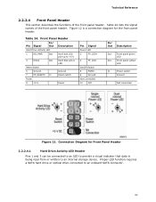
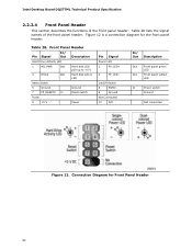
... section describes the functions of the front panel header. Connection Diagram for the front panel header. Front Panel Header Pin Signal In/ Out Description Hard Drive Activity LED 1 HD_PWR Out Hard disk LED pull-up to an onboard SATA connector....6 PWR# 8 Ground Not Connected 10 N/C In/ Out Description Out Front panel green LED Out Front panel yellow LED In Power switch Ground Not connected Figure 12. Figure 12 is a connection diagram for Front Panel Header 2.2.2.4.1 Hard Drive Activity LED Header Pins 1 and 3 can be connected to an LED to provide a visual...
... section describes the functions of the front panel header. Connection Diagram for the front panel header. Front Panel Header Pin Signal In/ Out Description Hard Drive Activity LED 1 HD_PWR Out Hard disk LED pull-up to an onboard SATA connector....6 PWR# 8 Ground Not Connected 10 N/C In/ Out Description Out Front panel green LED Out Front panel yellow LED In Power switch Ground Not connected Figure 12. Figure 12 is a connection diagram for Front Panel Header 2.2.2.4.1 Hard Drive Activity LED Header Pins 1 and 3 can be connected to an LED to provide a visual...
Product Specification
Page 54
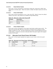
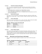
..., the board resets and runs the POST. 2.2.2.4.3 Power LED Header Pins 2 and 4 can be connected to a one- Table 25. Intel Desktop Board DQ57TM Technical Product Specification 2.2.2.4.2 Reset Switch Header Pins 5 and 7 can be connected to internal debounce circuitry ...on the board.) At least two seconds must pull the SW_ON# pin to ground for at least 50 ms to signal the power supply to switch on pins 2 and 4 of the front panel header...
..., the board resets and runs the POST. 2.2.2.4.3 Power LED Header Pins 2 and 4 can be connected to a one- Table 25. Intel Desktop Board DQ57TM Technical Product Specification 2.2.2.4.2 Reset Switch Header Pins 5 and 7 can be connected to internal debounce circuitry ...on the board.) At least two seconds must pull the SW_ON# pin to ground for at least 50 ms to signal the power supply to switch on pins 2 and 4 of the front panel header...

Intel Desktop Board DQ57TML Technical Product Specification
Page 7
... Port Header 47 14. Front Panel USB Header 49 20. LAN Connector LED Locations 24 6. Intel ME "M" State LED Behavior 31 7. Component-side Connectors and Headers Shown in Figure 1 12 3. Internal Mono Speaker Header 48 16. Intel Remote PC Assist Technology Header 50 25. Back Panel Audio Connectors 22 5. Connection Diagram for Front Panel Header 54 13. Intel MEBx Reset Header 59 16...
... Port Header 47 14. Front Panel USB Header 49 20. LAN Connector LED Locations 24 6. Intel ME "M" State LED Behavior 31 7. Component-side Connectors and Headers Shown in Figure 1 12 3. Internal Mono Speaker Header 48 16. Intel Remote PC Assist Technology Header 50 25. Back Panel Audio Connectors 22 5. Connection Diagram for Front Panel Header 54 13. Intel MEBx Reset Header 59 16...
Intel Desktop Board DQ57TML Technical Product Specification
Page 8
...68 38. Port 80h POST Code Ranges 79 47. Port 80h POST Codes 80 48. Alternate Front Panel Power LED Header 55 31. BIOS Setup Program Function Keys 68 39. Typical Port 80h POST Sequence 83 49. ...78 46. Safety Standards 85 50. Intel Desktop Board DQ57TML Technical Product Specification 27. Fan Header Current Capability 62 35. Master Key and User Hard Drive Password Functions 73 42. Front-panel Power LED Blink Codes 78 45. BIOS... One-Color Power LED 55 30. EMC Regulations 89 51. Front Panel Header 54 29. Intel MEBx Reset Header Signals 59 33.
...68 38. Port 80h POST Code Ranges 79 47. Port 80h POST Codes 80 48. Alternate Front Panel Power LED Header 55 31. BIOS Setup Program Function Keys 68 39. Typical Port 80h POST Sequence 83 49. ...78 46. Safety Standards 85 50. Intel Desktop Board DQ57TML Technical Product Specification 27. Fan Header Current Capability 62 35. Master Key and User Hard Drive Password Functions 73 42. Front-panel Power LED Blink Codes 78 45. BIOS... One-Color Power LED 55 30. EMC Regulations 89 51. Front Panel Header 54 29. Intel MEBx Reset Header Signals 59 33.

Intel Desktop Board DQ57TML Technical Product Specification
Page 12
... header T Front panel header U Standby power LED V Front panel USB header (with Intel Z-U130 USB Solid-State Drive, or compatible device, support) W Intel ME "M" state LED X Intel Q57 Express Chipset Y Front panel USB headers (3) Z BIOS setup configuration jumper block AA Intel® Management Engine BIOS Extension (Intel® MEBx) Reset header BB Intel Remote PC Assist header CC Serial port header DD S/PDIF header EE Front panel audio header...
... header T Front panel header U Standby power LED V Front panel USB header (with Intel Z-U130 USB Solid-State Drive, or compatible device, support) W Intel ME "M" state LED X Intel Q57 Express Chipset Y Front panel USB headers (3) Z BIOS setup configuration jumper block AA Intel® Management Engine BIOS Extension (Intel® MEBx) Reset header BB Intel Remote PC Assist header CC Serial port header DD S/PDIF header EE Front panel audio header...

Intel Desktop Board DQ57TML Technical Product Specification
Page 46
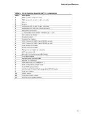
Component-side Connectors and Headers Shown in Figure 11 Item/callout from Figure 11 A B C D E F G H I J K ...header Processor fan header Front chassis fan header Chassis intrusion header Diskette drive connector Main power connector (2 x 12) SATA connectors Alternate front panel power LED header N Front panel header O Front panel USB header (with Intel Z-U130 USB Solid-State Drive, or compatible device, support) P Front panel USB headers (3) Q Intel Remote PC Assist header R Serial port header S S/PDIF header T Front panel audio header U Internal mono speaker header 46 Intel...
Component-side Connectors and Headers Shown in Figure 11 Item/callout from Figure 11 A B C D E F G H I J K ...header Processor fan header Front chassis fan header Chassis intrusion header Diskette drive connector Main power connector (2 x 12) SATA connectors Alternate front panel power LED header N Front panel header O Front panel USB header (with Intel Z-U130 USB Solid-State Drive, or compatible device, support) P Front panel USB headers (3) Q Intel Remote PC Assist header R Serial port header S S/PDIF header T Front panel audio header U Internal mono speaker header 46 Intel...
Intel Desktop Board DQ57TML Technical Product Specification
Page 54
Intel Desktop Board DQ57TML Technical Product Specification 2.2.2.4 Front Panel Header This section describes the functions of the front panel header. Table 28 lists the signal names of the front panel header. Table 28. Front Panel Header Pin Signal In/ Out Description Hard Drive Activity LED 1 ... Switch 6 PWR# 8 Ground Not Connected 10 N/C In/ Out Description Out Front panel green LED Out Front panel yellow LED In Power switch Ground Not connected Figure 12. Figure 12 is a connection diagram for Front Panel Header 54 Connection Diagram for the front...
Intel Desktop Board DQ57TML Technical Product Specification 2.2.2.4 Front Panel Header This section describes the functions of the front panel header. Table 28 lists the signal names of the front panel header. Table 28. Front Panel Header Pin Signal In/ Out Description Hard Drive Activity LED 1 ... Switch 6 PWR# 8 Ground Not Connected 10 N/C In/ Out Description Out Front panel green LED Out Front panel yellow LED In Power switch Ground Not connected Figure 12. Figure 12 is a connection diagram for Front Panel Header 54 Connection Diagram for the front...
Intel Desktop Board DQ57TML Technical Product Specification
Page 55
... the SW_ON# pin to ground for this header duplicate the signals on /off /sleeping Steady Lit Running Blink Standby 2.2.2.4.4 Power Switch Header Pins 6 and 8 can be connected to a one of the front panel header. Alternate Front Panel Power LED Header Pin Signal Name 1 FP_LED+ 2 Not ...onboard PATA connector • Intel Z-U130 USB Solid State Drive (or compatible device) connected to one - Table 30. The switch must pass before the power supply will recognize another on pins 2 and 4 of the front panel USB headers 2.2.2.4.2 Reset Switch Header Pins 5 and 7 can...
... the SW_ON# pin to ground for this header duplicate the signals on /off /sleeping Steady Lit Running Blink Standby 2.2.2.4.4 Power Switch Header Pins 6 and 8 can be connected to a one of the front panel header. Alternate Front Panel Power LED Header Pin Signal Name 1 FP_LED+ 2 Not ...onboard PATA connector • Intel Z-U130 USB Solid State Drive (or compatible device) connected to one - Table 30. The switch must pass before the power supply will recognize another on pins 2 and 4 of the front panel USB headers 2.2.2.4.2 Reset Switch Header Pins 5 and 7 can...

Intel Desktop Board DQ57TM Product Guide English
Page 6
Intel Desktop Board DQ57TM Product Guide Installing and Removing a Processor 37 Installing a Processor 37 Installing a Processor Fan Heat Sink 42 Connecting the Processor Fan Heat Sink Cable 42 ...Card 49 Connecting Serial ATA (SATA) Cables 50 Connecting to the Internal Headers 51 Front Panel Audio Header 52 Internal Mono Speaker Header 52 S/PDIF Header 53 Chassis Intrusion Header 53 Alternate Front Panel Power LED Header 53 Front Panel Header 54 Front Panel USB 2.0 Headers 54 Intel RPAT Header 55 Serial Header 55 Connecting to the Audio System 56 Connecting Chassis Fan and Power...
Intel Desktop Board DQ57TM Product Guide Installing and Removing a Processor 37 Installing a Processor 37 Installing a Processor Fan Heat Sink 42 Connecting the Processor Fan Heat Sink Cable 42 ...Card 49 Connecting Serial ATA (SATA) Cables 50 Connecting to the Internal Headers 51 Front Panel Audio Header 52 Internal Mono Speaker Header 52 S/PDIF Header 53 Chassis Intrusion Header 53 Alternate Front Panel Power LED Header 53 Front Panel Header 54 Front Panel USB 2.0 Headers 54 Intel RPAT Header 55 Serial Header 55 Connecting to the Audio System 56 Connecting Chassis Fan and Power...
Intel Desktop Board DQ57TM Product Guide English
Page 8
... Regulations 84 25. Chassis Intrusion Header Signal Names 53 11. Jumper Settings for Intel HD Audio 52 7. BIOS Error Messages 74 21. Intel Desktop Board DQ57TM Product Guide Tables 1. Master Key and User Hard Disk Drive Password Functions 21 5. Alternate Front Panel Power LED Header Signal Names 53 12. Front Panel Audio Header Signal Names for AC '97...
... Regulations 84 25. Chassis Intrusion Header Signal Names 53 11. Jumper Settings for Intel HD Audio 52 7. BIOS Error Messages 74 21. Intel Desktop Board DQ57TM Product Guide Tables 1. Master Key and User Hard Disk Drive Password Functions 21 5. Alternate Front Panel Power LED Header Signal Names 53 12. Front Panel Audio Header Signal Names for AC '97...
Intel Desktop Board DQ57TM Product Guide English
Page 13
... Table 2. Intel Desktop Board DQ57TM Components Label A B C D E F G H I J K L M N O P Q R S T U V W X Y Z AA BB CC Description PCI bus add-in card connector PCI Express 2.0 x1 add-in card connector Battery Speaker PCI Express 2.0 x1 add-in card connector PCI Express 2.0 x16 add-in card connector Back panel connectors 12 V processor core voltage connector (2 x 2 pin) Rear chassis fan header Processor...
... Table 2. Intel Desktop Board DQ57TM Components Label A B C D E F G H I J K L M N O P Q R S T U V W X Y Z AA BB CC Description PCI bus add-in card connector PCI Express 2.0 x1 add-in card connector Battery Speaker PCI Express 2.0 x1 add-in card connector PCI Express 2.0 x16 add-in card connector Back panel connectors 12 V processor core voltage connector (2 x 2 pin) Rear chassis fan header Processor...

Intel Desktop Board DQ57TM Product Guide English
Page 53
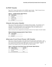
... Names Pin Description 1 Intruder# 2 Ground Alternate Front Panel Power LED Header Figure 23, E shows the location of the chassis intrusion header. This switch should be connected to detect if the chassis cover is removed. Table 11. Table 11 shows the pin assignments for the alternate front panel header. Installing and Replacing Desktop Board Components S/PDIF...
... Names Pin Description 1 Intruder# 2 Ground Alternate Front Panel Power LED Header Figure 23, E shows the location of the chassis intrusion header. This switch should be connected to detect if the chassis cover is removed. Table 11. Table 11 shows the pin assignments for the alternate front panel header. Installing and Replacing Desktop Board Components S/PDIF...
Intel Desktop Board DQ57TM Product Guide English
Page 54
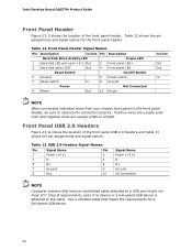
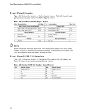
.... Table 12 shows the pin assignments and signal names for a full-speed USB device. 54 Table 12. Front Panel USB 2.0 Headers Figure 23, G shows the location of the front panel header. USB 2.0 Headers Signal Names Pin Signal Name Pin 1 Power (+5 V) 2 3 D- 4 5 D+ 6 7 Ground 8 9...Panel Header Signal Names Pin Description In/Out Pin Description Hard Disk Drive Activity LED Power LED 1 Hard disk LED pull-up to observe the connection polarity. Intel Desktop Board DQ57TM Product Guide Front Panel Header Figure 23, F shows the location of the front panel USB 2.0 headers...
.... Table 12 shows the pin assignments and signal names for a full-speed USB device. 54 Table 12. Front Panel USB 2.0 Headers Figure 23, G shows the location of the front panel header. USB 2.0 Headers Signal Names Pin Signal Name Pin 1 Power (+5 V) 2 3 D- 4 5 D+ 6 7 Ground 8 9...Panel Header Signal Names Pin Description In/Out Pin Description Hard Disk Drive Activity LED Power LED 1 Hard disk LED pull-up to observe the connection polarity. Intel Desktop Board DQ57TM Product Guide Front Panel Header Figure 23, F shows the location of the front panel USB 2.0 headers...

Intel Desktop Board DQ57TM Product Guide English
Page 6
...or Compatible Device 54 Connecting to the Internal Headers 55 Front Panel Audio Header 56 Internal Mono Speaker Header 56 S/PDIF Header 57 Chassis Intrusion Header 57 Alternate Front Panel Power LED Header 57 Front Panel Header 58 Front Panel USB 2.0 Headers 58 Intel RPAT Header 59 Serial Header 59 Connecting to the Audio System 60 ... Clearing Passwords in the BIOS Setup Program 64 Replacing the Battery 65 3 Updating the BIOS Updating the BIOS with the Intel® Express BIOS Update Utility 71 Updating the BIOS with the ISO Image BIOS Update File or the Iflash Memory Update...
...or Compatible Device 54 Connecting to the Internal Headers 55 Front Panel Audio Header 56 Internal Mono Speaker Header 56 S/PDIF Header 57 Chassis Intrusion Header 57 Alternate Front Panel Power LED Header 57 Front Panel Header 58 Front Panel USB 2.0 Headers 58 Intel RPAT Header 59 Serial Header 59 Connecting to the Audio System 60 ... Clearing Passwords in the BIOS Setup Program 64 Replacing the Battery 65 3 Updating the BIOS Updating the BIOS with the Intel® Express BIOS Update Utility 71 Updating the BIOS with the ISO Image BIOS Update File or the Iflash Memory Update...

Intel Desktop Board DQ57TM Product Guide English
Page 8
...Signal Names 59 15. Serial Port Header 59 17. Jumper Settings for the BIOS Setup Program Modes 64 18. Location of the BIOS Configuration Jumper Block 63 31. Intel Desktop Board DQ57TML Components 13 3. BIOS Beep Codes 77 19. Front Panel Header Signal Names 58 13. Regulatory ...Compliance Marks 88 viii Intel ME "M" State LED Behavior 25 6. Master Key and User Hard Disk ...
...Signal Names 59 15. Serial Port Header 59 17. Jumper Settings for the BIOS Setup Program Modes 64 18. Location of the BIOS Configuration Jumper Block 63 31. Intel Desktop Board DQ57TML Components 13 3. BIOS Beep Codes 77 19. Front Panel Header Signal Names 58 13. Regulatory ...Compliance Marks 88 viii Intel ME "M" State LED Behavior 25 6. Master Key and User Hard Disk ...
Intel Desktop Board DQ57TM Product Guide English
Page 57
... be in the open position when the chassis cover is installed and closed when the cover is removed. Chassis Intrusion Header Signal Names Pin Description 1 Intruder# 2 Ground Alternate Front Panel Power LED Header Figure 26, F shows the location of the front panel header. Table 9 shows the pin assignments and signal names for the S/PDIF output...
... be in the open position when the chassis cover is installed and closed when the cover is removed. Chassis Intrusion Header Signal Names Pin Description 1 Intruder# 2 Ground Alternate Front Panel Power LED Header Figure 26, F shows the location of the front panel header. Table 9 shows the pin assignments and signal names for the S/PDIF output...
Intel Desktop Board DQ57TM Product Guide English
Page 58
Intel Desktop Board DQ57TM Product Guide Front Panel Header Figure 26, G shows the location of the standard front panel USB 2.0 headers and Table 13 shows the pin assignments and signal names. Standard USB 2.0 Headers Signal Names Pin Signal Name 1 Power (+5 V) 3 D- 5 D+ 7 Ground 9 Key Pin Signal Name 2 Power (+5 V) 4 D- 6 D+ 8 Ground 10 No Connection 58 Front Panel USB 2.0 Headers Figure 26, H shows the location...
Intel Desktop Board DQ57TM Product Guide Front Panel Header Figure 26, G shows the location of the standard front panel USB 2.0 headers and Table 13 shows the pin assignments and signal names. Standard USB 2.0 Headers Signal Names Pin Signal Name 1 Power (+5 V) 3 D- 5 D+ 7 Ground 9 Key Pin Signal Name 2 Power (+5 V) 4 D- 6 D+ 8 Ground 10 No Connection 58 Front Panel USB 2.0 Headers Figure 26, H shows the location...


