
Product Specification
Page 5
... Controller 21 1.10.1 Serial Port 21 1.11 Audio Subsystem 21 1.11.1 Audio Subsystem Software 21 1.11.2 Audio Headers and Connectors 22 1.12 LAN Subsystem 23 1.12.1 Intel® 82578DM Gigabit Ethernet Controller 23 1.12.2 LAN Subsystem Software 23 1.12.3 RJ-45 LAN Connector with Integrated LEDs... STAR* 5.0, e-Standby, and ErP Compliance 41 2 Technical Reference 2.1 Memory Resources 43 2.1.1 Addressable Memory 43 2.1.2 Memory Map 45 2.2 Connectors and Headers 45 2.2.1 Back Panel Connectors 46 2.2.2 Component-side Connectors and Headers 47 2.3 BIOS Configuration Jumper Block 56 v
... Controller 21 1.10.1 Serial Port 21 1.11 Audio Subsystem 21 1.11.1 Audio Subsystem Software 21 1.11.2 Audio Headers and Connectors 22 1.12 LAN Subsystem 23 1.12.1 Intel® 82578DM Gigabit Ethernet Controller 23 1.12.2 LAN Subsystem Software 23 1.12.3 RJ-45 LAN Connector with Integrated LEDs... STAR* 5.0, e-Standby, and ErP Compliance 41 2 Technical Reference 2.1 Memory Resources 43 2.1.1 Addressable Memory 43 2.1.2 Memory Map 45 2.2 Connectors and Headers 45 2.2.1 Back Panel Connectors 46 2.2.2 Component-side Connectors and Headers 47 2.3 BIOS Configuration Jumper Block 56 v

Product Specification
Page 7
... 24 6. Connection Diagram for a One-Color Power LED 54 26. Intel ME "M" State LED Behavior 30 6. Power States and Targeted System Power 35 8. Serial Port Header 49 12. Internal Mono Speaker Header 49 14. Intel Remote PC Assist Technology Header 51 22. States for Front Panel Header 53 13. Location of Pressing the Power Switch 34 7. Component...
... 24 6. Connection Diagram for a One-Color Power LED 54 26. Intel ME "M" State LED Behavior 30 6. Power States and Targeted System Power 35 8. Serial Port Header 49 12. Internal Mono Speaker Header 49 14. Intel Remote PC Assist Technology Header 51 22. States for Front Panel Header 53 13. Location of Pressing the Power Switch 34 7. Component...

Product Specification
Page 12
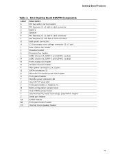
... power connector (2 x 12) Q SATA connectors R Alternate front panel power LED header S Front panel header T Standby power LED U Intel ME "M" state LED V Front panel USB headers (4) W Intel Q57 Express Chipset X BIOS setup configuration jumper block Y Clear CMOS header Z Intel Remote PC Assist header AA Serial port header BB S/PDIF header CC Front panel audio header DD Internal mono speaker header 12 Intel Desktop Board DQ57TM Technical Product Specification Table 2.
... power connector (2 x 12) Q SATA connectors R Alternate front panel power LED header S Front panel header T Standby power LED U Intel ME "M" state LED V Front panel USB headers (4) W Intel Q57 Express Chipset X BIOS setup configuration jumper block Y Clear CMOS header Z Intel Remote PC Assist header AA Serial port header BB S/PDIF header CC Front panel audio header DD Internal mono speaker header 12 Intel Desktop Board DQ57TM Technical Product Specification Table 2.
Product Specification
Page 53
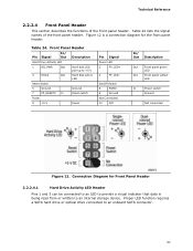
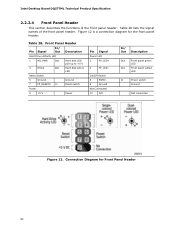
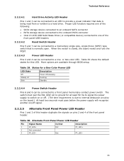
...requires a SATA hard drive or optical drive connected to an internal storage device. Figure 12 is a connection diagram for Front Panel Header 2.2.2.4.1 Hard Drive Activity LED Header Pins 1 and 3 can be connected to an LED to provide a visual indicator that data is being read from or written... to an onboard SATA connector. 53 Connection Diagram for the front panel header. Front Panel Header Pin Signal In/ Out Description Hard Drive Activity LED 1 HD_PWR Out Hard disk LED pull-up to +5 V 3 HDA# Out ...
...requires a SATA hard drive or optical drive connected to an internal storage device. Figure 12 is a connection diagram for Front Panel Header 2.2.2.4.1 Hard Drive Activity LED Header Pins 1 and 3 can be connected to an LED to provide a visual indicator that data is being read from or written... to an onboard SATA connector. 53 Connection Diagram for the front panel header. Front Panel Header Pin Signal In/ Out Description Hard Drive Activity LED 1 HD_PWR Out Hard disk LED pull-up to +5 V 3 HDA# Out ...
Product Specification
Page 54
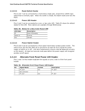
...on pins 2 and 4 of this LED. Table 26. Table 25. More options are available through BIOS setup. Intel Desktop Board DQ57TM Technical Product Specification 2.2.2.4.2 Reset Switch Header Pins 5 and 7 can be connected to a momentary single pole, single throw (SPST) type switch that is ...least 50 ms to signal the power supply to switch on or off signal. 2.2.2.5 Alternate Front Panel Power LED Header Pins 1 and 3 of the front panel header. Alternate Front Panel Power LED Header Pin Signal Name In/Out Description 1 FP_LED+ Out 2 Not connected 3 FP_LED− Out ...
...on pins 2 and 4 of this LED. Table 26. Table 25. More options are available through BIOS setup. Intel Desktop Board DQ57TM Technical Product Specification 2.2.2.4.2 Reset Switch Header Pins 5 and 7 can be connected to a momentary single pole, single throw (SPST) type switch that is ...least 50 ms to signal the power supply to switch on or off signal. 2.2.2.5 Alternate Front Panel Power LED Header Pins 1 and 3 of the front panel header. Alternate Front Panel Power LED Header Pin Signal Name In/Out Description 1 FP_LED+ Out 2 Not connected 3 FP_LED− Out ...

Intel Desktop Board DQ57TML Technical Product Specification
Page 7
... 15. Power States and Targeted System Power 35 9. S/PDIF Header 48 15. Front Panel Audio Header for Front Panel Header 54 13. SATA Connectors 49 21. Front and Rear Chassis Fan Headers 50 24. Back Panel Audio Connectors 22 5. Component-side Connectors and Headers 45 12. Connection Diagram for Intel HD Audio 48 17. Feature Summary 9 2. System Memory Map...
... 15. Power States and Targeted System Power 35 9. S/PDIF Header 48 15. Front Panel Audio Header for Front Panel Header 54 13. SATA Connectors 49 21. Front and Rear Chassis Fan Headers 50 24. Back Panel Audio Connectors 22 5. Component-side Connectors and Headers 45 12. Connection Diagram for Intel HD Audio 48 17. Feature Summary 9 2. System Memory Map...
Intel Desktop Board DQ57TML Technical Product Specification
Page 8
... Codes 77 44. BIOS Error Messages 78 46. Port 80h POST Codes 80 48. Regulatory Compliance Marks 93 viii Alternate Front Panel Power LED Header 55 31. Recommended Power Supply Current Values 61 34. BIOS Setup Program Function Keys 68 39. Master Key and User Hard Drive... Functions 75 43. Typical Port 80h POST Sequence 83 49. States for BIOS Recovery 71 40. Front-panel Power LED Blink Codes 78 45. Front Panel Header 54 29. Intel MEBx Reset Header Signals 59 33. Thermal Considerations for Components 64 36. Environmental Specifications 65 37. BIOS Setup Program Menu...
... Codes 77 44. BIOS Error Messages 78 46. Port 80h POST Codes 80 48. Regulatory Compliance Marks 93 viii Alternate Front Panel Power LED Header 55 31. Recommended Power Supply Current Values 61 34. BIOS Setup Program Function Keys 68 39. Master Key and User Hard Drive... Functions 75 43. Typical Port 80h POST Sequence 83 49. States for BIOS Recovery 71 40. Front-panel Power LED Blink Codes 78 45. Front Panel Header 54 29. Intel MEBx Reset Header Signals 59 33. Thermal Considerations for Components 64 36. Environmental Specifications 65 37. BIOS Setup Program Menu...

Intel Desktop Board DQ57TML Technical Product Specification
Page 12
... header T Front panel header U Standby power LED V Front panel USB header (with Intel Z-U130 USB Solid-State Drive, or compatible device, support) W Intel ME "M" state LED X Intel Q57 Express Chipset Y Front panel USB headers (3) Z BIOS setup configuration jumper block AA Intel® Management Engine BIOS Extension (Intel® MEBx) Reset header BB Intel Remote PC Assist header CC Serial port header DD S/PDIF header EE Front panel audio header...
... header T Front panel header U Standby power LED V Front panel USB header (with Intel Z-U130 USB Solid-State Drive, or compatible device, support) W Intel ME "M" state LED X Intel Q57 Express Chipset Y Front panel USB headers (3) Z BIOS setup configuration jumper block AA Intel® Management Engine BIOS Extension (Intel® MEBx) Reset header BB Intel Remote PC Assist header CC Serial port header DD S/PDIF header EE Front panel audio header...

Intel Desktop Board DQ57TML Technical Product Specification
Page 46
... (ATX12V) Rear chassis fan header Processor fan header Front chassis fan header Chassis intrusion header Diskette drive connector Main power connector (2 x 12) SATA connectors Alternate front panel power LED header N Front panel header O Front panel USB header (with Intel Z-U130 USB Solid-State Drive, or compatible device, support) P Front panel USB headers (3) Q Intel Remote PC Assist header R Serial port header S S/PDIF header T Front panel audio header U Internal mono speaker...
... (ATX12V) Rear chassis fan header Processor fan header Front chassis fan header Chassis intrusion header Diskette drive connector Main power connector (2 x 12) SATA connectors Alternate front panel power LED header N Front panel header O Front panel USB header (with Intel Z-U130 USB Solid-State Drive, or compatible device, support) P Front panel USB headers (3) Q Intel Remote PC Assist header R Serial port header S S/PDIF header T Front panel audio header U Internal mono speaker...
Intel Desktop Board DQ57TML Technical Product Specification
Page 54
Table 28 lists the signal names of the front panel header. Table 28. Connection Diagram for the front panel header. Figure 12 is a connection diagram for Front Panel Header 54 Front Panel Header Pin Signal In/ Out Description Hard Drive Activity LED 1 HD_PWR Out ... PWR# 8 Ground Not Connected 10 N/C In/ Out Description Out Front panel green LED Out Front panel yellow LED In Power switch Ground Not connected Figure 12. Intel Desktop Board DQ57TML Technical Product Specification 2.2.2.4 Front Panel Header This section describes the functions of the front...
Table 28 lists the signal names of the front panel header. Table 28. Connection Diagram for the front panel header. Figure 12 is a connection diagram for Front Panel Header 54 Front Panel Header Pin Signal In/ Out Description Hard Drive Activity LED 1 HD_PWR Out ... PWR# 8 Ground Not Connected 10 N/C In/ Out Description Out Front panel green LED Out Front panel yellow LED In Power switch Ground Not connected Figure 12. Intel Desktop Board DQ57TML Technical Product Specification 2.2.2.4 Front Panel Header This section describes the functions of the front...
Intel Desktop Board DQ57TML Technical Product Specification
Page 55
...the default states for at least 50 ms to signal the power supply to switch on or off signal. 2.2.2.5 Alternate Front Panel Power LED Header Pins 1 and 3 of this LED. Proper LED function requires one of the following: • SATA storage device connected...Intel Z-U130 USB Solid State Drive (or compatible device) connected to one - The switch must pass before the power supply will recognize another on pins 2 and 4 of the front panel USB headers 2.2.2.4.2 Reset Switch Header Pins 5 and 7 can be connected to a one of the front panel header. Alternate Front Panel Power LED Header...
...the default states for at least 50 ms to signal the power supply to switch on or off signal. 2.2.2.5 Alternate Front Panel Power LED Header Pins 1 and 3 of this LED. Proper LED function requires one of the following: • SATA storage device connected...Intel Z-U130 USB Solid State Drive (or compatible device) connected to one - The switch must pass before the power supply will recognize another on pins 2 and 4 of the front panel USB headers 2.2.2.4.2 Reset Switch Header Pins 5 and 7 can be connected to a one of the front panel header. Alternate Front Panel Power LED Header...

Intel Desktop Board DQ57TM Product Guide English
Page 6
Intel Desktop Board DQ57TM Product Guide Installing and Removing a Processor 37 Installing a Processor 37 Installing a Processor Fan Heat Sink 42 Connecting the Processor Fan Heat Sink Cable 42 ...Card 49 Connecting Serial ATA (SATA) Cables 50 Connecting to the Internal Headers 51 Front Panel Audio Header 52 Internal Mono Speaker Header 52 S/PDIF Header 53 Chassis Intrusion Header 53 Alternate Front Panel Power LED Header 53 Front Panel Header 54 Front Panel USB 2.0 Headers 54 Intel RPAT Header 55 Serial Header 55 Connecting to the Audio System 56 Connecting Chassis Fan and Power...
Intel Desktop Board DQ57TM Product Guide Installing and Removing a Processor 37 Installing a Processor 37 Installing a Processor Fan Heat Sink 42 Connecting the Processor Fan Heat Sink Cable 42 ...Card 49 Connecting Serial ATA (SATA) Cables 50 Connecting to the Internal Headers 51 Front Panel Audio Header 52 Internal Mono Speaker Header 52 S/PDIF Header 53 Chassis Intrusion Header 53 Alternate Front Panel Power LED Header 53 Front Panel Header 54 Front Panel USB 2.0 Headers 54 Intel RPAT Header 55 Serial Header 55 Connecting to the Audio System 56 Connecting Chassis Fan and Power...
Intel Desktop Board DQ57TM Product Guide English
Page 8
... 21. Product Certification Markings 86 viii LAN Status LEDs States 18 4. Front Panel Audio Header Signal Names for AC '97 Audio 52 8. Chassis Intrusion Header Signal Names 53 11. Front Panel Header Signal Names 54 13. Lead-Free Second Level Interconnect Marks 81 23. Intel Desktop Board DQ57TM Components 13 3. Intel ME "M" State LED Behavior 25 6. Feature Summary 9 2.
... 21. Product Certification Markings 86 viii LAN Status LEDs States 18 4. Front Panel Audio Header Signal Names for AC '97 Audio 52 8. Chassis Intrusion Header Signal Names 53 11. Front Panel Header Signal Names 54 13. Lead-Free Second Level Interconnect Marks 81 23. Intel Desktop Board DQ57TM Components 13 3. Intel ME "M" State LED Behavior 25 6. Feature Summary 9 2.
Intel Desktop Board DQ57TM Product Guide English
Page 13
... Table 2. Intel Desktop Board DQ57TM Components Label A B C D E F G H I J K L M N O P Q R S T U V W X Y Z AA BB CC Description PCI bus add-in card connector PCI Express 2.0 x1 add-in card connector Battery Speaker PCI Express 2.0 x1 add-in card connector PCI Express 2.0 x16 add-in card connector Back panel connectors 12 V processor core voltage connector (2 x 2 pin) Rear chassis fan header Processor...
... Table 2. Intel Desktop Board DQ57TM Components Label A B C D E F G H I J K L M N O P Q R S T U V W X Y Z AA BB CC Description PCI bus add-in card connector PCI Express 2.0 x1 add-in card connector Battery Speaker PCI Express 2.0 x1 add-in card connector PCI Express 2.0 x16 add-in card connector Back panel connectors 12 V processor core voltage connector (2 x 2 pin) Rear chassis fan header Processor...

Intel Desktop Board DQ57TM Product Guide English
Page 53
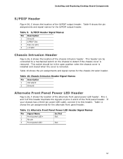
... shows the pin assignments for the chassis intrusion header. S/PDIF Header Signal Names Pin Description 1 Ground 2 S/PDIF Out 3 Key (no pin) 4 +5 VDC Chassis Intrusion Header Figure 23, D shows the location of the front panel header. Table 10 shows the pin assignments and signal names for the alternate front panel header. Table 9 shows the pin assignments and signal...
... shows the pin assignments for the chassis intrusion header. S/PDIF Header Signal Names Pin Description 1 Ground 2 S/PDIF Out 3 Key (no pin) 4 +5 VDC Chassis Intrusion Header Figure 23, D shows the location of the front panel header. Table 10 shows the pin assignments and signal names for the alternate front panel header. Table 9 shows the pin assignments and signal...
Intel Desktop Board DQ57TM Product Guide English
Page 54
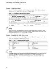
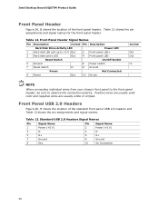
...NOTE When connecting individual wires from your chassis front panel to the front panel header, be sure to +5 V Out 2 Front panel LED+ 3 Hard disk active LED Out 4 Front panel LED- Front Panel USB 2.0 Headers Figure 23, G shows the location of the front panel header. Table 13. USB 2.0 Headers Signal Names Pin Signal Name Pin 1 Power ... Hard disk LED pull-up to observe the connection polarity. Intel Desktop Board DQ57TM Product Guide Front Panel Header Figure 23, F shows the location of the front panel USB 2.0 headers and Table 13 shows the pin assignments and signal names....
...NOTE When connecting individual wires from your chassis front panel to the front panel header, be sure to +5 V Out 2 Front panel LED+ 3 Hard disk active LED Out 4 Front panel LED- Front Panel USB 2.0 Headers Figure 23, G shows the location of the front panel header. Table 13. USB 2.0 Headers Signal Names Pin Signal Name Pin 1 Power ... Hard disk LED pull-up to observe the connection polarity. Intel Desktop Board DQ57TM Product Guide Front Panel Header Figure 23, F shows the location of the front panel USB 2.0 headers and Table 13 shows the pin assignments and signal names....

Intel Desktop Board DQ57TM Product Guide English
Page 6
...or Compatible Device 54 Connecting to the Internal Headers 55 Front Panel Audio Header 56 Internal Mono Speaker Header 56 S/PDIF Header 57 Chassis Intrusion Header 57 Alternate Front Panel Power LED Header 57 Front Panel Header 58 Front Panel USB 2.0 Headers 58 Intel RPAT Header 59 Serial Header 59 Connecting to the Audio System 60 ... Clearing Passwords in the BIOS Setup Program 64 Replacing the Battery 65 3 Updating the BIOS Updating the BIOS with the Intel® Express BIOS Update Utility 71 Updating the BIOS with the ISO Image BIOS Update File or the Iflash Memory Update...
...or Compatible Device 54 Connecting to the Internal Headers 55 Front Panel Audio Header 56 Internal Mono Speaker Header 56 S/PDIF Header 57 Chassis Intrusion Header 57 Alternate Front Panel Power LED Header 57 Front Panel Header 58 Front Panel USB 2.0 Headers 58 Intel RPAT Header 59 Serial Header 59 Connecting to the Audio System 60 ... Clearing Passwords in the BIOS Setup Program 64 Replacing the Battery 65 3 Updating the BIOS Updating the BIOS with the Intel® Express BIOS Update Utility 71 Updating the BIOS with the ISO Image BIOS Update File or the Iflash Memory Update...

Intel Desktop Board DQ57TM Product Guide English
Page 8
... 1. Internal Mono Speaker Header 56 9. Chassis Intrusion Header Signal Names 57 11. Front Panel USB Header with Intel Z-U130 USB Solid-State Drive or Compatible Device Support Signal Names 59 15. BIOS Error Messages 78 21. Front Panel Audio Signal Names for AC '97 Audio 56 8. S/PDIF Header Signal Names 57 10. Front Panel Header Signal Names 58 13...
... 1. Internal Mono Speaker Header 56 9. Chassis Intrusion Header Signal Names 57 11. Front Panel USB Header with Intel Z-U130 USB Solid-State Drive or Compatible Device Support Signal Names 59 15. BIOS Error Messages 78 21. Front Panel Audio Signal Names for AC '97 Audio 56 8. S/PDIF Header Signal Names 57 10. Front Panel Header Signal Names 58 13...
Intel Desktop Board DQ57TM Product Guide English
Page 57
... chassis cover is removed. In/Out Out Out 57 S/PDIF Header Signal Names Pin Description 1 Ground 2 S/PDIF Out 3 Key (no pin) 4 +5 VDC Chassis Intrusion Header Figure 26, E shows the location of the front panel header. This header can be in the open position when the chassis cover is... installed and closed when the cover is removed. Pins 1 and 3 of this header duplicate the signals on the chassis to this...
... chassis cover is removed. In/Out Out Out 57 S/PDIF Header Signal Names Pin Description 1 Ground 2 S/PDIF Out 3 Key (no pin) 4 +5 VDC Chassis Intrusion Header Figure 26, E shows the location of the front panel header. This header can be in the open position when the chassis cover is... installed and closed when the cover is removed. Pins 1 and 3 of this header duplicate the signals on the chassis to this...
Intel Desktop Board DQ57TM Product Guide English
Page 58
... Hard Disk Drive Activity LED Power LED 1 Hard disk LED pull-up to observe the connection polarity. Intel Desktop Board DQ57TM Product Guide Front Panel Header Figure 26, G shows the location of the standard front panel USB 2.0 headers and Table 13 shows the pin assignments and signal names. Table 12 shows the pin assignments and signal...
... Hard Disk Drive Activity LED Power LED 1 Hard disk LED pull-up to observe the connection polarity. Intel Desktop Board DQ57TM Product Guide Front Panel Header Figure 26, G shows the location of the standard front panel USB 2.0 headers and Table 13 shows the pin assignments and signal names. Table 12 shows the pin assignments and signal...


