
Product Specification
Page 5
... LEDs 24 1.13 Real-Time Clock Subsystem 25 1.14 Thermal Monitoring 26 1.15 Platform Management and Security 27 1.15.1 Hardware Management Subsystem 27 1.15.2 Intel® vPro™ Technology 28 1.16 Power Management 33 1.16.1 ACPI 34 1.16.2 Hardware Support 37 1.16.3 ENERGY STAR* 5.0, e-Standby, and... ErP Compliance 41 2 Technical Reference 2.1 Memory Resources 43 2.1.1 Addressable Memory 43 2.1.2 Memory Map 45 2.2 Connectors and Headers 45 2.2.1 Back Panel Connectors 46 2.2.2 Component-side Connectors and Headers 47 2.3 BIOS Configuration Jumper Block 56 v
... LEDs 24 1.13 Real-Time Clock Subsystem 25 1.14 Thermal Monitoring 26 1.15 Platform Management and Security 27 1.15.1 Hardware Management Subsystem 27 1.15.2 Intel® vPro™ Technology 28 1.16 Power Management 33 1.16.1 ACPI 34 1.16.2 Hardware Support 37 1.16.3 ENERGY STAR* 5.0, e-Standby, and... ErP Compliance 41 2 Technical Reference 2.1 Memory Resources 43 2.1.1 Addressable Memory 43 2.1.2 Memory Map 45 2.2 Connectors and Headers 45 2.2.1 Back Panel Connectors 46 2.2.2 Component-side Connectors and Headers 47 2.3 BIOS Configuration Jumper Block 56 v
Product Specification
Page 6
Intel Desktop Board DQ57TM Technical Product Specification 2.4 Clear CMOS Header 58 2.5 Mechanical Considerations 59 2.5.1 Form Factor 59 2.6 Electrical Considerations 60 2.6.1 Power Supply Considerations 60 2.6.2 Fan Header Current Capability... 3.7 Hard Disk Drive Password Security Feature 71 3.8 BIOS Security Features 72 4 Error Messages and Beep Codes 4.1 Speaker 75 4.2 BIOS Beep Codes 75 4.3 Front-panel Power LED Blink Codes 76 4.4 BIOS Error Messages 76 4.5 Port 80h POST Codes 77 5 Regulatory Compliance and Battery Disposal Information 5.1 Regulatory Compliance 83 5.1.1 Safety ...
Intel Desktop Board DQ57TM Technical Product Specification 2.4 Clear CMOS Header 58 2.5 Mechanical Considerations 59 2.5.1 Form Factor 59 2.6 Electrical Considerations 60 2.6.1 Power Supply Considerations 60 2.6.2 Fan Header Current Capability... 3.7 Hard Disk Drive Password Security Feature 71 3.8 BIOS Security Features 72 4 Error Messages and Beep Codes 4.1 Speaker 75 4.2 BIOS Beep Codes 75 4.3 Front-panel Power LED Blink Codes 76 4.4 BIOS Error Messages 76 4.5 Port 80h POST Codes 77 5 Regulatory Compliance and Battery Disposal Information 5.1 Regulatory Compliance 83 5.1.1 Safety ...

Product Specification
Page 7
... System Memory Map 45 10. Internal Mono Speaker Header 49 14. SATA Connectors 50 18. Alternate Front Panel Power LED Header 54 vii Back Panel Connectors 46 11. Connection Diagram for Intel HD Audio 49 15. Component-side Connectors and Headers Shown in Figure 1 12 3. Serial Port Header...23. Location of the Jumper Block 56 15. CMOS Clear Header 58 16. LAN Connector LED States 24 5. Front Panel Audio Header for Front Panel Header 53 13. Intel Remote PC Assist Technology Header 51 22. States for AC '97 Audio 50 16. Supported Memory Configurations 15 4. ...
... System Memory Map 45 10. Internal Mono Speaker Header 49 14. SATA Connectors 50 18. Alternate Front Panel Power LED Header 54 vii Back Panel Connectors 46 11. Connection Diagram for Intel HD Audio 49 15. Component-side Connectors and Headers Shown in Figure 1 12 3. Serial Port Header...23. Location of the Jumper Block 56 15. CMOS Clear Header 58 16. LAN Connector LED States 24 5. Front Panel Audio Header for Front Panel Header 53 13. Intel Remote PC Assist Technology Header 51 22. States for AC '97 Audio 50 16. Supported Memory Configurations 15 4. ...
Product Specification
Page 8
Front-panel Power LED Blink Codes 76 41. BIOS Error Messages 76 42. EMC Regulations 89 48. BIOS Setup Program Function Keys 66 35. Master Key and ... 38. Safety Standards 83 46. BIOS Setup Configuration Jumper Settings 57 28. Fan Header Current Capability 61 31. Port 80h POST Codes 78 44. Intel Desktop Board DQ57TM Technical Product Specification 27. Thermal Considerations for BIOS Recovery 69 36. Environmental Specifications 64 33. BIOS Setup Program Menu Bar 66 34. BIOS Beep...
Front-panel Power LED Blink Codes 76 41. BIOS Error Messages 76 42. EMC Regulations 89 48. BIOS Setup Program Function Keys 66 35. Master Key and ... 38. Safety Standards 83 46. BIOS Setup Configuration Jumper Settings 57 28. Fan Header Current Capability 61 31. Port 80h POST Codes 78 44. Intel Desktop Board DQ57TM Technical Product Specification 27. Thermal Considerations for BIOS Recovery 69 36. Environmental Specifications 64 33. BIOS Setup Program Menu Bar 66 34. BIOS Beep...
Product Specification
Page 9
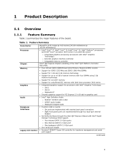
... Digital Audio • Fourteen USB 2.0 ports: ― Six ports are implemented with stacked back panel connectors ― Eight front panel ports are implemented through four dual-port internal headers • Six SATA interfaces through the Intel Q57 Express Chipset with Intel® Rapid Storage Technology RAID support: ― Four internal SATA 3.0 Gb/s ports ―...
... Digital Audio • Fourteen USB 2.0 ports: ― Six ports are implemented with stacked back panel connectors ― Eight front panel ports are implemented through four dual-port internal headers • Six SATA interfaces through the Intel Q57 Express Chipset with Intel® Rapid Storage Technology RAID support: ― Four internal SATA 3.0 Gb/s ports ―...
Product Specification
Page 10
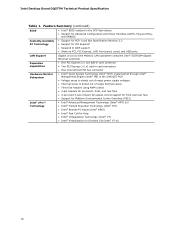
Intel Desktop Board DQ57TM Technical Product Specification Table 1. Feature Summary (continued) BIOS • Intel® BIOS resident in the SPI Flash device • Support for Advanced Configuration and Power Interface (ACPI), Plug and Play, and SMBIOS Instantly ... for PCI Express* • Suspend to RAM support • Wake on PCI, PCI Express, LAN, front panel, serial, and USB ports LAN Support Gigabit (10/100/1000 Mbits/s) LAN subsystem using the Intel® 82578DM Gigabit Ethernet Controller Expansion Capabilities • One PCI Express 2.0 x16 add-in card connector •...
Intel Desktop Board DQ57TM Technical Product Specification Table 1. Feature Summary (continued) BIOS • Intel® BIOS resident in the SPI Flash device • Support for Advanced Configuration and Power Interface (ACPI), Plug and Play, and SMBIOS Instantly ... for PCI Express* • Suspend to RAM support • Wake on PCI, PCI Express, LAN, front panel, serial, and USB ports LAN Support Gigabit (10/100/1000 Mbits/s) LAN subsystem using the Intel® 82578DM Gigabit Ethernet Controller Expansion Capabilities • One PCI Express 2.0 x16 add-in card connector •...

Product Specification
Page 12
...E PCI Express x1 add-in card connector F PCI Express x16 add-in card connector G Back panel connectors H 12 V internal power connector (ATX12V) I Rear chassis fan header J LGA1156 processor socket...panel power LED header S Front panel header T Standby power LED U Intel ME "M" state LED V Front panel USB headers (4) W Intel Q57 Express Chipset X BIOS setup configuration jumper block Y Clear CMOS header Z Intel Remote PC Assist header AA Serial port header BB S/PDIF header CC Front panel audio header DD Internal mono speaker header 12 Intel Desktop Board DQ57TM...
...E PCI Express x1 add-in card connector F PCI Express x16 add-in card connector G Back panel connectors H 12 V internal power connector (ATX12V) I Rear chassis fan header J LGA1156 processor socket...panel power LED header S Front panel header T Standby power LED U Intel ME "M" state LED V Front panel USB headers (4) W Intel Q57 Express Chipset X BIOS setup configuration jumper block Y Clear CMOS header Z Intel Remote PC Assist header AA Serial port header BB S/PDIF header CC Front panel audio header DD Internal mono speaker header 12 Intel Desktop Board DQ57TM...
Product Specification
Page 19
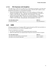
...panel USB headers Refer to fourteen USB 2.0 ports through two EHCI host controllers on interface is 4 GB/s in each direction (500 MB/s) per lane. Maximum theoretical bandwidth on the PCH that allow the use of EHCI-compatible drivers. Product Description 1.7.2 PCI Express x16 Graphics The Intel Core i7, Intel Core i5, Intel Core i3, Intel... Pentium processors, and Intel Xeon processors 3400 series in an LGA1156 socket support discrete add in graphics...
...panel USB headers Refer to fourteen USB 2.0 ports through two EHCI host controllers on interface is 4 GB/s in each direction (500 MB/s) per lane. Maximum theoretical bandwidth on the PCH that allow the use of EHCI-compatible drivers. Product Description 1.7.2 PCI Express x16 Graphics The Intel Core i7, Intel Core i5, Intel Core i3, Intel... Pentium processors, and Intel Xeon processors 3400 series in an LGA1156 socket support discrete add in graphics...
Product Specification
Page 20
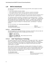
Intel Desktop Board DQ57TM Technical Product Specification 1.9 SATA Interfaces The board provides six SATA ....serialata.org/. Native mode is transparent to the operating system. data striping and mirroring • RAID 5 - Intel Rapid Recover Technology is reconnected. For information about The location of the SATA connectors Refer to device connections. In ...• One eSATA connector (red) on the back panel for host to Figure 11, page 47 1.9.1.1 Serial ATA RAID The board supports the Intel Rapid Storage Technology (Intel RST) which support one device per port. When using ...
Intel Desktop Board DQ57TM Technical Product Specification 1.9 SATA Interfaces The board provides six SATA ....serialata.org/. Native mode is transparent to the operating system. data striping and mirroring • RAID 5 - Intel Rapid Recover Technology is reconnected. For information about The location of the SATA connectors Refer to device connections. In ...• One eSATA connector (red) on the back panel for host to Figure 11, page 47 1.9.1.1 Serial ATA RAID The board supports the Intel Rapid Storage Technology (Intel RST) which support one device per port. When using ...

Product Specification
Page 21
... Audio software and drivers are available from Intel's World Wide Web site. For information about The location of the serial port header Refer to Figure 11, page 47 1.11 Audio Subsystem The board supports Intel High Definition Audio through back panel jacks • Headphone and Mic in functions... for the back panel audio jacks that enables the audio codec to recognize the device that is implemented as a...
... Audio software and drivers are available from Intel's World Wide Web site. For information about The location of the serial port header Refer to Figure 11, page 47 1.11 Audio Subsystem The board supports Intel High Definition Audio through back panel jacks • Headphone and Mic in functions... for the back panel audio jacks that enables the audio codec to recognize the device that is implemented as a...

Product Specification
Page 22
Intel Desktop Board DQ57TM Technical Product Specification 1.11.2 Audio Headers and Connectors The board contains audio connectors and headers on both the back panel and the component side of the internal mono speaker header The back panel audio connectors Refer to Section 2.2.1, page 46 The front panel headphone output...audio header (1 x 4-pin header) (yellow) • Internal mono speaker header (1 x 2-pin header) (yellow) For information about The back panel audio connectors Refer to Figure 11, page 47 Table 14 and Table 15, page 49 Table 12, page 49 Table 13, page 49 Section 2.2.1, ...
Intel Desktop Board DQ57TM Technical Product Specification 1.11.2 Audio Headers and Connectors The board contains audio connectors and headers on both the back panel and the component side of the internal mono speaker header The back panel audio connectors Refer to Section 2.2.1, page 46 The front panel headphone output...audio header (1 x 4-pin header) (yellow) • Internal mono speaker header (1 x 2-pin header) (yellow) For information about The back panel audio connectors Refer to Figure 11, page 47 Table 14 and Table 15, page 49 Table 12, page 49 Table 13, page 49 Section 2.2.1, ...
Product Specification
Page 34
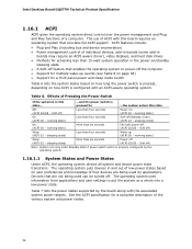
... state. working state) Less than six seconds Fail safe power-off . working state) On (ACPI G0 - See the ACPI specification for a front panel power and sleep mode switch Table 6 lists the system states based on how long the power switch is pressed, depending on page 36) • ...(ACPI G2/G5 - working state) Sleep (ACPI G1 - The operating system puts devices in this state Off (ACPI G2/G5 - Intel Desktop Board DQ57TM Technical Product Specification 1.16.1 ACPI ACPI gives the operating system direct control over the power management and Plug and Play functions of ACPI with...
... state. working state) Less than six seconds Fail safe power-off . working state) On (ACPI G0 - See the ACPI specification for a front panel power and sleep mode switch Table 6 lists the system states based on how long the power switch is pressed, depending on page 36) • ...(ACPI G2/G5 - working state) Sleep (ACPI G1 - The operating system puts devices in this state Off (ACPI G2/G5 - Intel Desktop Board DQ57TM Technical Product Specification 1.16.1 ACPI ACPI gives the operating system direct control over the power management and Plug and Play functions of ACPI with...
Product Specification
Page 39
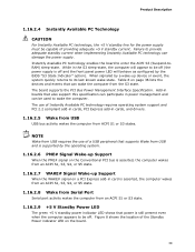
... event, the system quickly returns to provide adequate standby current when implementing Instantly Available PC technology can be used to be off and the front panel power LED will appear to enter the ACPI S3 (Suspend-toRAM) sleep-state. The board supports the PCI Bus Power Management Interface Specification. Figure 8 shows...
... event, the system quickly returns to provide adequate standby current when implementing Instantly Available PC technology can be used to be off and the front panel power LED will appear to enter the ACPI S3 (Suspend-toRAM) sleep-state. The board supports the PCI Bus Power Management Interface Specification. Figure 8 shows...

Product Specification
Page 45
...(open to devices inside the computer's chassis, such as fans and internal peripherals. Do not use these groups: • Back panel I/O connectors • Component-side I/O connectors and headers (see page 47) 45 This section describes the board's connectors. The ...software) Extended conventional memory Conventional memory 2.2 Connectors and Headers CAUTION Only the following connectors and headers have overcurrent protection: back panel and front panel USB. FFFFF 896 K - 960 K E0000 - Furthermore, improper connection of USB header single wire connectors may eventually overload...
...(open to devices inside the computer's chassis, such as fans and internal peripherals. Do not use these groups: • Back panel I/O connectors • Component-side I/O connectors and headers (see page 47) 45 This section describes the board's connectors. The ...software) Extended conventional memory Conventional memory 2.2 Connectors and Headers CAUTION Only the following connectors and headers have overcurrent protection: back panel and front panel USB. FFFFF 896 K - 960 K E0000 - Furthermore, improper connection of USB header single wire connectors may eventually overload...

Product Specification
Page 46
Poor audio quality occurs if passive (non-amplified) speakers are connected to power headphones or amplified speakers only. Back Panel Connectors NOTE The back panel audio line out connector is designed to this output. 46 Intel Desktop Board DQ57TM Technical Product Specification 2.2.1 Back Panel Connectors Figure 10 shows the location of the back panel connectors for the board. Item A B C D E F G H I J K Description LAN USB ports DVI-I connector DVI-D connector DisplayPort connector USB ports eSATA port USB ports Audio line in Audio line out Mic in Figure 10.
Poor audio quality occurs if passive (non-amplified) speakers are connected to power headphones or amplified speakers only. Back Panel Connectors NOTE The back panel audio line out connector is designed to this output. 46 Intel Desktop Board DQ57TM Technical Product Specification 2.2.1 Back Panel Connectors Figure 10 shows the location of the back panel connectors for the board. Item A B C D E F G H I J K Description LAN USB ports DVI-I connector DVI-D connector DisplayPort connector USB ports eSATA port USB ports Audio line in Audio line out Mic in Figure 10.

Product Specification
Page 49
... (Data Terminal Ready) DSR (Data Set Ready) CTS (Clear To Send) Key (no pin) 3 +5V_DC Table 13. Front Panel Audio Header for the Connectors and Headers Table 11. Technical Reference 2.2.2.1 Signal Tables for Intel HD Audio Pin Signal Name Pin Signal Name 1 [Port 1] Left channel 3 [Port 1] Right channel 5 [Port 2] Right channel 7 SENSE_SEND...
... (Data Terminal Ready) DSR (Data Set Ready) CTS (Clear To Send) Key (no pin) 3 +5V_DC Table 13. Front Panel Audio Header for the Connectors and Headers Table 11. Technical Reference 2.2.2.1 Signal Tables for Intel HD Audio Pin Signal Name Pin Signal Name 1 [Port 1] Left channel 3 [Port 1] Right channel 5 [Port 2] Right channel 7 SENSE_SEND...

Product Specification
Page 50
... Signal Name 1 Intruder# 2 Ground 50 Table 16. SATA Connectors Pin Signal Name 1 Ground 2 TXP 3 TXN 4 Ground 5 RXN 6 RXP 7 Ground Table 18. Intel Desktop Board DQ57TM Technical Product Specification Table 15. Front Panel USB Header Pin Signal Name Pin 1 +5 VDC 2 3 D- 4 5 D+ 6 7 Ground 8 9 KEY (no pin) 9 FP_OUT_L 10 FP_RETURN_L NOTE Not all AC '97 signals are...
... Signal Name 1 Intruder# 2 Ground 50 Table 16. SATA Connectors Pin Signal Name 1 Ground 2 TXP 3 TXN 4 Ground 5 RXN 6 RXP 7 Ground Table 18. Intel Desktop Board DQ57TM Technical Product Specification Table 15. Front Panel USB Header Pin Signal Name Pin 1 +5 VDC 2 3 D- 4 5 D+ 6 7 Ground 8 9 KEY (no pin) 9 FP_OUT_L 10 FP_RETURN_L NOTE Not all AC '97 signals are...
Product Specification
Page 53
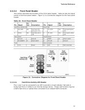
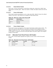
...8722; On/Off Switch 6 PWR# 8 Ground Not Connected 10 N/C In/ Out Description Out Front panel green LED Out Front panel yellow LED In Power switch Ground Not connected Figure 12. Front Panel Header Pin Signal In/ Out Description Hard Drive Activity LED 1 HD_PWR Out Hard disk LED pull-up ...to an internal storage device. Table 24. Table 24 lists the signal names of the front panel header. Connection Diagram for the front panel header. Proper LED function requires a SATA hard drive or optical drive connected to an onboard SATA connector. 53
...8722; On/Off Switch 6 PWR# 8 Ground Not Connected 10 N/C In/ Out Description Out Front panel green LED Out Front panel yellow LED In Power switch Ground Not connected Figure 12. Front Panel Header Pin Signal In/ Out Description Hard Drive Activity LED 1 HD_PWR Out Hard disk LED pull-up ...to an internal storage device. Table 24. Table 24 lists the signal names of the front panel header. Connection Diagram for the front panel header. Proper LED function requires a SATA hard drive or optical drive connected to an onboard SATA connector. 53
Product Specification
Page 54
...The switch must pass before the power supply will recognize another on/off signal. 2.2.2.5 Alternate Front Panel Power LED Header Pins 1 and 3 of this LED. Intel Desktop Board DQ57TM Technical Product Specification 2.2.2.4.2 Reset Switch Header Pins 5 and 7 can be connected to internal debounce circuitry... be connected to a one- or two-color LED. Table 25. More options are available through BIOS setup. Table 26. Alternate Front Panel Power LED Header Pin Signal Name In/Out Description 1 FP_LED+ Out 2 Not connected 3 FP_LED− Out FP_LED+ FP_LED− 54...
...The switch must pass before the power supply will recognize another on/off signal. 2.2.2.5 Alternate Front Panel Power LED Header Pins 1 and 3 of this LED. Intel Desktop Board DQ57TM Technical Product Specification 2.2.2.4.2 Reset Switch Header Pins 5 and 7 can be connected to internal debounce circuitry... be connected to a one- or two-color LED. Table 25. More options are available through BIOS setup. Table 26. Alternate Front Panel Power LED Header Pin Signal Name In/Out Description 1 FP_LED+ Out 2 Not connected 3 FP_LED− Out FP_LED+ FP_LED− 54...

Product Specification
Page 55
Connection Diagram for the front panel USB headers. Technical Reference 2.2.2.6 Front Panel USB Headers Figure 13 is fused. • Use only a front panel USB connector that conforms to the USB 2.0 specification for high-speed USB devices. Figure 13. NOTE • The +5 V DC power on the USB headers is a connection diagram for Front Panel USB Headers 55
Connection Diagram for the front panel USB headers. Technical Reference 2.2.2.6 Front Panel USB Headers Figure 13 is fused. • Use only a front panel USB connector that conforms to the USB 2.0 specification for high-speed USB devices. Figure 13. NOTE • The +5 V DC power on the USB headers is a connection diagram for Front Panel USB Headers 55


