

DP67DE Technical Product Specification
Page 8
Intel Desktop Board DP67DE Technical Product Specification 2 Technical Reference 2.1 Memory Resources 37 2.1.1 Addressable Memory 37 2.1.2 Memory Map 39 2.2 Connectors and Headers 39 2.2.1 Back Panel Connectors 40 2.2.2 Component-side Connectors and Headers 41 2.3 Jumper Block 50 2.4 Mechanical Considerations 52 2.4.1 Form Factor 52 2.5 Electrical Considerations 53 ...Features 66 3.11 BIOS Performance Features 67 4 Error Messages and Beep Codes 4.1 Speaker 69 4.2 BIOS Beep Codes 69 4.3 Front-panel Power LED Blink Codes 70 4.4 BIOS Error Messages 70 4.5 Port 80h POST Codes 71 viii
Intel Desktop Board DP67DE Technical Product Specification 2 Technical Reference 2.1 Memory Resources 37 2.1.1 Addressable Memory 37 2.1.2 Memory Map 39 2.2 Connectors and Headers 39 2.2.1 Back Panel Connectors 40 2.2.2 Component-side Connectors and Headers 41 2.3 Jumper Block 50 2.4 Mechanical Considerations 52 2.4.1 Form Factor 52 2.5 Electrical Considerations 53 ...Features 66 3.11 BIOS Performance Features 67 4 Error Messages and Beep Codes 4.1 Speaker 69 4.2 BIOS Beep Codes 69 4.3 Front-panel Power LED Blink Codes 70 4.4 BIOS Error Messages 70 4.5 Port 80h POST Codes 71 viii

DP67DE Technical Product Specification
Page 9
... 29 7. Connection Diagram for Front Panel USB 2.0 Headers 49 13. Connection Diagram for Front Panel Header 47 12. Components Shown in Figure 10 42 11. LAN Connector LED States 27 6. Front Panel Audio Header for Intel HD Audio 43 13. Location of...Declaration of Pressing the Power Switch 30 7. Major Board Components 13 2. Memory Channel and DIMM Configuration 20 4. Back Panel Audio Connectors 25 5. Back Panel Connectors 40 10. Localized High Temperature Zones 55 Tables 1. Effects of Conformity Statement 78 5.1.3 Product Ecology Statements 79 5.1.4...
... 29 7. Connection Diagram for Front Panel USB 2.0 Headers 49 13. Connection Diagram for Front Panel Header 47 12. Components Shown in Figure 10 42 11. LAN Connector LED States 27 6. Front Panel Audio Header for Intel HD Audio 43 13. Location of...Declaration of Pressing the Power Switch 30 7. Major Board Components 13 2. Memory Channel and DIMM Configuration 20 4. Back Panel Audio Connectors 25 5. Back Panel Connectors 40 10. Localized High Temperature Zones 55 Tables 1. Effects of Conformity Statement 78 5.1.3 Product Ecology Statements 79 5.1.4...
DP67DE Technical Product Specification
Page 10
Intel Desktop Board DP67DE Technical Product Specification 17. Processor Core Power Connector 46 22. Alternate Front Panel Power/Sleep LED Header 48 27. BIOS Setup Configuration Jumper Settings 51 28. Port 80h POST Code Ranges 71 42. Typical Port 80h POST Sequence 76 44. EMC Regulations 81 46. Front Panel... Safety Standards 77 45. Thermal Considerations for BIOS Recovery 63 36. AcceptableDrives/Media Types for Components 56 31. Front-panel Power LED Blink Codes 70 40. Fan Header Current Capability 54 30. Environmental Specifications 57 33. Boot Device Menu ...
Intel Desktop Board DP67DE Technical Product Specification 17. Processor Core Power Connector 46 22. Alternate Front Panel Power/Sleep LED Header 48 27. BIOS Setup Configuration Jumper Settings 51 28. Port 80h POST Code Ranges 71 42. Typical Port 80h POST Sequence 76 44. EMC Regulations 81 46. Front Panel... Safety Standards 77 45. Thermal Considerations for BIOS Recovery 63 36. AcceptableDrives/Media Types for Components 56 31. Front-panel Power LED Blink Codes 70 40. Fan Header Current Capability 54 30. Environmental Specifications 57 33. Boot Device Menu ...
DP67DE Technical Product Specification
Page 11
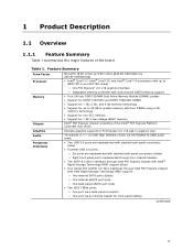
... 1 Gb, 2 Gb, and 4 Gb memory technology • Support for up to 95W TDP in graphics card 10-channel (7.1 + 2) Intel High Definition Audio via the Realtek ALC892 audio codec • Two USB 3.0 ports are implemented with stacked back panel connectors (blue) • Fourteen USB 2.0 ports: ― Six ports are implemented with stacked back...
... 1 Gb, 2 Gb, and 4 Gb memory technology • Support for up to 95W TDP in graphics card 10-channel (7.1 + 2) Intel High Definition Audio via the Realtek ALC892 audio codec • Two USB 3.0 ports are implemented with stacked back panel connectors (blue) • Fourteen USB 2.0 ports: ― Six ports are implemented with stacked back...

DP67DE Technical Product Specification
Page 12
...• Two PCI Express 2.0 x1 add-in card connectors • One Conventional PCI bus connector • Intel® BIOS resident in the SPI Flash device • Support for Advanced Configuration and Power Interface (ACPI), Plug... support • Wake on PCI, PCI Express, LAN, front panel, Consumer Infrared (CIR), and USB ports Gigabit (10/100/1000 Mbits/s) LAN subsystem using the Intel® 82579V Gigabit Ethernet Controller Legacy I/O Control Hardware Monitor Subsystem ... fan activity • Fan speed control 12 Intel Desktop Board DP67DE Technical Product Specification Table 1.
...• Two PCI Express 2.0 x1 add-in card connectors • One Conventional PCI bus connector • Intel® BIOS resident in the SPI Flash device • Support for Advanced Configuration and Power Interface (ACPI), Plug... support • Wake on PCI, PCI Express, LAN, front panel, Consumer Infrared (CIR), and USB ports Gigabit (10/100/1000 Mbits/s) LAN subsystem using the Intel® 82579V Gigabit Ethernet Controller Legacy I/O Control Hardware Monitor Subsystem ... fan activity • Fan speed control 12 Intel Desktop Board DP67DE Technical Product Specification Table 1.

DP67DE Technical Product Specification
Page 14
... PCI Express x1 add-in card connector IEEE 1394a front panel header PCI Express x1 bus add-in card connector PCI Express x16 bus add-in Figure 1. Table 2. Intel Desktop Board DP67DE Technical Product Specification Table 2 lists the components identified in ...card connector Back panel connectors Processor core power connector (2 x 2) Rear chassis fan header LGA1155 processor socket Processor fan ...
... PCI Express x1 add-in card connector IEEE 1394a front panel header PCI Express x1 bus add-in card connector PCI Express x16 bus add-in Figure 1. Table 2. Intel Desktop Board DP67DE Technical Product Specification Table 2 lists the components identified in ...card connector Back panel connectors Processor core power connector (2 x 2) Rear chassis fan header LGA1155 processor socket Processor fan ...

DP67DE Technical Product Specification
Page 21
... centralized controller for the 2.0 ports. The Intel P67 Express Chipset provides the USB controller for the board's I/O paths. For information about The location of the USB connectors on the back panel The location of the front panel USB headers Refer to 14 USB 2.0 ports...Media Interface (DMI) interconnect provides interfaces to the cable. Product Description 1.6 Intel® P67 Express Chipset Intel P67 Express Chipset with stacked back panel connectors (black) • Eight USB 2.0 front panel ports implemented through four internal headers All 16 USB ports are high-speed, ...
... centralized controller for the 2.0 ports. The Intel P67 Express Chipset provides the USB controller for the board's I/O paths. For information about The location of the USB connectors on the back panel The location of the front panel USB headers Refer to 14 USB 2.0 ports...Media Interface (DMI) interconnect provides interfaces to the cable. Product Description 1.6 Intel® P67 Express Chipset Intel P67 Express Chipset with stacked back panel connectors (black) • Eight USB 2.0 front panel ports implemented through four internal headers All 16 USB ports are high-speed, ...

DP67DE Technical Product Specification
Page 22
... mode, standard PCI Conventional bus resource steering is transparent to the operating system. Intel Desktop Board DP67DE Technical Product Specification 1.7 SATA Interfaces The board provides six SATA connectors through the PCH..., which support one device per connector: • Two internal SATA 6.0 Gb/s connectors (blue) • Two internal SATA 3.0 Gb/s connectors (black) • One internal eSATA 3.0 Gb/s connector (red) • One eSATA 3.0 Gb/s connector on the back panel...
... mode, standard PCI Conventional bus resource steering is transparent to the operating system. Intel Desktop Board DP67DE Technical Product Specification 1.7 SATA Interfaces The board provides six SATA connectors through the PCH..., which support one device per connector: • Two internal SATA 6.0 Gb/s connectors (blue) • Two internal SATA 3.0 Gb/s connectors (black) • One internal eSATA 3.0 Gb/s connector (red) • One eSATA 3.0 Gb/s connector on the back panel...

DP67DE Technical Product Specification
Page 24
... Rear Black Rear Orange Front Speaker Default Line In Default Rear Center/ Surround Sub Default Default Side Surround Ctrl panel 24 Intel Desktop Board DP67DE Technical Product Specification 1.9.1 Consumer Infrared (CIR) The Consumer Infrared (CIR) feature is connected to an audio port.... This learning input is made up of the front panel and back panel audio jacks. Customers are the supported operating systems. The CIR...
... Rear Black Rear Orange Front Speaker Default Line In Default Rear Center/ Surround Sub Default Default Side Surround Ctrl panel 24 Intel Desktop Board DP67DE Technical Product Specification 1.9.1 Consumer Infrared (CIR) The Consumer Infrared (CIR) feature is connected to an audio port.... This learning input is made up of the front panel and back panel audio jacks. Customers are the supported operating systems. The CIR...

DP67DE Technical Product Specification
Page 25
... 1.10.1 Audio Subsystem Software The latest audio software and drivers are shown in Figure 4. The available configurable back panel audio connectors are available from Intel's World Wide Web site. For information about Obtaining audio software and drivers Refer to Section 1.3, page 16 1.10....2 Audio Subsystem Components The audio subsystem includes the following components: • Intel H67 Express Chipset • Realtek ALC892 audio codec • Front panel audio header that supports Intel HD audio and AC '97 audio (a 2 x 5-pin header that provides mic in /side...
... 1.10.1 Audio Subsystem Software The latest audio software and drivers are shown in Figure 4. The available configurable back panel audio connectors are available from Intel's World Wide Web site. For information about Obtaining audio software and drivers Refer to Section 1.3, page 16 1.10....2 Audio Subsystem Components The audio subsystem includes the following components: • Intel H67 Express Chipset • Realtek ALC892 audio codec • Front panel audio header that supports Intel HD audio and AC '97 audio (a 2 x 5-pin header that provides mic in /side...

DP67DE Technical Product Specification
Page 26
Intel Desktop Board DP67DE Technical Product Specification NOTE The back panel audio line out connector is designed to this output. Poor audio quality occurs if passive (non-amplified) speakers are connected to power headphones or amplified speakers only. For information about The locations of the front panel... names of the front panel audio header and S/PDIF audio header The back panel audio connectors Refer to Figure 10, page 41 Section 2.2.2.1, page 43 Section 2.2.1, page 40 1.11 LAN Subsystem The LAN subsystem consists of the following: • Intel 82579V Gigabit Ethernet Controller ...
Intel Desktop Board DP67DE Technical Product Specification NOTE The back panel audio line out connector is designed to this output. Poor audio quality occurs if passive (non-amplified) speakers are connected to power headphones or amplified speakers only. For information about The locations of the front panel... names of the front panel audio header and S/PDIF audio header The back panel audio connectors Refer to Figure 10, page 41 Section 2.2.2.1, page 43 Section 2.2.1, page 40 1.11 LAN Subsystem The LAN subsystem consists of the following: • Intel 82579V Gigabit Ethernet Controller ...

DP67DE Technical Product Specification
Page 30
Intel Desktop Board DP67DE Technical Product Specification 1.13 Power Management Power management is implemented at several levels, including: • Software support through Advanced Configuration and Power Interface (ACPI) • ... ACPI support. Table 6. Effects of a computer. sleeping state) Sleep (ACPI G1 - Soft off) Wake-up events (see Table 8 on page 32) • Support for a front panel power and sleep mode switch Table 6 lists the system states based on how long the power switch is pressed, depending on (ACPI G0 - Soft off...
Intel Desktop Board DP67DE Technical Product Specification 1.13 Power Management Power management is implemented at several levels, including: • Software support through Advanced Configuration and Power Interface (ACPI) • ... ACPI support. Table 6. Effects of a computer. sleeping state) Sleep (ACPI G1 - Soft off) Wake-up events (see Table 8 on page 32) • Support for a front panel power and sleep mode switch Table 6 lists the system states based on how long the power switch is pressed, depending on (ACPI G0 - Soft off...

DP67DE Technical Product Specification
Page 34
... the power supply. Add-in the S3 sleep-state, the computer will appear to be off (the power supply is off, and the front panel LED is amber if dual colored, or off if single colored.) When signaled by a wake-up device or event, the system quickly returns to... wake the computer. Depending on page 32 lists the devices and events that also support this specification can participate in cards, and drivers. 34 Intel Desktop Board DP67DE Technical Product Specification 1.13.2.3 LAN Wake Capabilities CAUTION For LAN wake capabilities, the +5 V standby line for the power supply must be capable...
... the power supply. Add-in the S3 sleep-state, the computer will appear to be off (the power supply is off, and the front panel LED is amber if dual colored, or off if single colored.) When signaled by a wake-up device or event, the system quickly returns to... wake the computer. Depending on page 32 lists the devices and events that also support this specification can participate in cards, and drivers. 34 Intel Desktop Board DP67DE Technical Product Specification 1.13.2.3 LAN Wake Capabilities CAUTION For LAN wake capabilities, the +5 V standby line for the power supply must be capable...

DP67DE Technical Product Specification
Page 39
... could cause damage to the computer, the power cable, and the external devices themselves. Do not use these groups: • Back panel I/O connectors • Component-side I/O connectors and headers (see page 41) 39 A fault in the load presented by memory manager software...) Extended conventional memory Conventional memory 2.2 Connectors and Headers CAUTION Only the following connectors and headers have overcurrent protection: back panel and front panel USB, as well as fans and internal peripherals. EFFFF 800 K - 896 K C8000 - Furthermore, improper connection of USB or...
... could cause damage to the computer, the power cable, and the external devices themselves. Do not use these groups: • Back panel I/O connectors • Component-side I/O connectors and headers (see page 41) 39 A fault in the load presented by memory manager software...) Extended conventional memory Conventional memory 2.2 Connectors and Headers CAUTION Only the following connectors and headers have overcurrent protection: back panel and front panel USB, as well as fans and internal peripherals. EFFFF 800 K - 896 K C8000 - Furthermore, improper connection of USB or...

DP67DE Technical Product Specification
Page 40
... NOTE The back panel audio line out connector is designed to this output. 40 Item A B C D E F G H I J K L M Description USB 2.0 ports eSATA connector LAN port USB 2.0 ports USB 2.0 ports IEEE 1394a connector .../side surround Line out/front speakers Figure 9. Poor audio quality occurs if passive (non-amplified) speakers are connected to power headphones or amplified speakers only. Intel Desktop Board DP67DE Technical Product Specification 2.2.1 Back Panel Connectors Figure 9 shows the location of the back...
... NOTE The back panel audio line out connector is designed to this output. 40 Item A B C D E F G H I J K L M Description USB 2.0 ports eSATA connector LAN port USB 2.0 ports USB 2.0 ports IEEE 1394a connector .../side surround Line out/front speakers Figure 9. Poor audio quality occurs if passive (non-amplified) speakers are connected to power headphones or amplified speakers only. Intel Desktop Board DP67DE Technical Product Specification 2.2.1 Back Panel Connectors Figure 9 shows the location of the back...

DP67DE Technical Product Specification
Page 42
Intel Desktop Board DP67DE Technical Product Specification Table 10 lists the component-side connectors and headers identified in card connector F Processor core power connector (2 x 2) G Rear ... IR receiver (input) header N Main power connector (2 X 12) O SATA connectors P Front panel header Q Alternate front panel power LED header R Front panel USB 2.0 header S Front panel USB 2.0 header T Front panel USB 2.0 header U Front panel USB 2.0 header V S/PDIF out header W Front panel audio header 42 Table 10. Component-side Connectors and Headers Shown in Figure 10...
Intel Desktop Board DP67DE Technical Product Specification Table 10 lists the component-side connectors and headers identified in card connector F Processor core power connector (2 x 2) G Rear ... IR receiver (input) header N Main power connector (2 X 12) O SATA connectors P Front panel header Q Alternate front panel power LED header R Front panel USB 2.0 header S Front panel USB 2.0 header T Front panel USB 2.0 header U Front panel USB 2.0 header V S/PDIF out header W Front panel audio header 42 Table 10. Component-side Connectors and Headers Shown in Figure 10...

DP67DE Technical Product Specification
Page 43
... 3 MIC_BIAS 4 AUD_GND 5 FP_OUT_R 6 FP_RETURN_R 7 AUD_5V 8 KEY (no pin) Pin 2 4 6 8 10 Signal Name Data A (negative) Ground Data B (negative) +12 V DC Ground Table 12. Front Panel Audio Header for Intel HD Audio Pin Signal Name Pin Signal Name 1 [Port 1] Left channel 2 Ground 3 [Port 1] Right channel 4 PRESENCE# (Dongle present) 5 [Port 2] Right channel 6 [Port 1] SENSE_RETURN 7 SENSE_SEND...
... 3 MIC_BIAS 4 AUD_GND 5 FP_OUT_R 6 FP_RETURN_R 7 AUD_5V 8 KEY (no pin) Pin 2 4 6 8 10 Signal Name Data A (negative) Ground Data B (negative) +12 V DC Ground Table 12. Front Panel Audio Header for Intel HD Audio Pin Signal Name Pin Signal Name 1 [Port 1] Left channel 2 Ground 3 [Port 1] Right channel 4 PRESENCE# (Dongle present) 5 [Port 2] Right channel 6 [Port 1] SENSE_RETURN 7 SENSE_SEND...

DP67DE Technical Product Specification
Page 44
... Chassis (4-Pin) Fan Headers Pin Signal Name 1 Ground (Note) 2 +12 V 3 FAN_TACH 4 FAN_CONTROL Note: These fan headers use Pulse Width Modulation control for fan speed. Back Panel CIR Emitter (Output) Header Pin Signal Name 1 Emitter out 1 2 Emitter out 2 3 Ground 4 Key (no pin) 4 +5 V DC Table 17. S/PDIF Header Pin Signal Name 1 Ground 2 S/PDIF...
... Chassis (4-Pin) Fan Headers Pin Signal Name 1 Ground (Note) 2 +12 V 3 FAN_TACH 4 FAN_CONTROL Note: These fan headers use Pulse Width Modulation control for fan speed. Back Panel CIR Emitter (Output) Header Pin Signal Name 1 Emitter out 1 2 Emitter out 2 3 Ground 4 Key (no pin) 4 +5 V DC Table 17. S/PDIF Header Pin Signal Name 1 Ground 2 S/PDIF...

DP67DE Technical Product Specification
Page 45
... 2.0 x16 connector supporting simultaneous transfer speeds up to 8 GB/s of peak bandwidth per direction and up to access sensor data on the desktop board. Front Panel CIR Receiver (Input) Header Pin Signal Name 1 Ground 2 LED 3 NC 4 Learn-in 5 5 V standby 6 VCC 7 Key (no pin) 8 CIR Input 2.2.2.2 Add-in Card Connectors The board...
... 2.0 x16 connector supporting simultaneous transfer speeds up to 8 GB/s of peak bandwidth per direction and up to access sensor data on the desktop board. Front Panel CIR Receiver (Input) Header Pin Signal Name 1 Ground 2 LED 3 NC 4 Learn-in 5 5 V standby 6 VCC 7 Key (no pin) 8 CIR Input 2.2.2.2 Add-in Card Connectors The board...

DP67DE Technical Product Specification
Page 47
... Ground 7 RESET_SWITCH# [In] Reset switch 9 +5V_DC Power Pin Signal Name 2 POWER_LED_MAIN 4 POWER_LED_ALT 6 POWER_SWITCH# 8 GROUND 10 Key Description [Out] Front panel LED (main color) [Out] Front panel LED (alt color) [In] Power switch Ground No pin Figure 11. Table 23 lists the signal names of the front... panel header. Table 23. Front Panel Header Pin Signal Name Description 1 HDD_POWER_LED Pull-up resistor (750 Ω) to a momentary single pole, single throw (SPST...
... Ground 7 RESET_SWITCH# [In] Reset switch 9 +5V_DC Power Pin Signal Name 2 POWER_LED_MAIN 4 POWER_LED_ALT 6 POWER_SWITCH# 8 GROUND 10 Key Description [Out] Front panel LED (main color) [Out] Front panel LED (alt color) [In] Power switch Ground No pin Figure 11. Table 23 lists the signal names of the front... panel header. Table 23. Front Panel Header Pin Signal Name Description 1 HDD_POWER_LED Pull-up resistor (750 Ω) to a momentary single pole, single throw (SPST...


