

DP67DE Technical Product Specification
Page 8
Intel Desktop Board DP67DE Technical Product Specification 2 Technical Reference 2.1 Memory Resources 37 2.1.1 Addressable Memory 37 2.1.2 Memory Map 39 2.2 Connectors and Headers 39 2.2.1... 2.7 Reliability 57 2.8 Environmental 57 3 Overview of BIOS Features 3.1 Introduction 59 3.2 BIOS Flash Memory Organization 60 3.3 Resource Configuration 60 3.3.1 PCI Autoconfiguration 60 3.4 System Management BIOS (SMBIOS 61 3.5 Legacy USB Support 61 3.6 BIOS Updates 62 3.6.1 Language Support 62 3.6.2 Custom Splash Screen 63 3.7 BIOS Recovery 63 3.8 Boot Options 64 3.8.1 Optical Drive Boot ...
Intel Desktop Board DP67DE Technical Product Specification 2 Technical Reference 2.1 Memory Resources 37 2.1.1 Addressable Memory 37 2.1.2 Memory Map 39 2.2 Connectors and Headers 39 2.2.1... 2.7 Reliability 57 2.8 Environmental 57 3 Overview of BIOS Features 3.1 Introduction 59 3.2 BIOS Flash Memory Organization 60 3.3 Resource Configuration 60 3.3.1 PCI Autoconfiguration 60 3.4 System Management BIOS (SMBIOS 61 3.5 Legacy USB Support 61 3.6 BIOS Updates 62 3.6.1 Language Support 62 3.6.2 Custom Splash Screen 63 3.7 BIOS Recovery 63 3.8 Boot Options 64 3.8.1 Optical Drive Boot ...
DP67DE Technical Product Specification
Page 10
...Boot Device Menu Options 64 37. Front-panel Power LED Blink Codes 70 40. Front Panel Header 47 24. BIOS Beep Codes 69 39. BIOS Error Messages 70 41. Typical Port 80h POST Sequence 76 44. Chassis Intrusion Header 44 18. Main Power Connector... for Components 56 32. Intel Desktop Board DP67DE Technical Product Specification 17. Processor Core Power Connector 46 22. Recommended Power Supply Current Values 53 29. Fan Header Current Capability 54 30. Environmental Specifications 57 33. AcceptableDrives/Media Types for BIOS Recovery 63 36. Port 80h ...
...Boot Device Menu Options 64 37. Front-panel Power LED Blink Codes 70 40. Front Panel Header 47 24. BIOS Beep Codes 69 39. BIOS Error Messages 70 41. Typical Port 80h POST Sequence 76 44. Chassis Intrusion Header 44 18. Main Power Connector... for Components 56 32. Intel Desktop Board DP67DE Technical Product Specification 17. Processor Core Power Connector 46 22. Recommended Power Supply Current Values 53 29. Fan Header Current Capability 54 30. Environmental Specifications 57 33. AcceptableDrives/Media Types for BIOS Recovery 63 36. Port 80h ...

DP67DE Technical Product Specification
Page 50
... program's mode. When the jumper is set to configure mode and the computer is powered-up, the BIOS compares the processor version and the microcode version in the BIOS and reports if the two match. Figure 13. Location of the jumper block. Always turn off the power ...a jumper setting. Otherwise, the board could be damaged. Table 28 describes the jumper settings for the three modes: normal, configure, and recovery. Intel Desktop Board DP67DE Technical Product Specification 2.3 Jumper Block CAUTION Do not move the jumper with the power on. Figure 13 shows the location of the Jumper ...
... program's mode. When the jumper is set to configure mode and the computer is powered-up, the BIOS compares the processor version and the microcode version in the BIOS and reports if the two match. Figure 13. Location of the jumper block. Always turn off the power ...a jumper setting. Otherwise, the board could be damaged. Table 28 describes the jumper settings for the three modes: normal, configure, and recovery. Intel Desktop Board DP67DE Technical Product Specification 2.3 Jumper Block CAUTION Do not move the jumper with the power on. Figure 13 shows the location of the Jumper ...

DP67DE Technical Product Specification
Page 51
... defaults) while in Configure mode to restore the BIOS/CMOS settings to clear the BIOS/CMOS settings. BIOS Setup Configuration Jumper Settings Function/Mode Normal Jumper Setting 1-2 Configuration The BIOS uses current configuration information and passwords for booting. Configure 2-3 Recovery None After the POST runs, Setup runs automatically. A recovery CD or flash drive is displayed. The...
... defaults) while in Configure mode to restore the BIOS/CMOS settings to clear the BIOS/CMOS settings. BIOS Setup Configuration Jumper Settings Function/Mode Normal Jumper Setting 1-2 Configuration The BIOS uses current configuration information and passwords for booting. Configure 2-3 Recovery None After the POST runs, Setup runs automatically. A recovery CD or flash drive is displayed. The...

DP67DE Technical Product Specification
Page 63
...a custom splash screen, it will interrupt a BIOS update; Table 36. For information about BIOS recovery Refer to be used for BIOS Recovery Media Type Can be made bootable. The BIOS recovery media does not need to http://www.intel.com/support/motherboards/desktop/sb /cs-023360.htm ... No USB hard disk drive No For information about Intel Integrator Toolkit Additional Intel® software tools Refer to http://developer.intel.com/design/motherbd/software/itk/ http://developer.intel.com/design/motherbd/software.htm 3.7 BIOS Recovery It is unlikely that can be used to the SATA...
...a custom splash screen, it will interrupt a BIOS update; Table 36. For information about BIOS recovery Refer to be used for BIOS Recovery Media Type Can be made bootable. The BIOS recovery media does not need to http://www.intel.com/support/motherboards/desktop/sb /cs-023360.htm ... No USB hard disk drive No For information about Intel Integrator Toolkit Additional Intel® software tools Refer to http://developer.intel.com/design/motherbd/software/itk/ http://developer.intel.com/design/motherbd/software.htm 3.7 BIOS Recovery It is unlikely that can be used to the SATA...
DP67DE Technical Product Specification
Page 71
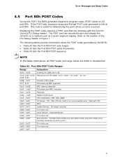
...Security (SEC) phase 0x11 0x1F 0x21 - 0x29 0x2A - 0x2F 0x31 - 0x35 PEI phase pre MRC execution MRC memory detection PEI phase post MRC execution Recovery 0x36 - 0x3F Platform DXE driver 0x41 - 0x4F CPU Initialization (PEI, DXE, SMM) 0x50 - 0x5F I /O port 80h. Error Messages and Beep Codes... 4.5 Port 80h POST Codes During the POST, the BIOS generates diagnostic progress codes (POST codes) to I /O Buses: PCI, USB, ATA etc. 0x5F is an unrecoverable error. The following tables provide information ...
...Security (SEC) phase 0x11 0x1F 0x21 - 0x29 0x2A - 0x2F 0x31 - 0x35 PEI phase pre MRC execution MRC memory detection PEI phase post MRC execution Recovery 0x36 - 0x3F Platform DXE driver 0x41 - 0x4F CPU Initialization (PEI, DXE, SMM) 0x50 - 0x5F I /O port 80h. Error Messages and Beep Codes... 4.5 Port 80h POST Codes During the POST, the BIOS generates diagnostic progress codes (POST codes) to I /O Buses: PCI, USB, ATA etc. 0x5F is an unrecoverable error. The following tables provide information ...

DP67DE Technical Product Specification
Page 76
Intel Desktop Board DP67DE Technical Product Specification Table 44. Typical Port 80h POST Sequence POST Code Description 21 Initializing a chipset component 22 Reading SPD from memory DIMMs 23 Detecting presence of memory DIMMs 25 Configuring memory 28 Testing memory 34 Loading recovery capsule E4 Entered DXE phase 12 Starting application processor initialization 13 SMM...
Intel Desktop Board DP67DE Technical Product Specification Table 44. Typical Port 80h POST Sequence POST Code Description 21 Initializing a chipset component 22 Reading SPD from memory DIMMs 23 Detecting presence of memory DIMMs 25 Configuring memory 28 Testing memory 34 Loading recovery capsule E4 Entered DXE phase 12 Starting application processor initialization 13 SMM...
English Product Guide
Page 51
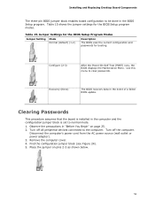
... booting. Jumper Settings for the BIOS Setup Program Modes Jumper Setting Mode Normal (default) (1-2) Description The BIOS uses the current configuration and passwords for the BIOS Setup program modes. Remove the ... to the computer. Configure (2-3) After the Power-On Self-Test (POST) runs, the BIOS displays the Maintenance Menu. Find the configuration jumper block (see Figure 24). 5. Observe the... and Replacing Desktop Board Components The three-pin BIOS jumper block enables board configuration to be done in the event of a failed BIOS update. Use this menu to clear passwords. ...
... booting. Jumper Settings for the BIOS Setup Program Modes Jumper Setting Mode Normal (default) (1-2) Description The BIOS uses the current configuration and passwords for the BIOS Setup program modes. Remove the ... to the computer. Configure (2-3) After the Power-On Self-Test (POST) runs, the BIOS displays the Maintenance Menu. Find the configuration jumper block (see Figure 24). 5. Observe the... and Replacing Desktop Board Components The three-pin BIOS jumper block enables board configuration to be done in the event of a failed BIOS update. Use this menu to clear passwords. ...

English Product Guide
Page 60
..., press F7 to save the Recovery BIOS (.BIO) file to the Advanced > Boot Configuration menu. Copy the .BIO to complete. 11. Enter the BIOS Setup by pressing Enter. 10. Remove the thumb drive. 12. Wait 2-5 minutes for the update to a USB thumb drive. 3. Intel Desktop Board DP67DE Product Guide Updating the BIOS Using the F7 Function Key To...
..., press F7 to save the Recovery BIOS (.BIO) file to the Advanced > Boot Configuration menu. Copy the .BIO to complete. 11. Enter the BIOS Setup by pressing Enter. 10. Remove the thumb drive. 12. Wait 2-5 minutes for the update to a USB thumb drive. 3. Intel Desktop Board DP67DE Product Guide Updating the BIOS Using the F7 Function Key To...

English Product Guide
Page 63
... about updating the Intel Desktop Board BIOS or recovering from a BIOS update failure, go to the Intel Desktop Board DP67DE page on the "BIOS Update" link and then select the Recovery BIOS Update file. however, if an interruption occurs, the BIOS could be required. The update may take up to BIOS size and recovery requirements, a CD-R with the .BIO file in the...
... about updating the Intel Desktop Board BIOS or recovering from a BIOS update failure, go to the Intel Desktop Board DP67DE page on the "BIOS Update" link and then select the Recovery BIOS Update file. however, if an interruption occurs, the BIOS could be required. The update may take up to BIOS size and recovery requirements, a CD-R with the .BIO file in the...

Simplified Chinese Product Guide
Page 60
DP67DE 使用 F7 BIOS BIOS 1. 下载 Recovery BIOS (.BIO 2. 将 .BIO 复制到 USB 闪盘(U 盘)。 3 USB 端口。 4 5. 启用 F7 a b F2 BIOS Setup c Advanced Boot Configuration d. 启用 Display F7 to Update BIOS(显示 F7 BIOS)。 e. 按 F10 6 F7 F7 键进入 BIOS Flash Update(BIOS 7. 选...
DP67DE 使用 F7 BIOS BIOS 1. 下载 Recovery BIOS (.BIO 2. 将 .BIO 复制到 USB 闪盘(U 盘)。 3 USB 端口。 4 5. 启用 F7 a b F2 BIOS Setup c Advanced Boot Configuration d. 启用 Display F7 to Update BIOS(显示 F7 BIOS)。 e. 按 F10 6 F7 F7 键进入 BIOS Flash Update(BIOS 7. 选...


