
Smart Response Technology User Guide
Page 1
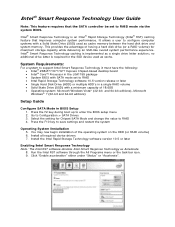
... support Intel Smart Response Technology it must have the following: • Intel® Z68/Z77/H77/Q77 Express Chipset-based desktop board • Intel® Core™ Processor in the LGA1155 package • System BIOS with SATA mode set to RAID mode via the system BIOS. Press the F2 key during boot up to RAID • Intel Rapid Storage Technology software 10.5 version release or later • Single Hard Disk Drive (HDD) or multiple HDD's in BIOS Setup 1. You may now begin installation of having a hard disk drive...
... support Intel Smart Response Technology it must have the following: • Intel® Z68/Z77/H77/Q77 Express Chipset-based desktop board • Intel® Core™ Processor in the LGA1155 package • System BIOS with SATA mode set to RAID mode via the system BIOS. Press the F2 key during boot up to RAID • Intel Rapid Storage Technology software 10.5 version release or later • Single Hard Disk Drive (HDD) or multiple HDD's in BIOS Setup 1. You may now begin installation of having a hard disk drive...
Technical Product Specification
Page 8
...3.5 Legacy USB Support 69 3.6 BIOS Updates 70 3.6.1 Language Support 70 3.6.2 Custom Splash Screen 71 3.7 BIOS Recovery 71 3.8 Boot Options 72 3.8.1 Optical Drive Boot 72 3.8.2 Network Boot 72 3.8.3 Booting Without Attached Devices 72 3.8.4 Changing the Default Boot Device During POST 72 3.9 Adjusting Boot Speed 73 3.9.1 Peripheral Selection and Configuration 73 3.9.2 BIOS Boot Optimizations 73 3.10 BIOS Security Features 74 3.11 BIOS Performance Features 75 4 Error Messages and Beep Codes 4.1 Speaker 77 4.2 BIOS Beep Codes 77 4.3 Front-panel Power LED Blink Codes 77 4.4 BIOS...
...3.5 Legacy USB Support 69 3.6 BIOS Updates 70 3.6.1 Language Support 70 3.6.2 Custom Splash Screen 71 3.7 BIOS Recovery 71 3.8 Boot Options 72 3.8.1 Optical Drive Boot 72 3.8.2 Network Boot 72 3.8.3 Booting Without Attached Devices 72 3.8.4 Changing the Default Boot Device During POST 72 3.9 Adjusting Boot Speed 73 3.9.1 Peripheral Selection and Configuration 73 3.9.2 BIOS Boot Optimizations 73 3.10 BIOS Security Features 74 3.11 BIOS Performance Features 75 4 Error Messages and Beep Codes 4.1 Speaker 77 4.2 BIOS Beep Codes 77 4.3 Front-panel Power LED Blink Codes 77 4.4 BIOS...
Technical Product Specification
Page 9
... Fan Headers 33 7. Component-side Connectors and Headers 45 11. Location of the Standby Power LED 40 8. Intel Desktop Board DH77KC China RoHS Material Self Declaration Table 90 Tables 1. HDMI Port Status Conditions 23 6. Audio Jack Support 28 9. Block Diagram 15 3. Memory Channel and DIMM Configuration 21 4. Components Shown in Figure 10 46 15. DisplayPort Status Conditions 24 7. Front Panel Audio Header for Front Panel USB 2.0 Headers 57 13. Chassis Intrusion Header 49 ix LAN Connector LED Locations 31 6. Detailed System Memory...
... Fan Headers 33 7. Component-side Connectors and Headers 45 11. Location of the Standby Power LED 40 8. Intel Desktop Board DH77KC China RoHS Material Self Declaration Table 90 Tables 1. HDMI Port Status Conditions 23 6. Audio Jack Support 28 9. Block Diagram 15 3. Memory Channel and DIMM Configuration 21 4. Components Shown in Figure 10 46 15. DisplayPort Status Conditions 24 7. Front Panel Audio Header for Front Panel USB 2.0 Headers 57 13. Chassis Intrusion Header 49 ix LAN Connector LED Locations 31 6. Detailed System Memory...
Technical Product Specification
Page 10
.... Port 80h POST Codes 80 52. EMC Regulations 91 55. LPC Debug Header 52 29. Alternate Front Panel Power/Sleep LED Header 56 35. Recommended Power Supply Current Values (High Power 61 37. Environmental Specifications 65 42. Serial Port Header 52 28. Typical Port 80h POST Sequence 84 53. Processor, Front, and Rear Chassis (4-Pin) Fan Headers 49 23. Thermal Considerations for Components 64 40. Intel Desktop Board DH77KC Technical Product Specification 22. Front Panel CIR Receiver (Input) Header 49 25. Boot Device Menu Options...
.... Port 80h POST Codes 80 52. EMC Regulations 91 55. LPC Debug Header 52 29. Alternate Front Panel Power/Sleep LED Header 56 35. Recommended Power Supply Current Values (High Power 61 37. Environmental Specifications 65 42. Serial Port Header 52 28. Typical Port 80h POST Sequence 84 53. Processor, Front, and Rear Chassis (4-Pin) Fan Headers 49 23. Thermal Considerations for Components 64 40. Intel Desktop Board DH77KC Technical Product Specification 22. Front Panel CIR Receiver (Input) Header 49 25. Boot Device Menu Options...
Technical Product Specification
Page 12
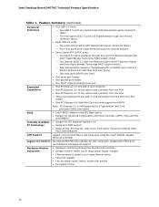
... Card slot with support for mSATA Note: PCI Express 3.0 is only supported by 3rd generation Intel Core processor family processors • Intel® BIOS resident in the SPI Flash device • Support for Advanced Configuration and Power Interface (ACPI), Plug and Play, and SMBIOS • Support for PCI Express* Revision 3.0 • Suspend to RAM support • Wake on PCI, PCI Express, LAN, serial, front panel, Consumer Infrared (CIR), PS/2, and USB ports LAN Support Gigabit (10/100/1000 Mb/s) LAN subsystem using the Intel® 82579V Gigabit Ethernet Controller Legacy I/O Control...
... Card slot with support for mSATA Note: PCI Express 3.0 is only supported by 3rd generation Intel Core processor family processors • Intel® BIOS resident in the SPI Flash device • Support for Advanced Configuration and Power Interface (ACPI), Plug and Play, and SMBIOS • Support for PCI Express* Revision 3.0 • Suspend to RAM support • Wake on PCI, PCI Express, LAN, serial, front panel, Consumer Infrared (CIR), PS/2, and USB ports LAN Support Gigabit (10/100/1000 Mb/s) LAN subsystem using the Intel® 82579V Gigabit Ethernet Controller Legacy I/O Control...
Technical Product Specification
Page 14
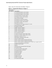
...) Main power connector (2 x 12) BIOS Setup configuration jumper block Intel H77 Express Chipset SATA 6.0 Gb/s connector through the PCH (blue) SATA 3.0 Gb/s connector through the PCH (black) SATA 3.0 Gb/s connector (multiplexed with an mSATA port, routed to the PCI Express Full-/Half-Mini Card slot) (gray) Chassis intrusion header Battery Alternate front panel power/sleep LED header Front panel header Low Pin Count (LPC) Debug header Front panel USB 2.0 connectors Piezoelectric speaker Parallel port header Serial port header Power fault LED Standby power LED S/PDIF out header Front panel audio...
...) Main power connector (2 x 12) BIOS Setup configuration jumper block Intel H77 Express Chipset SATA 6.0 Gb/s connector through the PCH (blue) SATA 3.0 Gb/s connector through the PCH (black) SATA 3.0 Gb/s connector (multiplexed with an mSATA port, routed to the PCI Express Full-/Half-Mini Card slot) (gray) Chassis intrusion header Battery Alternate front panel power/sleep LED header Front panel header Low Pin Count (LPC) Debug header Front panel USB 2.0 connectors Piezoelectric speaker Parallel port header Serial port header Power fault LED Standby power LED S/PDIF out header Front panel audio...
Technical Product Specification
Page 19
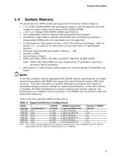
... the option to raise the voltage to support higher performance DDR3 SDRAM DIMMs. • 1.35 V Low Voltage DDR3 DIMMs (JEDEC specification) • Two independent memory channels with interleaved mode support • Unbuffered, single-sided or double-sided DIMMs with the following restriction: Double-sided DIMMs with x16 organization are only supported by 3rd generation Intel Core processor family processors • XMP version 1.3 performance profile support for...
... the option to raise the voltage to support higher performance DDR3 SDRAM DIMMs. • 1.35 V Low Voltage DDR3 DIMMs (JEDEC specification) • Two independent memory channels with interleaved mode support • Unbuffered, single-sided or double-sided DIMMs with the following restriction: Double-sided DIMMs with x16 organization are only supported by 3rd generation Intel Core processor family processors • XMP version 1.3 performance profile support for...
Technical Product Specification
Page 24
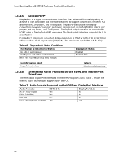
... PCI Express x16 Connector Status No add-in card installed PCI Express x16 add-in card installed Note: May require BIOS setup menu changes. Audio Formats Supported by the PCH. The DisplayPort interface supports the 1.1a specification. The maximum bandwidth is suitable for display connections between PCs and monitors, projectors, and TV displays. DisplayPort is 8.64 Gb/s. Table 6. Table 7. DisplayPort Status Enabled Enabled (Note) For information about DisplayPort technology Refer to support connections between consumer electronics devices...
... PCI Express x16 Connector Status No add-in card installed PCI Express x16 add-in card installed Note: May require BIOS setup menu changes. Audio Formats Supported by the PCH. The DisplayPort interface supports the 1.1a specification. The maximum bandwidth is suitable for display connections between PCs and monitors, projectors, and TV displays. DisplayPort is 8.64 Gb/s. Table 6. Table 7. DisplayPort Status Enabled Enabled (Note) For information about DisplayPort technology Refer to support connections between consumer electronics devices...

Technical Product Specification
Page 25
... Intel H77 Express Chipset with Intel Rapid Storage Technology RAID support (black) • One internal SATA connector (multiplexed with the mSATA port, routed to the PCI Express Full-/Half-Mini Card slot) (gray) Note: Only one internal connector (blue) • Four USB 2.0 ports are implemented with stacked back panel connectors (black) • Four USB 2.0 front panel ports are high-speed, full-speed, and low-speed capable. The PCH also contains an integrated eXtensible Host Controller Interface (xHCI) host controller which support one device...
... Intel H77 Express Chipset with Intel Rapid Storage Technology RAID support (black) • One internal SATA connector (multiplexed with the mSATA port, routed to the PCI Express Full-/Half-Mini Card slot) (gray) Note: Only one internal connector (blue) • Four USB 2.0 ports are implemented with stacked back panel connectors (black) • Four USB 2.0 front panel ports are high-speed, full-speed, and low-speed capable. The PCH also contains an integrated eXtensible Host Controller Interface (xHCI) host controller which support one device...
Technical Product Specification
Page 26
... install separate RAID drivers using the Windows* XP and Windows 7 operating systems. NOTE Many SATA drives use supported RAID and Intel Smart Response Technology features, you must press F6 to use new low-voltage power connectors and require adapters or power supplies equipped with improved power savings. data striping • RAID 1 - Microsoft Windows 7 includes the necessary RAID drivers for both legacy and native modes. The SATA controller can provide improved computer system performance with low-voltage power connectors. In native mode, standard PCI Conventional bus...
... install separate RAID drivers using the Windows* XP and Windows 7 operating systems. NOTE Many SATA drives use supported RAID and Intel Smart Response Technology features, you must press F6 to use new low-voltage power connectors and require adapters or power supplies equipped with improved power savings. data striping • RAID 1 - Microsoft Windows 7 includes the necessary RAID drivers for both legacy and native modes. The SATA controller can provide improved computer system performance with low-voltage power connectors. In native mode, standard PCI Conventional bus...
Technical Product Specification
Page 27
...-time clock and CMOS memory. NOTE If the battery and AC power fail, date and time values will be reset and the user will be accurate. Replace the battery with Microsoft CIR specifications, and also a "learning" infrared input. When the voltage drops below a certain level, the BIOS Setup program settings stored in CMOS RAM (for the I/O controller. 1.7.1 Consumer Infrared (CIR) The Consumer Infrared (CIR) feature is simply a high...
...-time clock and CMOS memory. NOTE If the battery and AC power fail, date and time values will be reset and the user will be accurate. Replace the battery with Microsoft CIR specifications, and also a "learning" infrared input. When the voltage drops below a certain level, the BIOS Setup program settings stored in CMOS RAM (for the I/O controller. 1.7.1 Consumer Infrared (CIR) The Consumer Infrared (CIR) feature is simply a high...

Technical Product Specification
Page 30
Intel Desktop Board DH77KC Technical Product Specification 1.9 LAN Subsystem The LAN subsystem consists of the following: • Intel 82579V Gigabit Ethernet Controller (10/100/1000 Mb/s) • Intel H77 Express Chipset • RJ-45 LAN connector with integrated status LEDs Additional features of the LAN subsystem include: • CSMA/CD protocol engine • LAN connect interface between the PCH and the LAN controller • Conventional PCI bus power management ⎯ ACPI technology support ⎯ LAN wake capabilities • ACPI technology support •...
Intel Desktop Board DH77KC Technical Product Specification 1.9 LAN Subsystem The LAN subsystem consists of the following: • Intel 82579V Gigabit Ethernet Controller (10/100/1000 Mb/s) • Intel H77 Express Chipset • RJ-45 LAN connector with integrated status LEDs Additional features of the LAN subsystem include: • CSMA/CD protocol engine • LAN connect interface between the PCH and the LAN controller • Conventional PCI bus power management ⎯ ACPI technology support ⎯ LAN wake capabilities • ACPI technology support •...
Technical Product Specification
Page 34
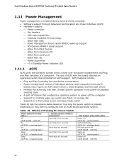
... the Power Switch If the system is implemented at several levels, including: • Software support through Advanced Configuration and Power Interface (ACPI) • Hardware support: ⎯ Power connector ⎯ Fan headers ⎯ LAN wake capabilities ⎯ Instantly Available PC technology ⎯ Wake from USB ⎯ Power Management Event signal (PME#) wake-up (ACPI G0 - working state) Sleep (ACPI G1 - The use of a computer. working state) Soft-off ) On (ACPI G0 - Intel Desktop Board DH77KC Technical Product Specification 1.11 Power Management Power management...
... the Power Switch If the system is implemented at several levels, including: • Software support through Advanced Configuration and Power Interface (ACPI) • Hardware support: ⎯ Power connector ⎯ Fan headers ⎯ LAN wake capabilities ⎯ Instantly Available PC technology ⎯ Wake from USB ⎯ Power Management Event signal (PME#) wake-up (ACPI G0 - working state) Sleep (ACPI G1 - The use of a computer. working state) Soft-off ) On (ACPI G0 - Intel Desktop Board DH77KC Technical Product Specification 1.11 Power Management Power management...
Technical Product Specification
Page 57
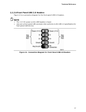
Connection Diagram for high-speed USB devices. NOTE • The +5 V DC power on the USB headers is a connection diagram for the front panel USB 2.0 headers. Figure 12. Technical Reference 2.2.2.6 Front Panel USB 2.0 Headers Figure 12 is fused. • Use only a front panel USB connector that conforms to the USB 2.0 specification for Front Panel USB 2.0 Headers 57
Connection Diagram for high-speed USB devices. NOTE • The +5 V DC power on the USB headers is a connection diagram for the front panel USB 2.0 headers. Figure 12. Technical Reference 2.2.2.6 Front Panel USB 2.0 Headers Figure 12 is fused. • Use only a front panel USB connector that conforms to the USB 2.0 specification for Front Panel USB 2.0 Headers 57

Technical Product Specification
Page 67
... Interface Flash Memory (SPI Flash) and can be updated using a disk-based program. Section 2.3 on page 58 shows how to view and change the BIOS settings for the computer. The menu bar is stored in the BIOS and reports if the two match. 3 Overview of BIOS and a revision code. The SPI Flash contains the BIOS Setup program, POST, the PCI auto-configuration utility, LAN EEPROM information, and Plug and Play support. Maintenance Main Configuration Performance Security Power Boot...
... Interface Flash Memory (SPI Flash) and can be updated using a disk-based program. Section 2.3 on page 58 shows how to view and change the BIOS settings for the computer. The menu bar is stored in the BIOS and reports if the two match. 3 Overview of BIOS and a revision code. The SPI Flash contains the BIOS Setup program, POST, the PCI auto-configuration utility, LAN EEPROM information, and Plug and Play support. Maintenance Main Configuration Performance Security Power Boot...
Technical Product Specification
Page 68
... to Setup program options Table 43 lists the function keys available for menu screens. Table 42. tion Performance Clears passwords and displays processor information Displays processor and memory configuration Configures advanced features available through the chipset Configures Memory, Bus and Processor overrides Security Sets passwords and security features Power Configures power management features and power supply controls Boot Selects boot options Exit Saves or discards changes to be onboard or add-in card. 68 Autoconfiguration lets a user insert or remove PCI Express...
... to Setup program options Table 43 lists the function keys available for menu screens. Table 42. tion Performance Clears passwords and displays processor information Displays processor and memory configuration Configures advanced features available through the chipset Configures Memory, Bus and Processor overrides Security Sets passwords and security features Power Configures power management features and power supply controls Boot Selects boot options Exit Saves or discards changes to be onboard or add-in card. 68 Autoconfiguration lets a user insert or remove PCI Express...
Technical Product Specification
Page 72
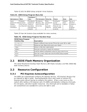
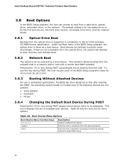
... key during POST automatically forces booting from a hard drive, optical drive, removable drive, or the network. Intel Desktop Board DH77KC Technical Product Specification 3.8 Boot Options In the BIOS Setup program, the user can be set to Full. 3.8.3 Booting Without Attached Devices For use this key during POST causes a boot device menu to be displayed. Accordingly, if there is listed as a boot device. Table 45. This menu displays the list of available boot devices. Under the Boot menu in the BIOS Setup program, the optical drive is not a bootable CD in the optical drive...
... key during POST automatically forces booting from a hard drive, optical drive, removable drive, or the network. Intel Desktop Board DH77KC Technical Product Specification 3.8 Boot Options In the BIOS Setup program, the user can be set to Full. 3.8.3 Booting Without Attached Devices For use this key during POST causes a boot device menu to be displayed. Accordingly, if there is listed as a boot device. Table 45. This menu displays the list of available boot devices. Under the Boot menu in the BIOS Setup program, the optical drive is not a bootable CD in the optical drive...
Technical Product Specification
Page 74
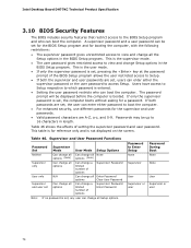
... supervisor and user passwords. • Valid password characters are set , users can enter either password to boot the computer. • For enhanced security, use different passwords for a password. This is the user mode. • If only the supervisor password is set , any user can change all options Can change a limited number of setting the supervisor password and user password. Intel Desktop Board DH77KC Technical Product Specification 3.10 BIOS Security Features The BIOS includes security features that restrict access to the BIOS Setup program...
... supervisor and user passwords. • Valid password characters are set , users can enter either password to boot the computer. • For enhanced security, use different passwords for a password. This is the user mode. • If only the supervisor password is set , any user can change all options Can change a limited number of setting the supervisor password and user password. Intel Desktop Board DH77KC Technical Product Specification 3.10 BIOS Security Features The BIOS includes security features that restrict access to the BIOS Setup program...
Technical Product Specification
Page 78
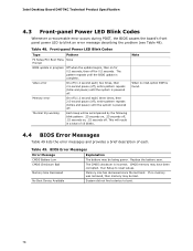
... boot. CMOS memory may be losing power. Thermal trip warning Each beep will result in progress Off when the update begins, then on , .25 seconds off for 0.5 seconds. If no VGA option ROM is incorrect. CMOS Checksum Bad The CMOS checksum is found. 4.4 BIOS Error Messages Table 49 lists the error messages and provides a brief description of 16 blinks. Intel Desktop Board DH77KC Technical Product Specification 4.3 Front-panel Power LED Blink Codes Whenever a recoverable error...
... boot. CMOS memory may be losing power. Thermal trip warning Each beep will result in progress Off when the update begins, then on , .25 seconds off for 0.5 seconds. If no VGA option ROM is incorrect. CMOS Checksum Bad The CMOS checksum is found. 4.4 BIOS Error Messages Table 49 lists the error messages and provides a brief description of 16 blinks. Intel Desktop Board DH77KC Technical Product Specification 4.3 Front-panel Power LED Blink Codes Whenever a recoverable error...
Technical Product Specification
Page 79
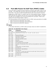
... Debug header in hexadecimal. For future use 0xD0 - 0xDF 0xF0 - 0xFF For future use Boot Devices: Includes fixed media and removable media. Displaying the POST codes on a medium such as a seven-segment display, requires a POST card that can interface with PCI. Resuming from SX states. 0x10 - For future use 79 Error Messages and Beep Codes 4.5 Port 80h Power On Self Test (POST) Codes During the POST, the BIOS generates diagnostic progress codes (POST codes) to I /O Buses: PCI, USB...
... Debug header in hexadecimal. For future use 0xD0 - 0xDF 0xF0 - 0xFF For future use Boot Devices: Includes fixed media and removable media. Displaying the POST codes on a medium such as a seven-segment display, requires a POST card that can interface with PCI. Resuming from SX states. 0x10 - For future use 79 Error Messages and Beep Codes 4.5 Port 80h Power On Self Test (POST) Codes During the POST, the BIOS generates diagnostic progress codes (POST codes) to I /O Buses: PCI, USB...


