
DG965MQ Technical Product Specification
Page 5
... Manufacturing Options 11 1.1.3 Board Layout 12 1.1.4 Block Diagram 14 1.2 Online Support 15 1.3 Processor 15 1.4 System Memory 16 1.4.1 Memory Configurations 18 1.5 Intel® G965 Express Chipset 23 1.5.1 Intel G965 Graphics Subsystem 23 1.5.2 USB 26 1.5.3 Serial ATA Interfaces 27 1.5.4 Parallel IDE Interface ... 29 1.7 Audio Subsystem 30 1.7.1 Audio Subsystem Software 30 1.7.2 Audio Connectors and Headers 31 1.8 LAN Subsystem 32 1.8.1 Intel® 82566DC Gigabit Ethernet Controller 32 1.8.2 LAN Subsystem Software 33 1.8.3 RJ-45 LAN Connector with Integrated LEDs 33 1.9...
... Manufacturing Options 11 1.1.3 Board Layout 12 1.1.4 Block Diagram 14 1.2 Online Support 15 1.3 Processor 15 1.4 System Memory 16 1.4.1 Memory Configurations 18 1.5 Intel® G965 Express Chipset 23 1.5.1 Intel G965 Graphics Subsystem 23 1.5.2 USB 26 1.5.3 Serial ATA Interfaces 27 1.5.4 Parallel IDE Interface ... 29 1.7 Audio Subsystem 30 1.7.1 Audio Subsystem Software 30 1.7.2 Audio Connectors and Headers 31 1.8 LAN Subsystem 32 1.8.1 Intel® 82566DC Gigabit Ethernet Controller 32 1.8.2 LAN Subsystem Software 33 1.8.3 RJ-45 LAN Connector with Integrated LEDs 33 1.9...

DG965MQ Technical Product Specification
Page 8
...Error Messages 79 45. Main Power Connector 57 29. BIOS Setup Program Menu Bar 72 39. Boot Device Menu Options 76 42. Intel Desktop Board DG965MQ Technical Product Specification 10. System Memory Map 45 13. PCI Configuration Space Map 47 16. Serial Port Header 54 23. Safety Regulations... Markings 93 viii Component-side Connectors and Headers Shown in Figure 16 53 19. Processor Fan Header 55 26. Typical Port 80h POST Sequence 84 48. Front Panel Audio Header 55 27. Processor Core Power Connector 57 28. Acceptable Drives/Media Types for a Two-Color Power LED...
...Error Messages 79 45. Main Power Connector 57 29. BIOS Setup Program Menu Bar 72 39. Boot Device Menu Options 76 42. Intel Desktop Board DG965MQ Technical Product Specification 10. System Memory Map 45 13. PCI Configuration Space Map 47 16. Serial Port Header 54 23. Safety Regulations... Markings 93 viii Component-side Connectors and Headers Shown in Figure 16 53 19. Processor Fan Header 55 26. Typical Port 80h POST Sequence 84 48. Front Panel Audio Header 55 27. Processor Core Power Connector 57 28. Acceptable Drives/Media Types for a Two-Color Power LED...
DG965MQ Technical Product Specification
Page 9
1 Product Description What This Chapter Contains 1.1 Overview 10 1.2 Online Support 15 1.3 Processor 15 1.4 System Memory 16 1.5 Intel® G965 Express Chipset 23 1.6 Legacy I/O Controller 29 1.7 Audio Subsystem 30 1.8 LAN Subsystem 32 1.9 Hardware Management Subsystem 34 1.10 Power Management 36 9
1 Product Description What This Chapter Contains 1.1 Overview 10 1.2 Online Support 15 1.3 Processor 15 1.4 System Memory 16 1.5 Intel® G965 Express Chipset 23 1.6 Legacy I/O Controller 29 1.7 Audio Subsystem 30 1.8 LAN Subsystem 32 1.9 Hardware Management Subsystem 34 1.10 Power Management 36 9
DG965MQ Technical Product Specification
Page 10
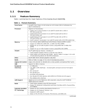
...Intel® Core™2 Duo processor in an LGA775 socket with a 1066 or 800 MHz system bus • Intel® Pentium® D processor...Intel® Pentium® 4 processor in an LGA775 socket with an 800 or 533 MHz system bus • Intel® Celeron® D processor...Intel® GMA X3000 onboard graphics subsystem Refer to Table 2 on page 11 for a list of : • Intel® 82G965 Graphics Memory Controller Hub (GMCH) • Intel... the Intel® 82566DC Gigabit Ethernet Controller • Intel®...LAN subsystem using DDR2 800 DIMMs Intel® G965 Express Chipset, consisting...
...Intel® Core™2 Duo processor in an LGA775 socket with a 1066 or 800 MHz system bus • Intel® Pentium® D processor...Intel® Pentium® 4 processor in an LGA775 socket with an 800 or 533 MHz system bus • Intel® Celeron® D processor...Intel® GMA X3000 onboard graphics subsystem Refer to Table 2 on page 11 for a list of : • Intel® 82G965 Graphics Memory Controller Hub (GMCH) • Intel... the Intel® 82566DC Gigabit Ethernet Controller • Intel®...LAN subsystem using DDR2 800 DIMMs Intel® G965 Express Chipset, consisting...
DG965MQ Technical Product Specification
Page 13
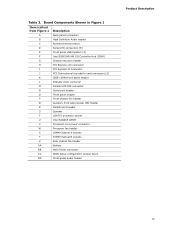
... Back panel connectors B High Definition Audio header C Remote thermal sensor D Serial ATA connectors [6] E Front panel USB headers [2] F Intel 82801HR/HH I/O Controller Hub (ICH8) G Chassis intrusion header H PCI Express x16 connector I PCI Express x1 connector J PCI Conventional ... chassis fan header Q Auxiliary front panel power LED header R Parallel port header S Speaker T LGA775 processor socket U Intel 82G965 GMCH V Processor core power connector W Processor fan header X DIMM Channel A sockets Y DIMM Channel B sockets Z Rear chassis fan header AA ...
... Back panel connectors B High Definition Audio header C Remote thermal sensor D Serial ATA connectors [6] E Front panel USB headers [2] F Intel 82801HR/HH I/O Controller Hub (ICH8) G Chassis intrusion header H PCI Express x16 connector I PCI Express x1 connector J PCI Conventional ... chassis fan header Q Auxiliary front panel power LED header R Parallel port header S Speaker T LGA775 processor socket U Intel 82G965 GMCH V Processor core power connector W Processor fan header X DIMM Channel A sockets Y DIMM Channel B sockets Z Rear chassis fan header AA ...
DG965MQ Technical Product Specification
Page 15
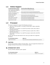
... to Section 2.7.2.2, page 57 15 Product Description 1.2 Online Support To find information about ... For information about ... Intel® Desktop Board DG965MQ under "Desktop Board Products" or "Desktop Board Support" Available configurations for the Desktop Board DG965MQ Processor data sheets ICH8 addressing Audio software and utilities LAN software and drivers Supported video modes Visit this...
... to Section 2.7.2.2, page 57 15 Product Description 1.2 Online Support To find information about ... For information about ... Intel® Desktop Board DG965MQ under "Desktop Board Products" or "Desktop Board Support" Available configurations for the Desktop Board DG965MQ Processor data sheets ICH8 addressing Audio software and utilities LAN software and drivers Supported video modes Visit this...

DG965MQ Technical Product Specification
Page 17
Table 5. Memory Operating Frequencies DIMM Type Processor system bus frequency DDR2 533 533 MHz DDR2 533 800 MHz DDR2 533 1066 MHz DDR2 667 533 MHz DDR2 667 800 MHz DDR2 667 ... the resulting operating memory frequencies based on the combination of the DIMM type used with a 533 MHz system bus frequency processor, the memory will either be equal to or less than the processor system bus frequency. For example, if DDR2 800 memory is used , the memory frequency will operate at 533 MHz...
Table 5. Memory Operating Frequencies DIMM Type Processor system bus frequency DDR2 533 533 MHz DDR2 533 800 MHz DDR2 533 1066 MHz DDR2 667 533 MHz DDR2 667 800 MHz DDR2 667 ... the resulting operating memory frequencies based on the combination of the DIMM type used with a 533 MHz system bus frequency processor, the memory will either be equal to or less than the processor system bus frequency. For example, if DDR2 800 memory is used , the memory frequency will operate at 533 MHz...
DG965MQ Technical Product Specification
Page 28
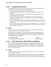
...and require a specialized cable to the BIOS. The Parallel ATA IDE interface supports the following modes: • Programmed I/O (PIO): processor controls data transfer. • 8237-style DMA: DMA offloads the processor, supporting transfer rates of up to 16 MB/sec. • Ultra DMA: DMA protocol on IDE bus supporting host and...) might not be loaded into a wall socket, the battery has an estimated life of the Parallel ATA IDE connector Refer to 66 MB/sec. Intel Desktop Board DG965MQ Technical Product Specification 1.5.4 Parallel IDE Interface The Parallel ATA IDE controller has one .
...and require a specialized cable to the BIOS. The Parallel ATA IDE interface supports the following modes: • Programmed I/O (PIO): processor controls data transfer. • 8237-style DMA: DMA offloads the processor, supporting transfer rates of up to 16 MB/sec. • Ultra DMA: DMA protocol on IDE bus supporting host and...) might not be loaded into a wall socket, the battery has an estimated life of the Parallel ATA IDE connector Refer to 66 MB/sec. Intel Desktop Board DG965MQ Technical Product Specification 1.5.4 Parallel IDE Interface The Parallel ATA IDE controller has one .

DG965MQ Technical Product Specification
Page 34
...Intel Desktop Board DG965MQ Technical Product Specification 1.9 Hardware Management Subsystem The hardware management features enable the board to the chassis intrusion header. When the chassis cover is removed, the mechanical switch is removed. The security feature uses a mechanical switch on or off as needed 1.9.2 Fan Monitoring Fan monitoring can be implemented using Intel...• Intel Quiet System Technology, delivering acoustically-optimized thermal management • Fan speed control controllers and sensors integrated into the ICH8 • Four thermal sensors (processor, 82G965 ...
...Intel Desktop Board DG965MQ Technical Product Specification 1.9 Hardware Management Subsystem The hardware management features enable the board to the chassis intrusion header. When the chassis cover is removed, the mechanical switch is removed. The security feature uses a mechanical switch on or off as needed 1.9.2 Fan Monitoring Fan monitoring can be implemented using Intel...• Intel Quiet System Technology, delivering acoustically-optimized thermal management • Fan speed control controllers and sensors integrated into the ICH8 • Four thermal sensors (processor, 82G965 ...

DG965MQ Technical Product Specification
Page 35
Thermal Sensors and Fan Headers 35 Product Description 1.9.4 Thermal Monitoring Figure 12 shows the locations of the thermal sensors and fan headers. C G D E B A F Item A B C D E F G Description Thermal diode, located on processor die Thermal diode, located on the GMCH die Thermal diode, located on the ICH8 die Remote thermal sensor Processor fan Front chassis fan Rear chassis fan OM18420 Figure 12.
Thermal Sensors and Fan Headers 35 Product Description 1.9.4 Thermal Monitoring Figure 12 shows the locations of the thermal sensors and fan headers. C G D E B A F Item A B C D E F G Description Thermal diode, located on processor die Thermal diode, located on the GMCH die Thermal diode, located on the ICH8 die Remote thermal sensor Processor fan Front chassis fan Rear chassis fan OM18420 Figure 12.
DG965MQ Technical Product Specification
Page 37
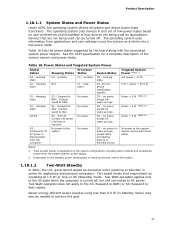
... add-in S5 (Standby) mode. Context saved to the S5 state when the computer is required. Notes: 1. Power States and Targeted System Power Global States Processor Sleeping States States Device States Targeted System Power (Note 1) G0 - Table 10 lists the power states supported by the system chassis' power supply. 2. The operating...
... add-in S5 (Standby) mode. Context saved to the S5 state when the computer is required. Notes: 1. Power States and Targeted System Power Global States Processor Sleeping States States Device States Targeted System Power (Note 1) G0 - Table 10 lists the power states supported by the system chassis' power supply. 2. The operating...

DG965MQ Technical Product Specification
Page 39
... or off the system power through system control. For information about The locations of the fan headers and thermal sensors The signal names of the processor fan header The signal names of the hardware monitoring and fan control device. • All fan headers support closed-loop fan control that can turn...
... or off the system power through system control. For information about The locations of the fan headers and thermal sensors The signal names of the processor fan header The signal names of the hardware monitoring and fan control device. • All fan headers support closed-loop fan control that can turn...

DG965MQ Technical Product Specification
Page 53
... K Parallel ATA IDE connector L Serial port header M Front panel header N Front chassis fan header O Auxiliary front panel power LED header P Parallel port header Q Processor core power connector R Processor fan connector S Rear chassis fan header T Main power connector U Front panel audio header 53 Table 18. Component-side Connectors and Headers Shown in Figure...
... K Parallel ATA IDE connector L Serial port header M Front panel header N Front chassis fan header O Auxiliary front panel power LED header P Parallel port header Q Processor core power connector R Processor fan connector S Rear chassis fan header T Main power connector U Front panel audio header 53 Table 18. Component-side Connectors and Headers Shown in Figure...

DG965MQ Technical Product Specification
Page 55
... 1] Right channel 4 5 [Port 2] Right channel 6 7 SENSE_SEND (Jack detection) 8 9 [Port 2] Left channel 10 Signal Name Ground PRESENCE# (Dongle present) [Port 1] SENSE_RETURN Key (no pin) Table 24. Processor Fan Header Pin Signal Name 1 Ground 2 +12 V 3 FAN_TACH 4 FAN_CONTROL Table 26. Technical Reference Table 23.
... 1] Right channel 4 5 [Port 2] Right channel 6 7 SENSE_SEND (Jack detection) 8 9 [Port 2] Left channel 10 Signal Name Ground PRESENCE# (Dongle present) [Port 1] SENSE_RETURN Key (no pin) Table 24. Processor Fan Header Pin Signal Name 1 Ground 2 +12 V 3 FAN_TACH 4 FAN_CONTROL Table 26. Technical Reference Table 23.
DG965MQ Technical Product Specification
Page 57
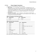
... power directly to do so will be used on the rightmost pins of ATX12V power supplies with a 2 x 10 main power cable, attach that cable on Intel Desktop boards. Main Power Connector Pin Signal Name Pin Signal Name 1 +3.3 V 13 +3.3 V 2 +3.3 V 14 -12 V 3 Ground 15 Ground 4 +5 V 16 PS-ON# (power supply ... or 2 x 12 main power cables. The board supports the use of the main power connector, leaving pins 11, 12, 23, and 24 unconnected. • Processor core power - When using a 2 x 10 power supply cable, this pin will prevent the board from booting. Failure to the...
... power directly to do so will be used on the rightmost pins of ATX12V power supplies with a 2 x 10 main power cable, attach that cable on Intel Desktop boards. Main Power Connector Pin Signal Name Pin Signal Name 1 +3.3 V 13 +3.3 V 2 +3.3 V 14 -12 V 3 Ground 15 Ground 4 +5 V 16 PS-ON# (power supply ... or 2 x 12 main power cables. The board supports the use of the main power connector, leaving pins 11, 12, 23, and 24 unconnected. • Processor core power - When using a 2 x 10 power supply cable, this pin will prevent the board from booting. Failure to the...

DG965MQ Technical Product Specification
Page 61
... recovery. See Section 3.7 for more information on . The jumper determines the BIOS Setup program's mode. The maintenance menu is powered-up, the BIOS compares the processor version and the microcode version in the BIOS and reports if the two match. 1 2 3 Figure 20. Recovery None 123 123 The BIOS attempts to configure...
... recovery. See Section 3.7 for more information on . The jumper determines the BIOS Setup program's mode. The maintenance menu is powered-up, the BIOS compares the processor version and the microcode version in the BIOS and reports if the two match. 1 2 3 Figure 20. Recovery None 123 123 The BIOS attempts to configure...

DG965MQ Technical Product Specification
Page 65
... requirements. The selection of all active components within the board that will halt fan operation. Fan Header Current Capability Fan Header Maximum Available Current Processor fan Front chassis fan Rear chassis fan 3.0 A 1.5 A 1.5 A 65 This data is dependent on the board that is similar to ...a heavy gaming environment with no applications running and no USB current draw. Table 35. Connecting the processor fan to a chassis fan header may result in onboard component damage that impact its power delivery subsystems. The analysis does not ...
... requirements. The selection of all active components within the board that will halt fan operation. Fan Header Current Capability Fan Header Maximum Available Current Processor fan Front chassis fan Rear chassis fan 3.0 A 1.5 A 1.5 A 65 This data is dependent on the board that is similar to ...a heavy gaming environment with no applications running and no USB current draw. Table 35. Connecting the processor fan to a chassis fan header may result in onboard component damage that impact its power delivery subsystems. The analysis does not ...

DG965MQ Technical Product Specification
Page 67
... Failure to ensure appropriate airflow may result in the processor voltage regulator circuit. For a list of chassis that merely following website: http://developer.intel.com/design/motherbd/cooling.htm All responsibility for the processor. Technical Reference 2.11 Thermal Considerations CAUTION This board ... 24) can reach a temperature of up to the board. The processor voltage regulator area (shown in Section 2.13. Intel makes no warranties or representations that have been tested with Intel desktop boards please refer to exceed their maximum case temperature and malfunction....
... Failure to ensure appropriate airflow may result in the processor voltage regulator circuit. For a list of chassis that merely following website: http://developer.intel.com/design/motherbd/cooling.htm All responsibility for the processor. Technical Reference 2.11 Thermal Considerations CAUTION This board ... 24) can reach a temperature of up to the board. The processor voltage regulator area (shown in Section 2.13. Intel makes no warranties or representations that have been tested with Intel desktop boards please refer to exceed their maximum case temperature and malfunction....

DG965MQ Technical Product Specification
Page 68
Intel Desktop Board DG965MQ Technical Product Specification Figure 24 shows the locations of the localized high temperature zones. A BC E D Item A B C D E OM18426 Description Intel 82G965 GMCH Intel 82801HR/HH ICH8 1.5 V core and front side bus voltage regulator areas Processor Processor voltage regulator area Figure 24. Localized High Temperature Zones 68
Intel Desktop Board DG965MQ Technical Product Specification Figure 24 shows the locations of the localized high temperature zones. A BC E D Item A B C D E OM18426 Description Intel 82G965 GMCH Intel 82801HR/HH ICH8 1.5 V core and front side bus voltage regulator areas Processor Processor voltage regulator area Figure 24. Localized High Temperature Zones 68

DG965MQ Technical Product Specification
Page 69
...load, or operating frequency could affect case temperatures. The MTBF data is 105,367 hours. 69 The Desktop Board DG965MQ MTBF is calculated from predicted data at 55 ºC. Thermal Considerations for the board components that are important when considering...board. Technical Reference Table 36 provides maximum case temperatures for Components Component Maximum Case Temperature Processor For processor case temperature, see processor datasheets and processor specification updates Intel 82G965 GMCH Intel 82801HR/HH ICH8R/ICH8DH 97 oC (under bias) 105 oC (under bias) For...
...load, or operating frequency could affect case temperatures. The MTBF data is 105,367 hours. 69 The Desktop Board DG965MQ MTBF is calculated from predicted data at 55 ºC. Thermal Considerations for the board components that are important when considering...board. Technical Reference Table 36 provides maximum case temperatures for Components Component Maximum Case Temperature Processor For processor case temperature, see processor datasheets and processor specification updates Intel 82G965 GMCH Intel 82801HR/HH ICH8R/ICH8DH 97 oC (under bias) 105 oC (under bias) For...


