Product Guide
Page 6
Intel Desktop Board DG33BU Product Guide Installing and Removing a Processor 29 Installing a Processor 29 Installing the Processor Fan Heat Sink 32 Connecting the Processor Fan Heat Sink Cable 33 ... 42 Connecting the Serial ATA (SATA) Cables 44 Connecting to the Internal Headers 45 Connecting to the IEEE 1394a Header 46 Installing a Front Panel Audio Solution for Intel® High Definition Audio 46 Connecting to the Serial Port Header 47 Connecting to the Chassis Intrusion Header 47 Connecting to the Alternate Front...
Intel Desktop Board DG33BU Product Guide Installing and Removing a Processor 29 Installing a Processor 29 Installing the Processor Fan Heat Sink 32 Connecting the Processor Fan Heat Sink Cable 33 ... 42 Connecting the Serial ATA (SATA) Cables 44 Connecting to the Internal Headers 45 Connecting to the IEEE 1394a Header 46 Installing a Front Panel Audio Solution for Intel® High Definition Audio 46 Connecting to the Serial Port Header 47 Connecting to the Chassis Intrusion Header 47 Connecting to the Alternate Front...
Product Guide
Page 7
...33 13. Dual Channel Memory Configuration with Two DIMMs 34 14. Use DDR2 DIMMs 36 17. Internal Headers 45 24. Removing the Battery 58 vii Desktop Board DG33BU Mounting Screw Hole Locations 28 6. Lift the Load Plate 30 8. Dual Channel Memory Configuration with Three DIMMs 35 16. Removing a PCI Express x16 Card... the Load Plate 32 12. Installing a DIMM 37 18. Installing a PCI Express x16 Card 39 19. Connecting the Diskette Drive Cable 41 21. Back Panel Audio Connectors 49 25. Location of the Standby Power Indicator 22 4. Connecting Power Supply Cables 51 27.
...33 13. Dual Channel Memory Configuration with Two DIMMs 34 14. Use DDR2 DIMMs 36 17. Internal Headers 45 24. Removing the Battery 58 vii Desktop Board DG33BU Mounting Screw Hole Locations 28 6. Lift the Load Plate 30 8. Dual Channel Memory Configuration with Three DIMMs 35 16. Removing a PCI Express x16 Card... the Load Plate 32 12. Installing a DIMM 37 18. Installing a PCI Express x16 Card 39 19. Connecting the Diskette Drive Cable 41 21. Back Panel Audio Connectors 49 25. Location of the Standby Power Indicator 22 4. Connecting Power Supply Cables 51 27.
Product Guide
Page 8
LAN Connector LEDs 17 4. Alternate Front Panel Power LED Header 47 9. Jumper Settings for Intel High Definition Audio 46 6. Safety Regulations 65 15. Desktop Board DG33BU Components 12 3. BIOS Error Messages 63 14. Intel Desktop Board DG33BU Product Guide Tables 1. USB 2.0 Header Signal Names 48 11. Lead-Free Board Markings 71 16. Product Certification Markings 74 viii Serial Port Header Signal...
LAN Connector LEDs 17 4. Alternate Front Panel Power LED Header 47 9. Jumper Settings for Intel High Definition Audio 46 6. Safety Regulations 65 15. Desktop Board DG33BU Components 12 3. BIOS Error Messages 63 14. Intel Desktop Board DG33BU Product Guide Tables 1. USB 2.0 Header Signal Names 48 11. Lead-Free Board Markings 71 16. Product Certification Markings 74 viii Serial Port Header Signal...
Product Guide
Page 9
...; Up to two IEEE 1394a ports ― One port routed to the back panel ― One port routed to 8 GB of system memory Intel® G33 Express Chipset consisting of Intel® Desktop Board DG33BU. Feature Summary Form Factor Processor microATX (243.84 millimeters [9.60 inches] x 243....84 millimeters [9.60 inches]) Support for an Intel® processor in the LGA775 package Main Memory...
...; Up to two IEEE 1394a ports ― One port routed to the back panel ― One port routed to 8 GB of system memory Intel® G33 Express Chipset consisting of Intel® Desktop Board DG33BU. Feature Summary Form Factor Processor microATX (243.84 millimeters [9.60 inches] x 243....84 millimeters [9.60 inches]) Support for an Intel® processor in the LGA775 package Main Memory...
Product Guide
Page 10
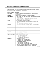
...on USB, PCI Express, PS/2, LAN, and front panel • ENGERY STAR* qualified desktop board Hardware Management Hardware monitor with: • Three fan sensing inputs used to monitor fan activity • Intel® Quiet System Technology fan speed control •...LAN controller Related Links: For more information about Desktop Board DG33BU, including the Technical Product Specification (TPS), BIOS updates, and device drivers, go to: http://support.intel.com/support/motherboards/desktop/ Supported Operating Systems The Desktop Board supports the following operating systems: • ...
...on USB, PCI Express, PS/2, LAN, and front panel • ENGERY STAR* qualified desktop board Hardware Management Hardware monitor with: • Three fan sensing inputs used to monitor fan activity • Intel® Quiet System Technology fan speed control •...LAN controller Related Links: For more information about Desktop Board DG33BU, including the Technical Product Specification (TPS), BIOS updates, and device drivers, go to: http://support.intel.com/support/motherboards/desktop/ Supported Operating Systems The Desktop Board supports the following operating systems: • ...
Product Guide
Page 12
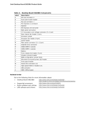
... BIOS configuration jumper block Alternate front panel power LED header Front panel header Serial ATA connectors (4) High-speed USB 2.0 headers (3) IDE connector IEEE 1394a header Related Links: Go to the following links for more information about: • Desktop Board DG33BU http://www.intel.com/design/motherbd http://support.intel.com/support/motherboards/desktop • Supported processors • Audio software...
... BIOS configuration jumper block Alternate front panel power LED header Front panel header Serial ATA connectors (4) High-speed USB 2.0 headers (3) IDE connector IEEE 1394a header Related Links: Go to the following links for more information about: • Desktop Board DG33BU http://www.intel.com/design/motherbd http://support.intel.com/support/motherboards/desktop • Supported processors • Audio software...
Product Guide
Page 15
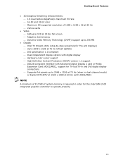
Desktop Board Features • 3D Graphics Rendering enhancements: ⎯ 1.6 dual texture GigaPixel/s maximum fill rate ⎯ ...fps full screen ⎯ Adaptive deinterlacing ⎯ Dynamic Video Memory Technology (DVMT) support up to 256 MB • Display ⎯ Intel TV Wizard utility (step-by-step setup help for TVs and displays) ⎯ Up to 2048 x 1536 at 75 Hz refresh ... or Media Expansion Card (ADD2/MEC), support for TV-out/TV-in and DVI digital display connections ⎯ Supports flat panels up to 2048 x 1536 at 75 Hz (when in dual-channel mode) or digital CRT/HDTV at 1920 x 1080 ...
Desktop Board Features • 3D Graphics Rendering enhancements: ⎯ 1.6 dual texture GigaPixel/s maximum fill rate ⎯ ...fps full screen ⎯ Adaptive deinterlacing ⎯ Dynamic Video Memory Technology (DVMT) support up to 256 MB • Display ⎯ Intel TV Wizard utility (step-by-step setup help for TVs and displays) ⎯ Up to 2048 x 1536 at 75 Hz refresh ... or Media Expansion Card (ADD2/MEC), support for TV-out/TV-in and DVI digital display connections ⎯ Supports flat panels up to 2048 x 1536 at 75 Hz (when in dual-channel mode) or digital CRT/HDTV at 1920 x 1080 ...
Product Guide
Page 16
Intel Desktop Board DG33BU Product Guide Audio Subsystem The onboard audio subsystem consists of the following: • Intel ICH9DH I /O controller features the following: • Low pin count (LPC) interface • One serial port interface via an onboard header...; Serial IRQ interface compatible with serialized IRQ support for more information about: • Audio drivers and utilities http://support.intel.com/support/motherboards/desktop/ • Installing the front panel audio solution, page 46 • The location of 95 dB • Independent multi-streaming 5.1 audio (using the back...
Intel Desktop Board DG33BU Product Guide Audio Subsystem The onboard audio subsystem consists of the following: • Intel ICH9DH I /O controller features the following: • Low pin count (LPC) interface • One serial port interface via an onboard header...; Serial IRQ interface compatible with serialized IRQ support for more information about: • Audio drivers and utilities http://support.intel.com/support/motherboards/desktop/ • Installing the front panel audio solution, page 46 • The location of 95 dB • Independent multi-streaming 5.1 audio (using the back...
Product Guide
Page 17
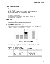
Figure 2. LAN Connector LEDs Table 3 describes the LED states when the board is powered up and the LAN subsystem is occurring 10 Mb/s data... LAN activity is operating. These LEDs indicate the status of the LAN. Desktop Board Features LAN Subsystem The LAN subsystem includes: • Intel® ICH9DH • Intel 82566DC Gigabit (10/100/1000 Mb/s) Ethernet LAN controller • RJ-...to the following link for information about LAN software and drivers: http://support.intel.com/support/motherboards/desktop RJ-45 LAN Connector LEDs Two LEDs are built into the RJ-45 LAN connector located on ...
Figure 2. LAN Connector LEDs Table 3 describes the LED states when the board is powered up and the LAN subsystem is occurring 10 Mb/s data... LAN activity is operating. These LEDs indicate the status of the LAN. Desktop Board Features LAN Subsystem The LAN subsystem includes: • Intel® ICH9DH • Intel 82566DC Gigabit (10/100/1000 Mb/s) Ethernet LAN controller • RJ-...to the following link for information about LAN software and drivers: http://support.intel.com/support/motherboards/desktop RJ-45 LAN Connector LEDs Two LEDs are built into the RJ-45 LAN connector located on ...
Product Guide
Page 18
...Ultra DMA-33 and ATA-66/100 protocols Serial ATA The Desktop Board supports four Serial ATA channels (3.0 Gb/s) via the ICH9DH. Intel Desktop Board DG33BU Product Guide Hi-Speed USB 2.0 Support The Desktop Board supports up to 12 USB 2.0 ports (six ports routed to the back panel and six ports routed to USB 1.1 operation. USB 2.0... and IDE auto-configuration utilities, and the video BIOS. The BIOS is stored in Chapter 3. 18 Expandability For system expansion, the Desktop Board provides the following the instructions on page 59 in the Serial Peripheral Interface (SPI) Flash device.
...Ultra DMA-33 and ATA-66/100 protocols Serial ATA The Desktop Board supports four Serial ATA channels (3.0 Gb/s) via the ICH9DH. Intel Desktop Board DG33BU Product Guide Hi-Speed USB 2.0 Support The Desktop Board supports up to 12 USB 2.0 ports (six ports routed to the back panel and six ports routed to USB 1.1 operation. USB 2.0... and IDE auto-configuration utilities, and the video BIOS. The BIOS is stored in Chapter 3. 18 Expandability For system expansion, the Desktop Board provides the following the instructions on page 59 in the Serial Peripheral Interface (SPI) Flash device.
Product Guide
Page 22
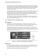
... installing or removing any attached devices. Figure 3. Location of the Standby Power Indicator Related Links: For more information on the front panel, the sleep state is still present at the memory module sockets and the PCI bus connectors. If the standby current necessary to....intel.com/support/motherboards/desktop/ 22 For example, when this Desktop Board must be able to provide enough standby current to be used with this LED is lit, standby power is indicated by a wake-up device or event, the computer quickly returns to its last known awake state. Intel Desktop Board DG33BU ...
... installing or removing any attached devices. Figure 3. Location of the Standby Power Indicator Related Links: For more information on the front panel, the sleep state is still present at the memory module sockets and the PCI bus connectors. If the standby current necessary to....intel.com/support/motherboards/desktop/ 22 For example, when this Desktop Board must be able to provide enough standby current to be used with this LED is lit, standby power is indicated by a wake-up device or event, the computer quickly returns to its last known awake state. Intel Desktop Board DG33BU ...
Product Guide
Page 25
... in this chapter only at an ESD workstation using and modifying electronic equipment. Some circuitry on the board can continue to operate even though the front panel power button is not available, you can damage components. Disconnect the computer from its power source and... it to a metal part of the procedures described in this chapter. 2 Installing and Replacing Desktop Board Components This chapter tells you how to: • Install the I/O shield • Install and remove the Desktop Board • Install and remove a processor • Install and remove memory • Install and...
... in this chapter only at an ESD workstation using and modifying electronic equipment. Some circuitry on the board can continue to operate even though the front panel power button is not available, you can damage components. Disconnect the computer from its power source and... it to a metal part of the procedures described in this chapter. 2 Installing and Replacing Desktop Board Components This chapter tells you how to: • Install the I/O shield • Install and remove the Desktop Board • Install and remove a processor • Install and remove memory • Install and...
Product Guide
Page 39
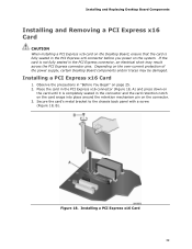
... bracket to the chassis back panel with a screw (Figure 18, B). If the card is not fully seated in the PCI Express connector, an electrical short may be damaged. Depending on the over-current protection of the power supply, certain Desktop Board components and/or traces may ... PCI Express connector pins. Installing a PCI Express x16 Card 1. Installing and Replacing Desktop Board Components Installing and Removing a PCI Express x16 Card CAUTION When installing a PCI Express x16 card on the Desktop Board, ensure that the card is completely seated in the connector and the card retention...
... bracket to the chassis back panel with a screw (Figure 18, B). If the card is not fully seated in the PCI Express connector, an electrical short may be damaged. Depending on the over-current protection of the power supply, certain Desktop Board components and/or traces may ... PCI Express connector pins. Installing a PCI Express x16 Card 1. Installing and Replacing Desktop Board Components Installing and Removing a PCI Express x16 Card CAUTION When installing a PCI Express x16 card on the Desktop Board, ensure that the card is completely seated in the connector and the card retention...
Product Guide
Page 40
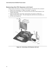
Observe the precautions in the notch. Remove the screw (Figure 19, A) that secures the card's metal bracket to remove the PCI Express x16 card from the connector (C). 4. Removing a PCI Express x16 Card 40 This will release the card from the connector: 1. Figure 19. Pull the card straight up. Push the card ejector lever down using the tip of a pencil or similar tool (Figure 19, B) in "Before You Begin" on page 25. 2. Intel Desktop Board DG33BU Product Guide Removing the PCI Express x16 Card Follow these instructions to the chassis back panel. 3.
Observe the precautions in the notch. Remove the screw (Figure 19, A) that secures the card's metal bracket to remove the PCI Express x16 card from the connector (C). 4. Removing a PCI Express x16 Card 40 This will release the card from the connector: 1. Figure 19. Pull the card straight up. Push the card ejector lever down using the tip of a pencil or similar tool (Figure 19, B) in "Before You Begin" on page 25. 2. Intel Desktop Board DG33BU Product Guide Removing the PCI Express x16 Card Follow these instructions to the chassis back panel. 3.
Product Guide
Page 45
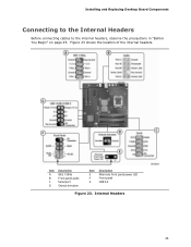
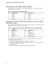
Figure 23 shows the location of the internal headers. Internal Headers 45 Installing and Replacing Desktop Board Components Connecting to the Internal Headers Before connecting cables to the internal headers, observe the precautions in "Before You Begin" on page 25. Item Description A IEEE 1394a B Front panel audio C Serial port D Chassis Intrusion Item Description E Alternate front panel power LED F Front panel G USB 2.0 Figure 23.
Figure 23 shows the location of the internal headers. Internal Headers 45 Installing and Replacing Desktop Board Components Connecting to the Internal Headers Before connecting cables to the internal headers, observe the precautions in "Before You Begin" on page 25. Item Description A IEEE 1394a B Front panel audio C Serial port D Chassis Intrusion Item Description E Alternate front panel power LED F Front panel G USB 2.0 Figure 23.
Product Guide
Page 46
..., B shows the location of the IEEE 1394a header. Front Panel Audio Header Signal Names for the location of the front panel audio header. Install a correctly keyed and shielded front panel audio cable. 46 Intel Desktop Board DG33BU Product Guide Connecting to the IEEE 1394a Header See Figure 23, A for Intel High Definition Audio Pin Signal Name 1 PORT 1L...
..., B shows the location of the IEEE 1394a header. Front Panel Audio Header Signal Names for the location of the front panel audio header. Install a correctly keyed and shielded front panel audio cable. 46 Intel Desktop Board DG33BU Product Guide Connecting to the IEEE 1394a Header See Figure 23, A for Intel High Definition Audio Pin Signal Name 1 PORT 1L...
Product Guide
Page 47
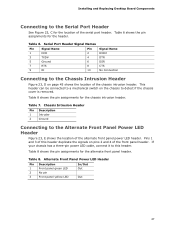
... duplicate the signals on the chassis to this header. Table 8 shows the pin assignments for the chassis intrusion header. Installing and Replacing Desktop Board Components Connecting to the Serial Port Header See Figure 23, C for the location of the front panel header. Table 7. Table 8. Table 6. Table 6 shows the pin assignments for the header.
... duplicate the signals on the chassis to this header. Table 8 shows the pin assignments for the chassis intrusion header. Installing and Replacing Desktop Board Components Connecting to the Serial Port Header See Figure 23, C for the location of the front panel header. Table 7. Table 8. Table 6. Table 6 shows the pin assignments for the header.
Product Guide
Page 48
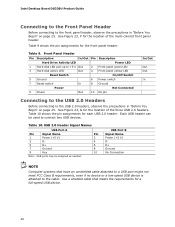
...1 Power (+5 V) 2 3 D- 4 5 D+ 6 7 Ground 8 9 Key 10 Note: USB ports may be used to connect two USB devices. Front Panel Header Pin Description In/Out Pin Description Hard Drive Activity LED Power LED 1 Hard disk LED pull-up to +5 V Out 3 Hard disk active LED Out..., F for the location of the multi-colored front panel header. See Figure 23, G for the location of the three USB 2.0 headers. Intel Desktop Board DG33BU Product Guide Connecting to the Front Panel Header Before connecting to the front panel header, observe the precautions in "Before You Begin" ...
...1 Power (+5 V) 2 3 D- 4 5 D+ 6 7 Ground 8 9 Key 10 Note: USB ports may be used to connect two USB devices. Front Panel Header Pin Description In/Out Pin Description Hard Drive Activity LED Power LED 1 Hard disk LED pull-up to +5 V Out 3 Hard disk active LED Out..., F for the location of the multi-colored front panel header. See Figure 23, G for the location of the three USB 2.0 headers. Intel Desktop Board DG33BU Product Guide Connecting to the Front Panel Header Before connecting to the front panel header, observe the precautions in "Before You Begin" ...
Product Guide
Page 49
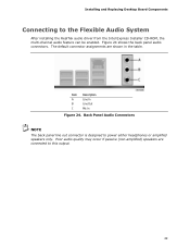
... System After installing the RealTek audio driver from the Intel Express Installer CD-ROM, the multi-channel audio feature can be enabled. The default connector assignments are connected to this output. 49 Figure 24 shows the back panel audio connectors. Installing and Replacing Desktop Board Components Connecting to power either headphones or amplified speakers...
... System After installing the RealTek audio driver from the Intel Express Installer CD-ROM, the multi-channel audio feature can be enabled. The default connector assignments are connected to this output. 49 Figure 24 shows the back panel audio connectors. Installing and Replacing Desktop Board Components Connecting to power either headphones or amplified speakers...


