Product Guide
Page 3
... manual: CAUTION Cautions warn the user about board layout, component installation, BIOS update, and regulatory requirements for general audiences. iii may not be supported without further evaluation by Intel. Preface This Product Guide gives information about how to prevent damage to hardware or loss of product features 2 Installing and Replacing Desktop Board Components: instructions on how to update the BIOS A Error Messages and Indicators: information about BIOS error messages and beep codes...
... manual: CAUTION Cautions warn the user about board layout, component installation, BIOS update, and regulatory requirements for general audiences. iii may not be supported without further evaluation by Intel. Preface This Product Guide gives information about how to prevent damage to hardware or loss of product features 2 Installing and Replacing Desktop Board Components: instructions on how to update the BIOS A Error Messages and Indicators: information about BIOS error messages and beep codes...
Product Guide
Page 5
... 10 Desktop Board Components 11 Processor ...13 Main Memory...13 Intel® G33 Express Chipset 14 Intel G33 Graphics Subsystem 14 Audio Subsystem 16 Legacy Input/Output (I/O) Controller 16 LAN Subsystem 17 RJ-45 LAN Connector LEDs 17 Hi-Speed USB 2.0 Support 18 Enhanced IDE Interface 18 Serial ATA...18 Expandability...18 BIOS ...18 Serial ATA and IDE Auto Configuration 19 PCI and PCI Express* Auto Configuration 19 Security Passwords 19 Hardware Management Features 19 Hardware Monitoring and Fan Speed Control 20 Chassis Intrusion 20 Power Management Features 20 ACPI...
... 10 Desktop Board Components 11 Processor ...13 Main Memory...13 Intel® G33 Express Chipset 14 Intel G33 Graphics Subsystem 14 Audio Subsystem 16 Legacy Input/Output (I/O) Controller 16 LAN Subsystem 17 RJ-45 LAN Connector LEDs 17 Hi-Speed USB 2.0 Support 18 Enhanced IDE Interface 18 Serial ATA...18 Expandability...18 BIOS ...18 Serial ATA and IDE Auto Configuration 19 PCI and PCI Express* Auto Configuration 19 Security Passwords 19 Hardware Management Features 19 Hardware Monitoring and Fan Speed Control 20 Chassis Intrusion 20 Power Management Features 20 ACPI...
Product Guide
Page 6
...a PCI Express x16 Card 39 Installing a PCI Express x16 Card 39 Removing the PCI Express x16 Card 40 Connecting the Diskette Drive Cable 41 Connecting the IDE Cable 42 Connecting the Serial ATA (SATA) Cables 44 Connecting to the Internal Headers 45 Connecting to the IEEE 1394a Header 46 Installing a Front Panel Audio Solution for Intel® High Definition Audio 46 Connecting to the Serial Port Header 47 Connecting to the Chassis Intrusion Header 47 Connecting to the Alternate Front Panel Power LED Header 47 Connecting to the Front Panel Header 48 Connecting to the USB 2.0 Headers...
...a PCI Express x16 Card 39 Installing a PCI Express x16 Card 39 Removing the PCI Express x16 Card 40 Connecting the Diskette Drive Cable 41 Connecting the IDE Cable 42 Connecting the Serial ATA (SATA) Cables 44 Connecting to the Internal Headers 45 Connecting to the IEEE 1394a Header 46 Installing a Front Panel Audio Solution for Intel® High Definition Audio 46 Connecting to the Serial Port Header 47 Connecting to the Chassis Intrusion Header 47 Connecting to the Alternate Front Panel Power LED Header 47 Connecting to the Front Panel Header 48 Connecting to the USB 2.0 Headers...
Product Guide
Page 7
.... Installing a PCI Express x16 Card 39 19. Connecting the Diskette Drive Cable 41 21. Location of the Standby Power Indicator 22 4. Removing the Battery 58 vii Installing a DIMM 37 18. Connecting a Serial ATA Cable 44 23. Internal Headers 45 24. Back Panel Audio Connectors 49 25. Connecting Power Supply Cables 51 27. Dual Channel Memory Configuration with Two DIMMs 34 14. Location of the Chassis Fan Headers 50 26. Lift the Socket Lever 29 7. Dual Channel Memory Configuration with Four DIMMs 35 15. Use DDR2 DIMMs 36 17. Removing a PCI Express...
.... Installing a PCI Express x16 Card 39 19. Connecting the Diskette Drive Cable 41 21. Location of the Standby Power Indicator 22 4. Removing the Battery 58 vii Installing a DIMM 37 18. Connecting a Serial ATA Cable 44 23. Internal Headers 45 24. Back Panel Audio Connectors 49 25. Connecting Power Supply Cables 51 27. Dual Channel Memory Configuration with Two DIMMs 34 14. Location of the Chassis Fan Headers 50 26. Lift the Socket Lever 29 7. Dual Channel Memory Configuration with Four DIMMs 35 15. Use DDR2 DIMMs 36 17. Removing a PCI Express...
Product Guide
Page 9
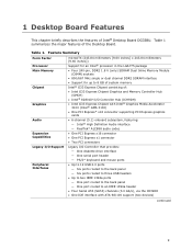
...One PCI Express* x16 connector supporting PCI Express graphics cards • 6-channel (5.1) onboard subsystem, featuring: ― Intel® High Definition Audio interface ― RealTek* ALC888 audio codec Expansion Capabilities • One PCI Express x16 connector • One PCI Express x1 connector • Two PCI connectors Legacy I/O Support Legacy I/O Controller that provides: ― One diskette drive interface ― One serial port header ― PS/2* keyboard and mouse ports Peripheral Interfaces • Up to 12 USB 2.0 ports ― Six ports routed to the back panel...
...One PCI Express* x16 connector supporting PCI Express graphics cards • 6-channel (5.1) onboard subsystem, featuring: ― Intel® High Definition Audio interface ― RealTek* ALC888 audio codec Expansion Capabilities • One PCI Express x16 connector • One PCI Express x1 connector • Two PCI connectors Legacy I/O Support Legacy I/O Controller that provides: ― One diskette drive interface ― One serial port header ― PS/2* keyboard and mouse ports Peripheral Interfaces • Up to 12 USB 2.0 ports ― Six ports routed to the back panel...
Product Guide
Page 10
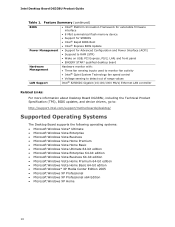
... panel • ENGERY STAR* qualified desktop board Hardware Management Hardware monitor with: • Three fan sensing inputs used to monitor fan activity • Intel® Quiet System Technology fan speed control • Voltage sensing to detect out of range values LAN Support Intel® 82566DC Gigabit (10/100/1000 Mb/s) Ethernet LAN controller Related Links: For more information about Desktop Board DG33BU, including the Technical Product Specification (TPS), BIOS updates, and device drivers, go to: http://support.intel.com/support/motherboards/desktop/ Supported...
... panel • ENGERY STAR* qualified desktop board Hardware Management Hardware monitor with: • Three fan sensing inputs used to monitor fan activity • Intel® Quiet System Technology fan speed control • Voltage sensing to detect out of range values LAN Support Intel® 82566DC Gigabit (10/100/1000 Mb/s) Ethernet LAN controller Related Links: For more information about Desktop Board DG33BU, including the Technical Product Specification (TPS), BIOS updates, and device drivers, go to: http://support.intel.com/support/motherboards/desktop/ Supported...
Product Guide
Page 12
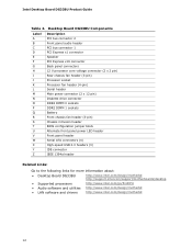
... pin) Diskette drive connector DDR2 DIMM 0 sockets DDR2 DIMM 1 sockets Battery Front chassis fan header (3-pin) Chassis intrusion header BIOS configuration jumper block Alternate front panel power LED header Front panel header Serial ATA connectors (4) High-speed USB 2.0 headers (3) IDE connector IEEE 1394a header Related Links: Go to the following links for more information about: • Desktop Board DG33BU http://www.intel.com/design/motherbd http://support.intel.com/support/motherboards/desktop • Supported processors • Audio software and utilities • LAN software and...
... pin) Diskette drive connector DDR2 DIMM 0 sockets DDR2 DIMM 1 sockets Battery Front chassis fan header (3-pin) Chassis intrusion header BIOS configuration jumper block Alternate front panel power LED header Front panel header Serial ATA connectors (4) High-speed USB 2.0 headers (3) IDE connector IEEE 1394a header Related Links: Go to the following links for more information about: • Desktop Board DG33BU http://www.intel.com/design/motherbd http://support.intel.com/support/motherboards/desktop • Supported processors • Audio software and utilities • LAN software and...
Product Guide
Page 14
... disabled. When a PCI Express x16 add-in card is installed, the Intel GMA 3100 graphics controller is used or a PCI Express x16 add-in Chapter 2 • Tested memory, http://www.cmtlabs.com/mbsearch.asp or http://www.intel.com/products/motherboard/index.htm?iid=HMPAGE+Header_2_P roduct_MB • PC Serial Presence Detect Specification, http://www.intel.com/technology/memory/ddr/specs/dda18c32_64_128x72aga.pdf Intel® G33 Express Chipset The Intel G33 Express Chipset consists of the following devices...
... disabled. When a PCI Express x16 add-in card is installed, the Intel GMA 3100 graphics controller is used or a PCI Express x16 add-in Chapter 2 • Tested memory, http://www.cmtlabs.com/mbsearch.asp or http://www.intel.com/products/motherboard/index.htm?iid=HMPAGE+Header_2_P roduct_MB • PC Serial Presence Detect Specification, http://www.intel.com/technology/memory/ddr/specs/dda18c32_64_128x72aga.pdf Intel® G33 Express Chipset The Intel G33 Express Chipset consists of the following devices...
Product Guide
Page 16
...8226; One serial port interface via an onboard header • One diskette drive interface • Serial IRQ interface compatible with serialized IRQ support for more information about: • Audio drivers and utilities http://support.intel.com/support/motherboards/desktop/ • Installing the front panel audio solution, page 46 • The location of 95 dB • Independent multi-streaming 5.1 audio (using the back panel audio connectors) and stereo (using the Intel High Definition front panel audio header). Intel Desktop Board DG33BU Product Guide Audio Subsystem The onboard audio...
...8226; One serial port interface via an onboard header • One diskette drive interface • Serial IRQ interface compatible with serialized IRQ support for more information about: • Audio drivers and utilities http://support.intel.com/support/motherboards/desktop/ • Installing the front panel audio solution, page 46 • The location of 95 dB • Independent multi-streaming 5.1 audio (using the back panel audio connectors) and stereo (using the Intel High Definition front panel audio header). Intel Desktop Board DG33BU Product Guide Audio Subsystem The onboard audio...
Product Guide
Page 17
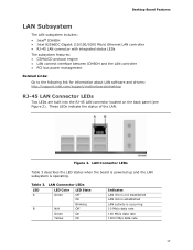
... protocol engine • LAN connect interface between ICH9DH and the LAN controller • PCI bus power management Related Links: Go to the following link for information about LAN software and drivers: http://support.intel.com/support/motherboards/desktop RJ-45 LAN Connector LEDs Two LEDs are built into the RJ-45 LAN connector located on the back panel (see Figure 2). LAN Connector LEDs Table 3 describes the LED states when the board is powered up and the LAN subsystem is occurring...
... protocol engine • LAN connect interface between ICH9DH and the LAN controller • PCI bus power management Related Links: Go to the following link for information about LAN software and drivers: http://support.intel.com/support/motherboards/desktop RJ-45 LAN Connector LEDs Two LEDs are built into the RJ-45 LAN connector located on the back panel (see Figure 2). LAN Connector LEDs Table 3 describes the LED states when the board is powered up and the LAN subsystem is occurring...
Product Guide
Page 18
Intel Desktop Board DG33BU Product Guide Hi-Speed USB 2.0 Support The Desktop Board supports up to 12 USB 2.0 ports (six ports routed to the back panel and six ports routed to USB 1.1 operation. The BIOS is stored in Chapter 3. 18 USB 2.0 ports are backward compatible with USB 1.1 devices. This may be updated by following expansion slots: • One PCI Express x16 connector • One PCI Express x1 connector • Two PCI bus connectors BIOS The BIOS provides the Power-On Self-Test (POST), the BIOS Setup program, the PCI/PCI Express and IDE auto-configuration utilities, and the...
Intel Desktop Board DG33BU Product Guide Hi-Speed USB 2.0 Support The Desktop Board supports up to 12 USB 2.0 ports (six ports routed to the back panel and six ports routed to USB 1.1 operation. The BIOS is stored in Chapter 3. 18 USB 2.0 ports are backward compatible with USB 1.1 devices. This may be updated by following expansion slots: • One PCI Express x16 connector • One PCI Express x1 connector • Two PCI bus connectors BIOS The BIOS provides the Power-On Self-Test (POST), the BIOS Setup program, the PCI/PCI Express and IDE auto-configuration utilities, and the...
Product Guide
Page 19
... be compatible with the following : • Fan speed monitoring and control • Thermal and voltage monitoring • Chassis intrusion detection 19 Security Passwords The BIOS includes security features that add-in card. You can be accessed and who can boot the computer. Desktop Board Features Serial ATA and IDE Auto Configuration If you install a Serial ATA or IDE device (such as a hard drive) in your computer, the auto-configuration utility in the BIOS Setup program. A supervisor password and a user password can override the auto-configuration options...
... be compatible with the following : • Fan speed monitoring and control • Thermal and voltage monitoring • Chassis intrusion detection 19 Security Passwords The BIOS includes security features that add-in card. You can be accessed and who can boot the computer. Desktop Board Features Serial ATA and IDE Auto Configuration If you install a Serial ATA or IDE device (such as a hard drive) in your computer, the auto-configuration utility in the BIOS Setup program. A supervisor password and a user password can override the auto-configuration options...
Product Guide
Page 20
... technology (Suspend to RAM) ⎯ +5 V standby power indicator LED ⎯ Wake from USB ⎯ Wake from PS/2 keyboard/mouse ⎯ Power Management Event signal (PME#) wakeup support ⎯ WAKE# signal wake-up support • ENERGY STAR qualified ACPI ACPI gives the operating system direct control over the power management and Plug and Play functions of a computer. Intel Desktop Board DG33BU Product Guide Hardware Monitoring and Fan Speed Control The features of the hardware monitoring and fan speed control include: • Monitoring of power supply voltages...
... technology (Suspend to RAM) ⎯ +5 V standby power indicator LED ⎯ Wake from USB ⎯ Wake from PS/2 keyboard/mouse ⎯ Power Management Event signal (PME#) wakeup support ⎯ WAKE# signal wake-up support • ENERGY STAR qualified ACPI ACPI gives the operating system direct control over the power management and Plug and Play functions of a computer. Intel Desktop Board DG33BU Product Guide Hardware Monitoring and Fan Speed Control The features of the hardware monitoring and fan speed control include: • Monitoring of power supply voltages...
Product Guide
Page 21
... 51 for the power supply must be capable of delivering adequate +5 V standby current. Desktop Board Features Hardware Support Power Connectors ATX12V-compliant power supplies can turn off the computer power through a network. The Desktop Board has a 4-pin processor fan header and two 3-pin chassis fan headers. LAN wakeup capabilities enable remote wake-up the computer. LAN Wake Capabilities CAUTION For LAN wake capabilities, the 5 V standby line for the location of the fans is in the BIOS Setup program's Boot menu. The LAN subsystem monitors network traffic and upon...
... 51 for the power supply must be capable of delivering adequate +5 V standby current. Desktop Board Features Hardware Support Power Connectors ATX12V-compliant power supplies can turn off the computer power through a network. The Desktop Board has a 4-pin processor fan header and two 3-pin chassis fan headers. LAN wakeup capabilities enable remote wake-up the computer. LAN Wake Capabilities CAUTION For LAN wake capabilities, the 5 V standby line for the location of the fans is in the BIOS Setup program's Boot menu. The LAN subsystem monitors network traffic and upon...
Product Guide
Page 22
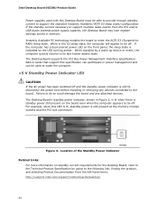
... to be off. Failure to do so could damage the board and any devices connected to the board. Intel Desktop Board DG33BU Product Guide Power supplies used to wake the computer. +5 V Standby Power Indicator LED CAUTION If the AC power has been switched off and the standby power indicator is still lit, disconnect the power cord before installing or removing any attached devices. Add-in cards that support this specification can participate in memory. When signaled by...
... to be off. Failure to do so could damage the board and any devices connected to the board. Intel Desktop Board DG33BU Product Guide Power supplies used to wake the computer. +5 V Standby Power Indicator LED CAUTION If the AC power has been switched off and the standby power indicator is still lit, disconnect the power cord before installing or removing any attached devices. Add-in cards that support this specification can participate in memory. When signaled by...
Product Guide
Page 25
... 2 Installing and Replacing Desktop Board Components This chapter tells you how to: • Install the I/O shield • Install and remove the Desktop Board • Install and remove a processor • Install and remove memory • Install and remove a PCI Express x16 card • Connect the diskette drive cable • Connect the IDE and Serial ATA cables • Connect to the internal headers • Connect to the flexible audio system • Connect chassis fan and power supply cables • Set the BIOS configuration jumper • Clear passwords • Replace the battery...
... 2 Installing and Replacing Desktop Board Components This chapter tells you how to: • Install the I/O shield • Install and remove the Desktop Board • Install and remove a processor • Install and remove memory • Install and remove a PCI Express x16 card • Connect the diskette drive cable • Connect the IDE and Serial ATA cables • Connect to the internal headers • Connect to the flexible audio system • Connect chassis fan and power supply cables • Set the BIOS configuration jumper • Clear passwords • Replace the battery...
Product Guide
Page 53
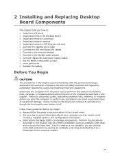
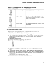
... and exit Setup. 53 Setup displays the Maintenance menu. 8. Turn off all peripheral devices connected to boot. 7. Replace the cover, plug in the computer and the configuration jumper block is installed in the computer, turn on the computer, and allow it to the computer. Setup displays the maintenance menu again. 9. Press and Setup displays a pop-up screen requesting that the board is set to select Clear Passwords. Installing and Replacing Desktop Board Components Table 11. Recovery (None) The BIOS recovers...
... and exit Setup. 53 Setup displays the Maintenance menu. 8. Turn off all peripheral devices connected to boot. 7. Replace the cover, plug in the computer and the configuration jumper block is installed in the computer, turn on the computer, and allow it to the computer. Setup displays the maintenance menu again. 9. Press and Setup displays a pop-up screen requesting that the board is set to select Clear Passwords. Installing and Replacing Desktop Board Components Table 11. Recovery (None) The BIOS recovers...
Product Guide
Page 59
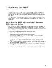
...; Flash Memory Update Utility and the ease of use of Windows-based installation wizards. This runs the update program. 6. Follow the instructions provided in the Windows environment. 3 Updating the BIOS The BIOS Setup program can be rebooted at the last Express BIOS Update window. 5. Updating the BIOS with the Intel Express BIOS Update utility: 1. Double-click the executable file from the location on your hard drive. (You can access the BIOS Setup program by either using the Intel Express BIOS Update utility or the Iflash Memory Update utility, and how to a removable USB device...
...; Flash Memory Update Utility and the ease of use of Windows-based installation wizards. This runs the update program. 6. Follow the instructions provided in the Windows environment. 3 Updating the BIOS The BIOS Setup program can be rebooted at the last Express BIOS Update window. 5. Updating the BIOS with the Intel Express BIOS Update utility: 1. Double-click the executable file from the location on your hard drive. (You can access the BIOS Setup program by either using the Intel Express BIOS Update utility or the Iflash Memory Update utility, and how to a removable USB device...
Product Guide
Page 60
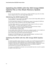
... BIOS file (including the Intel® Management Engine Firmware Image) • Intel® Integrator Toolkit Configuration File (optional) • Intel Flash Memory Update Utility You can be used to create a bootable CD that contains the files you need to update the BIOS using the ISO Image BIOS update file (recommended), or Iflash BIOS update file. It requires a blank CD-R, a read/writeable CD drive, and software capable of the BIOS by navigating to the Desktop Board DG33BU page on the computer's hard drive...
... BIOS file (including the Intel® Management Engine Firmware Image) • Intel® Integrator Toolkit Configuration File (optional) • Intel Flash Memory Update Utility You can be used to create a bootable CD that contains the files you need to update the BIOS using the ISO Image BIOS update file (recommended), or Iflash BIOS update file. It requires a blank CD-R, a read/writeable CD drive, and software capable of the BIOS by navigating to the Desktop Board DG33BU page on the computer's hard drive...
Product Guide
Page 62
... will interrupt the BIOS update; Configure the BIOS or use the F10 option during POST to boot to a bootable USB flash drive or other bootable USB media. 2. Due to : http://support.intel.com/support/motherboards/desktop/sb/CS-022312.htm 62 Recovering the BIOS It is unlikely that anything will be damaged. Related Links: For more information about updating the Intel Desktop Board BIOS or recovering from the USB device and manually update the BIOS. Intel Desktop Board DG33BU Product Guide CAUTION Do...
... will interrupt the BIOS update; Configure the BIOS or use the F10 option during POST to boot to a bootable USB flash drive or other bootable USB media. 2. Due to : http://support.intel.com/support/motherboards/desktop/sb/CS-022312.htm 62 Recovering the BIOS It is unlikely that anything will be damaged. Related Links: For more information about updating the Intel Desktop Board BIOS or recovering from the USB device and manually update the BIOS. Intel Desktop Board DG33BU Product Guide CAUTION Do...


