
Product Guide
Page 3
... Intel desktop boards are used in this manual: CAUTION Cautions warn the user about board layout, component installation, BIOS update, and regulatory requirements for installation in homes, offices, schools, computer rooms, and similar locations. Information Layout The chapters in this Product Guide are arranged as follows: 1 Desktop Board Features: a summary of product features 2 Installing and Replacing Desktop Board Components: instructions on how to install the desktop board and other environments, such as Information Technology Equipment (I.T.E.) for use...
... Intel desktop boards are used in this manual: CAUTION Cautions warn the user about board layout, component installation, BIOS update, and regulatory requirements for installation in homes, offices, schools, computer rooms, and similar locations. Information Layout The chapters in this Product Guide are arranged as follows: 1 Desktop Board Features: a summary of product features 2 Installing and Replacing Desktop Board Components: instructions on how to install the desktop board and other environments, such as Information Technology Equipment (I.T.E.) for use...

Product Guide
Page 5
...-Speed USB 2.0 Support 21 Enhanced IDE Interface ...21 Serial ATA...21 Expandability...21 BIOS ...22 Serial ATA and IDE Auto Configuration 22 PCI and PCI Express Auto Configuration 22 Security Passwords ...22 Chassis Intrusion...23 Power Management Features 23 ACPI...23 Power Connectors...23 Fan Connectors...23 Fan Speed Control (Intel® Precision Cooling Technology 23 Suspend to RAM (Instantly Available PC Technology 24 Wake from USB...24 Wake from PS/2 Keyboard/Mouse 25 PME# Wakeup Support 25 Speaker...25 Battery...25 Real-Time Clock...25 2 Installing and Replacing Desktop Board...
...-Speed USB 2.0 Support 21 Enhanced IDE Interface ...21 Serial ATA...21 Expandability...21 BIOS ...22 Serial ATA and IDE Auto Configuration 22 PCI and PCI Express Auto Configuration 22 Security Passwords ...22 Chassis Intrusion...23 Power Management Features 23 ACPI...23 Power Connectors...23 Fan Connectors...23 Fan Speed Control (Intel® Precision Cooling Technology 23 Suspend to RAM (Instantly Available PC Technology 24 Wake from USB...24 Wake from PS/2 Keyboard/Mouse 25 PME# Wakeup Support 25 Speaker...25 Battery...25 Real-Time Clock...25 2 Installing and Replacing Desktop Board...
Product Guide
Page 6
... 40 Removing the PCI Express x16 Card 40 Connecting the IDE Cable 41 Connecting the Serial ATA (SATA) Cable 42 Connecting Internal Headers 43 Installing a Front Panel Audio Solution for Intel® High Definition Audio 44 Connecting Hi-Speed USB 2.0 Headers 45 Connecting IEEE 1394a Headers (Optional 45 Connecting the Front Panel Header 46 Setting Up the Flexible 6-Channel Audio with Jack Re-tasking (Optional 47 Connecting Fan and Power Cables 48 Connecting Fan Cables 48 Connecting Power Cables 49 Other Connectors...50 Setting the BIOS Configuration Jumper 51 Clearing Passwords...
... 40 Removing the PCI Express x16 Card 40 Connecting the IDE Cable 41 Connecting the Serial ATA (SATA) Cable 42 Connecting Internal Headers 43 Installing a Front Panel Audio Solution for Intel® High Definition Audio 44 Connecting Hi-Speed USB 2.0 Headers 45 Connecting IEEE 1394a Headers (Optional 45 Connecting the Front Panel Header 46 Setting Up the Flexible 6-Channel Audio with Jack Re-tasking (Optional 47 Connecting Fan and Power Cables 48 Connecting Fan Cables 48 Connecting Power Cables 49 Other Connectors...50 Setting the BIOS Configuration Jumper 51 Clearing Passwords...

Product Guide
Page 7
.... Dual Configuration Example 3 37 17. Removing the Battery 57 28. F2 Key ...59 vii Location of Other Connectors on Desktop Board D945GNT/D945GTP 50 26. Desktop Board D945GNT Components 12 2. Desktop Board D945GNT/D945GTP Mounting Screw Hole Locations 31 7. Location of Fan Headers 48 24. Intel Desktop Board D945GTP Components 14 3. Lift the Load Plate and Don't Touch the Socket Contacts 32 9. Inserting a PCI Express x16 Card and Covering the Back Panel VGA Port 40 19. Connecting the IDE Cable 41...
.... Dual Configuration Example 3 37 17. Removing the Battery 57 28. F2 Key ...59 vii Location of Other Connectors on Desktop Board D945GNT/D945GTP 50 26. Desktop Board D945GNT Components 12 2. Desktop Board D945GNT/D945GTP Mounting Screw Hole Locations 31 7. Location of Fan Headers 48 24. Intel Desktop Board D945GTP Components 14 3. Lift the Load Plate and Don't Touch the Socket Contacts 32 9. Inserting a PCI Express x16 Card and Covering the Back Panel VGA Port 40 19. Connecting the IDE Cable 41...
Product Guide
Page 9
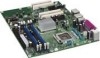
... Factors Processor Main Memory Chipset Graphics Audio Expansion Capabilities • ATX (12.00" x 9.60") desktop board D945GNT • MicroATX (9.60" x 9.60") desktop board D945GTP Support for an Intel® processor in the LGA775 package • Four 240-pin, 1.8 V SDRAM Dual Inline Memory Module (DIMM) sockets • 667/533/400 MHz single or dual channel DDR2 SDRAM interface • Designed to support up to 4 GB of memory being available to PCI bus 2) • One PCI Express x16 connector...
... Factors Processor Main Memory Chipset Graphics Audio Expansion Capabilities • ATX (12.00" x 9.60") desktop board D945GNT • MicroATX (9.60" x 9.60") desktop board D945GTP Support for an Intel® processor in the LGA775 package • Four 240-pin, 1.8 V SDRAM Dual Inline Memory Module (DIMM) sockets • 667/533/400 MHz single or dual channel DDR2 SDRAM interface • Designed to support up to 4 GB of memory being available to PCI bus 2) • One PCI Express x16 connector...
Product Guide
Page 10
... for extensible firmware interface • 4 Mbit symmetrical flash memory • Support for SMBIOS • Intel® Rapid BIOS Boot • Intel® Express BIOS Update Power Management • Support for Advanced Configuration and Power Interface (ACPI) • Suspend to RAM (STR) • Wake on USB, PCI, PCI Express, PS/2, LAN, and front panel Hardware Management Hardware monitor with: • Three fan sensing inputs used to monitor fan activity • Remote diode temperature sensing • Intel® Precision Cooling Technology fan speed control • Voltage sensing...
... for extensible firmware interface • 4 Mbit symmetrical flash memory • Support for SMBIOS • Intel® Rapid BIOS Boot • Intel® Express BIOS Update Power Management • Support for Advanced Configuration and Power Interface (ACPI) • Suspend to RAM (STR) • Wake on USB, PCI, PCI Express, PS/2, LAN, and front panel Hardware Management Hardware monitor with: • Three fan sensing inputs used to monitor fan activity • Remote diode temperature sensing • Intel® Precision Cooling Technology fan speed control • Voltage sensing...
Product Guide
Page 13
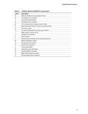
..., fan speed control) PCI Express x1 connectors Front panel audio header PCI Express x16 connector 12 V processor core voltage connector (2x2) Rear chassis fan header 1 (3-pin, fan speed control) Processor socket Processor fan header (4-pin, fan speed control) Main power connector (2x12) Diskette drive connector IDE connector Front chassis fan header (3-pin, fan speed control) BIOS configuration jumper Chassis intrusion header Serial ATA connectors Front panel header Alternate power LED header Hi-speed USB 2.0 headers IEEE 1394a headers (optional) PCI bus add-in card connectors Desktop Board...
..., fan speed control) PCI Express x1 connectors Front panel audio header PCI Express x16 connector 12 V processor core voltage connector (2x2) Rear chassis fan header 1 (3-pin, fan speed control) Processor socket Processor fan header (4-pin, fan speed control) Main power connector (2x12) Diskette drive connector IDE connector Front chassis fan header (3-pin, fan speed control) BIOS configuration jumper Chassis intrusion header Serial ATA connectors Front panel header Alternate power LED header Hi-speed USB 2.0 headers IEEE 1394a headers (optional) PCI bus add-in card connectors Desktop Board...

Product Guide
Page 15
...S Desktop Boards D945GTP Components Description Front panel audio header PCI bus add-in card connectors PCI Express x16 connector 12 V processor core voltage connector (2x2) Rear fan (3-pin, fan speed control) Processor socket Processor fan header (4-pin, fan speed control) Main power connector (2x12) Diskette drive connector IDE connector Front chassis fan header (fan speed control) BIOS configuration jumper Chassis intrusion header Serial ATA connectors Front panel header Alternate power LED header Hi-speed USB 2.0 headers IEEE 1394 headers (optional) PCI Express x1 connector Related Links...
...S Desktop Boards D945GTP Components Description Front panel audio header PCI bus add-in card connectors PCI Express x16 connector 12 V processor core voltage connector (2x2) Rear fan (3-pin, fan speed control) Processor socket Processor fan header (4-pin, fan speed control) Main power connector (2x12) Diskette drive connector IDE connector Front chassis fan header (fan speed control) BIOS configuration jumper Chassis intrusion header Serial ATA connectors Front panel header Alternate power LED header Hi-speed USB 2.0 headers IEEE 1394 headers (optional) PCI Express x1 connector Related Links...
Product Guide
Page 17
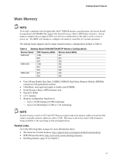
... and applications. If your memory modules do not support SPD, you will attempt to configure the memory controller for more information about: • The latest list of memory being available to this effect on the screen at power up. This may result in less than 4 GB of tested memory, http://support.intel.com/support/motherboards/desktop/ • SDRAM specifications, http://www.intel.com/technology/memory/ • Installing memory, page 36 in...
... and applications. If your memory modules do not support SPD, you will attempt to configure the memory controller for more information about: • The latest list of memory being available to this effect on the screen at power up. This may result in less than 4 GB of tested memory, http://support.intel.com/support/motherboards/desktop/ • SDRAM specifications, http://www.intel.com/technology/memory/ • Installing memory, page 36 in...
Product Guide
Page 21
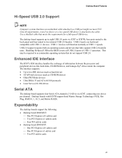
... internal USB 2.0 headers. Use a shielded cable that fully support USB 2.0 transfer rates. USB 2.0 ports are backward compatible with ICH7R support Intel Matrix Storage Technology (NCQ, Hot Plug, RAID 0, 1, 10, 5, and Matrix RAID). four ports routed to the back panel and four routed to two IDE devices (such as hard drives) • ATAPI-style devices (such as CD-ROM drives) • Older PIO Mode devices • Ultra DMA-33 and ATA-66/100 protocols • Laser Servo (LS-120) drives Serial...
... internal USB 2.0 headers. Use a shielded cable that fully support USB 2.0 transfer rates. USB 2.0 ports are backward compatible with ICH7R support Intel Matrix Storage Technology (NCQ, Hot Plug, RAID 0, 1, 10, 5, and Matrix RAID). four ports routed to the back panel and four routed to two IDE devices (such as hard drives) • ATAPI-style devices (such as CD-ROM drives) • Older PIO Mode devices • Ultra DMA-33 and ATA-66/100 protocols • Laser Servo (LS-120) drives Serial...

Product Guide
Page 22
... and change all Setup options. Related Links: For instructions on resetting the password, see page 40 in Chapter 3. You do not need to run the BIOS Setup program after installing a Serial ATA or IDE device. The password prompt is displayed before the computer is stored in card. Intel Desktop Board D945GNT/D945GTP Product Guide Related Links: For information about installing the PCI Express x16 card, see Clearing Passwords on page 52. 22 Serial ATA and IDE Auto Configuration If...
... and change all Setup options. Related Links: For instructions on resetting the password, see page 40 in Chapter 3. You do not need to run the BIOS Setup program after installing a Serial ATA or IDE device. The password prompt is displayed before the computer is stored in card. Intel Desktop Board D945GNT/D945GTP Product Guide Related Links: For information about installing the PCI Express x16 card, see Clearing Passwords on page 52. 22 Serial ATA and IDE Auto Configuration If...
Product Guide
Page 23
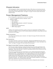
... if a self-controlled chassis fan is not a self controlled fan. Fan Connectors The desktop board has a 4-pin processor fan header. Desktop board D945GTP has two chassis fan headers (two 3-pin). Disabling the chassis fan speed control results in the fan operating at several levels, including: • Advanced Configuration and Power Interface (ACPI) • Hardware support: ⎯ Power connectors ⎯ Fan connectors ⎯ Suspend to RAM (Instantly Available PC technology) ⎯ Wake from USB ⎯ Wake from PS/2 keyboard/mouse ⎯ PME# wakeup support ACPI ACPI gives the...
... if a self-controlled chassis fan is not a self controlled fan. Fan Connectors The desktop board has a 4-pin processor fan header. Desktop board D945GTP has two chassis fan headers (two 3-pin). Disabling the chassis fan speed control results in the fan operating at several levels, including: • Advanced Configuration and Power Interface (ACPI) • Hardware support: ⎯ Power connectors ⎯ Fan connectors ⎯ Suspend to RAM (Instantly Available PC technology) ⎯ Wake from USB ⎯ Wake from PS/2 keyboard/mouse ⎯ PME# wakeup support ACPI ACPI gives the...

Product Guide
Page 24
... by the LED turning amber. USB bus activity wakes the computer from the PCI and/or USB buses exceeds power supply capacity, the desktop board may lose register settings stored in memory. Instantly Available PC technology enables the board to enter the ACPI S3 (Suspend-to support multiple wake events from an ACPI S1 or S3 state. 24 If the system has a dual-colored power LED on standby current requirements for the power supply must be...
... by the LED turning amber. USB bus activity wakes the computer from the PCI and/or USB buses exceeds power supply capacity, the desktop board may lose register settings stored in memory. Instantly Available PC technology enables the board to enter the ACPI S3 (Suspend-to support multiple wake events from an ACPI S1 or S3 state. 24 If the system has a dual-colored power LED on standby current requirements for the power supply must be...

Product Guide
Page 27
...and from any telecommunications links, networks, or modems before you how to: • Install the I/O shield • Install and remove the desktop board • Install and remove a processor and memory • Install and remove a PCI Express x16 card • Connect the IDE and Serial ATA cables • Connect internal headers • Set up flexible 6-channel audio with jack re-tasking • Connect fans and power cables • Locate other connectors • Set the BIOS configuration jumper • Clear passwords • Replace the battery Before You Begin CAUTIONS The procedures...
...and from any telecommunications links, networks, or modems before you how to: • Install the I/O shield • Install and remove the desktop board • Install and remove a processor and memory • Install and remove a PCI Express x16 card • Connect the IDE and Serial ATA cables • Connect internal headers • Set up flexible 6-channel audio with jack re-tasking • Connect fans and power cables • Locate other connectors • Set the BIOS configuration jumper • Clear passwords • Replace the battery Before You Begin CAUTIONS The procedures...
Product Guide
Page 36
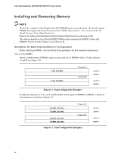
.../technology/memory/ddr/specs/dda18c32_64_128x72ag_a.pdf The desktop board has four 240-pin DDR2 DIMM sockets arranged as DIMM 0 (blue) and DIMM 1 (black) in both channels A and B (see Figure 14). 1 GB, 533 MHz 1 GB, 533 MHz Channel A Channel B DIMM 0 DIMM 1 DIMM 0 DIMM 1 Figure 14. Dual Configuration Example 1 If additional memory is to be fully compliant with all applicable Intel SDRAM memory specifications, the boards require DIMMs that support the Serial...
.../technology/memory/ddr/specs/dda18c32_64_128x72ag_a.pdf The desktop board has four 240-pin DDR2 DIMM sockets arranged as DIMM 0 (blue) and DIMM 1 (black) in both channels A and B (see Figure 14). 1 GB, 533 MHz 1 GB, 533 MHz Channel A Channel B DIMM 0 DIMM 1 DIMM 0 DIMM 1 Figure 14. Dual Configuration Example 1 If additional memory is to be fully compliant with all applicable Intel SDRAM memory specifications, the boards require DIMMs that support the Serial...

Product Guide
Page 51
...the power on may result in BIOS Setup. Location of the BIOS Configuration Jumper OM17624 The three-pin BIOS jumper enables all board configurations to clear passwords. 1 Recovery (None) The BIOS recovers data from the computer before changing the jumper. Jumper Settings for the BIOS Setup Program Modes Jumper Setting 3 Mode Normal (default) (1-2) Description The BIOS uses the current configuration and passwords for the Setup program modes. Table 14 shows the jumper settings for booting. 1 Configure (2-3) After the Power-On Self-Test (POST) runs, the BIOS 3 displays the...
...the power on may result in BIOS Setup. Location of the BIOS Configuration Jumper OM17624 The three-pin BIOS jumper enables all board configurations to clear passwords. 1 Recovery (None) The BIOS recovers data from the computer before changing the jumper. Jumper Settings for the BIOS Setup Program Modes Jumper Setting 3 Mode Normal (default) (1-2) Description The BIOS uses the current configuration and passwords for the Setup program modes. Table 14 shows the jumper settings for booting. 1 Configure (2-3) After the Power-On Self-Test (POST) runs, the BIOS 3 displays the...

Product Guide
Page 52
...'s power cord from the AC power source (wall outlet or power adapter). 3. Intel Desktop Board D945GNT/D945GTP Product Guide Clearing Passwords This procedure assumes that you confirm clearing the password. Select Yes and press . Setup displays the Maintenance menu. 8. Press and Setup displays a pop-up screen requesting that the board is installed in the computer, and turn on page 27. 2. Replace the cover, plug in the computer and the configuration jumper block is set to boot...
...'s power cord from the AC power source (wall outlet or power adapter). 3. Intel Desktop Board D945GNT/D945GTP Product Guide Clearing Passwords This procedure assumes that you confirm clearing the password. Select Yes and press . Setup displays the Maintenance menu. 8. Press and Setup displays a pop-up screen requesting that the board is installed in the computer, and turn on page 27. 2. Replace the cover, plug in the computer and the configuration jumper block is set to boot...
Product Guide
Page 59
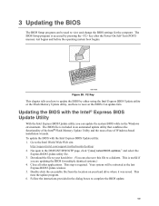
... the key after the Power-On Self-Test (POST) memory test begins and before the operating system boot begins. This runs the update program. 6. The BIOS file is accessed by either using the Intel Express BIOS Update utility or the Iflash Memory Update utility, and how to your hard drive where it was saved. Download the file to recover the BIOS if an update fails. Double-click the executable file from the location on your hard drive. (You...
... the key after the Power-On Self-Test (POST) memory test begins and before the operating system boot begins. This runs the update program. 6. The BIOS file is accessed by either using the Intel Express BIOS Update utility or the Iflash Memory Update utility, and how to your hard drive where it was saved. Download the file to recover the BIOS if an update fails. Double-click the executable file from the location on your hard drive. (You...

Product Guide
Page 63
... key after the Power-On-Self-Test (POST) memory tests begin. 3. Optional Requires Microsoft Windows* XP or 2000 and SATA Hard Drive(s) Configuring the BIOS for RAID (Intel® Matrix Storage Technology) - Enter system BIOS Setup by pressing . Select the drives to Create Volume. 8. Finally, press to be in English alphanumeric ASCII characters. 3. Upon re-boot, you will only appear if three or four SATA drives are more SATA hard drives. 2. In the Intel Matrix Storage Manager option ROM Main Menu...
... key after the Power-On-Self-Test (POST) memory tests begin. 3. Optional Requires Microsoft Windows* XP or 2000 and SATA Hard Drive(s) Configuring the BIOS for RAID (Intel® Matrix Storage Technology) - Enter system BIOS Setup by pressing . Select the drives to Create Volume. 8. Finally, press to be in English alphanumeric ASCII characters. 3. Upon re-boot, you will only appear if three or four SATA drives are more SATA hard drives. 2. In the Intel Matrix Storage Manager option ROM Main Menu...

Product Guide
Page 64
...the Intel Express Installer CD included with your desktop board or after downloading it from the Windows installation CD. 2. Begin Windows Setup by booting from the Internet at http://support.intel.com/support/motherboards/desktop/. Intel Desktop Board D945GNT/D945GTP Product Guide Loading the Intel Matrix Storage Technology RAID Drivers and Software 1. Setting Up a "RAID Ready" System The Intel Matrix Storage Technology Console software offers the flexibility to upgrade from this section: "Configuring the BIOS for Intel Matrix Storage Technology" and "Loading the Intel Matrix Storage...
...the Intel Express Installer CD included with your desktop board or after downloading it from the Windows installation CD. 2. Begin Windows Setup by booting from the Internet at http://support.intel.com/support/motherboards/desktop/. Intel Desktop Board D945GNT/D945GTP Product Guide Loading the Intel Matrix Storage Technology RAID Drivers and Software 1. Setting Up a "RAID Ready" System The Intel Matrix Storage Technology Console software offers the flexibility to upgrade from this section: "Configuring the BIOS for Intel Matrix Storage Technology" and "Loading the Intel Matrix Storage...


