
User Manual
Page 3
... Layout The chapters in this Product Guide are used in this manual: WARNING Warnings indicate conditions that, if not observed, can cause personal injury. CAUTION Cautions warn the user about BIOS error messages and beep codes B Regulatory Compliance: safety and EMC regulations, product certification Conventions The following conventions are arranged as follows: 1 Desktop Board Features: a summary of product features 2 Installing and Replacing Desktop Board Components: instructions...
... Layout The chapters in this Product Guide are used in this manual: WARNING Warnings indicate conditions that, if not observed, can cause personal injury. CAUTION Cautions warn the user about BIOS error messages and beep codes B Regulatory Compliance: safety and EMC regulations, product certification Conventions The following conventions are arranged as follows: 1 Desktop Board Features: a summary of product features 2 Installing and Replacing Desktop Board Components: instructions...
User Manual
Page 6
... (SATA) Cable 43 Connecting Internal Headers 44 Installing a Front Panel Audio Solution 45 Connecting USB 2.0 Headers 46 Connecting the Front Panel Header 46 Setting Up the Flexible 6-Channel Audio with Jack Re-tasking 47 Connecting Fan and Power Cables 48 Connecting Fan Cables 48 Connecting Power Cables 49 PCI Bus Add-In Card Connectors 51 Setting the BIOS Configuration Jumper Block 52 Clearing Passwords ...53 Back Panel Connectors...54 Replacing the Battery...55 3 BIOS Updating the BIOS with the Intel® Express BIOS Update Utility 59 Updating the BIOS with the Iflash Memory...
... (SATA) Cable 43 Connecting Internal Headers 44 Installing a Front Panel Audio Solution 45 Connecting USB 2.0 Headers 46 Connecting the Front Panel Header 46 Setting Up the Flexible 6-Channel Audio with Jack Re-tasking 47 Connecting Fan and Power Cables 48 Connecting Fan Cables 48 Connecting Power Cables 49 PCI Bus Add-In Card Connectors 51 Setting the BIOS Configuration Jumper Block 52 Clearing Passwords ...53 Back Panel Connectors...54 Replacing the Battery...55 3 BIOS Updating the BIOS with the Intel® Express BIOS Update Utility 59 Updating the BIOS with the Iflash Memory...
User Manual
Page 16
Intel Desktop Board D915GEV/D915GUX/D915GAV/D915GAG Product Guide Processor CAUTION Failure to use an ATX12V power supply, or not connecting the 12 V (2x2) processor core voltage power supply connector to Desktop Board D915GEV/D915GUX/D915GAV/D915GAG may result in damage to the following links or pages for more information about: • Supported Intel processors for Desktop Boards D915GEV, D915GUX, D915GAV, and D915GAG is located on installing or upgrading the processor, page 32 in Chapter 2 • The location of the two power connectors, page...
Intel Desktop Board D915GEV/D915GUX/D915GAV/D915GAG Product Guide Processor CAUTION Failure to use an ATX12V power supply, or not connecting the 12 V (2x2) processor core voltage power supply connector to Desktop Board D915GEV/D915GUX/D915GAV/D915GAG may result in damage to the following links or pages for more information about: • Supported Intel processors for Desktop Boards D915GEV, D915GUX, D915GAV, and D915GAG is located on installing or upgrading the processor, page 32 in Chapter 2 • The location of the two power connectors, page...
User Manual
Page 22
... (POST), the BIOS Setup program, the PCI/PCI Express and IDE auto-configuration utilities, and the video BIOS. Serial ATA and IDE Auto Configuration If you install a Serial ATA or IDE device (such as CD-ROM drives) • Older PIO Mode devices • Ultra DMA-33 and ATA-66/100 protocols • Laser Servo (LS-120) drives Serial ATA The desktop boards support four Serial ATA channels via ICH6, connecting one device per channel. You can be updated by specifying manual configuration in the BIOS Setup program. 22 The BIOS...
... (POST), the BIOS Setup program, the PCI/PCI Express and IDE auto-configuration utilities, and the video BIOS. Serial ATA and IDE Auto Configuration If you install a Serial ATA or IDE device (such as CD-ROM drives) • Older PIO Mode devices • Ultra DMA-33 and ATA-66/100 protocols • Laser Servo (LS-120) drives Serial ATA The desktop boards support four Serial ATA channels via ICH6, connecting one device per channel. You can be updated by specifying manual configuration in the BIOS Setup program. 22 The BIOS...
User Manual
Page 27
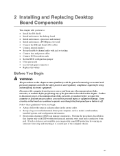
... Connect fans and power cables • Connect PCI bus add-in cards • Set the BIOS configuration jumper • Clear passwords • Locate back panel connectors • Replace the battery Before You Begin WARNINGS The procedures in this chapter. 2 Installing and Replacing Desktop Board Components This chapter tells you how to: • Install the I/O shield • Install and remove the desktop board • Install and remove a processor and memory • Install and remove a PCI Express x16 card • Connect the IDE and Serial ATA cables • Connect internal headers...
... Connect fans and power cables • Connect PCI bus add-in cards • Set the BIOS configuration jumper • Clear passwords • Locate back panel connectors • Replace the battery Before You Begin WARNINGS The procedures in this chapter. 2 Installing and Replacing Desktop Board Components This chapter tells you how to: • Install the I/O shield • Install and remove the desktop board • Install and remove a processor and memory • Install and remove a PCI Express x16 card • Connect the IDE and Serial ATA cables • Connect internal headers...

User Manual
Page 52
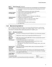
... three-pin BIOS jumper block enables all board configurations to clear passwords. Table 12 shows the jumper settings for booting. 1 3 1 3 Configure (2-3) Recovery (None) After the Power-On Self-Test (POST) runs, the BIOS displays the Maintenance Menu. Use this menu to be done in BIOS Setup. Intel Desktop Board D915GEV/D915GUX/D915GAV/D915GAG Product Guide Setting the BIOS Configuration Jumper Block CAUTION Always turn off the power and unplug the power cord from a recovery diskette in the event of a failed BIOS update. 52 Location of the desktop board's BIOS configuration jumper...
... three-pin BIOS jumper block enables all board configurations to clear passwords. Table 12 shows the jumper settings for booting. 1 3 1 3 Configure (2-3) Recovery (None) After the Power-On Self-Test (POST) runs, the BIOS displays the Maintenance Menu. Use this menu to be done in BIOS Setup. Intel Desktop Board D915GEV/D915GUX/D915GAV/D915GAG Product Guide Setting the BIOS Configuration Jumper Block CAUTION Always turn off the power and unplug the power cord from a recovery diskette in the event of a failed BIOS update. 52 Location of the desktop board's BIOS configuration jumper...

User Manual
Page 67
... be located on a removable media and stored in a secure location when not in use. 16. These passwords should be configured. To backup the keys for the EMBASSY Trust Suite, the Key Transfer Manager software must be copied to the TPM. Upon completing the configuration of the platform. 9. Recovery Procedures How to Recover from Hard Disk Failure Restore the latest hard drive image from the program menu. 15...
... be located on a removable media and stored in a secure location when not in use. 16. These passwords should be configured. To backup the keys for the EMBASSY Trust Suite, the Key Transfer Manager software must be copied to the TPM. Upon completing the configuration of the platform. 9. Recovery Procedures How to Recover from Hard Disk Failure Restore the latest hard drive image from the program menu. 15...
User Manual
Page 74
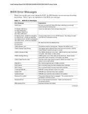
... Pri Slave Drive - Replace the battery soon. Checking NVRAM..... Table 17. Pri Master HDD Error Pri Slave HDD Error Sec Master HDD Error Sec Slave HDD Error Could not read /write test of the BIOS error messages. ATAPI Incompatible Corresponding drive is valid. CMOS Display Type Wrong The display type is engaged. Run Setup to access hard disk controller. HDC Failure Error occurred trying to reset values. The system must be updated. ATAPI Incompatible Sec Slave Drive - CMOS Settings Wrong CMOS values...
... Pri Slave Drive - Replace the battery soon. Checking NVRAM..... Table 17. Pri Master HDD Error Pri Slave HDD Error Sec Master HDD Error Sec Slave HDD Error Could not read /write test of the BIOS error messages. ATAPI Incompatible Corresponding drive is valid. CMOS Display Type Wrong The display type is engaged. Run Setup to access hard disk controller. HDC Failure Error occurred trying to reset values. The system must be updated. ATAPI Incompatible Sec Slave Drive - CMOS Settings Wrong CMOS values...
Product Specification
Page 13
... internal CD-ROM drive to the onboard audio subsystem ATX fan connector Additional fan connector for use in larger chassis (D915GAV board only) IEEE-1394a Interface IEEE-1394a controller and three IEEE-1394a connectors (one back panel connector, two front-panel connectors) LAN subsystem The D915GAG board provides one on the D915GAG) • One PCI Express x16 bus add-in card connector (both boards) Instantly Available PC Technology • Support for PCI Local Bus Specification Revision 2.2 • Support for PCI Express Revision 1.0a • Suspend to RAM support • Wake...
... internal CD-ROM drive to the onboard audio subsystem ATX fan connector Additional fan connector for use in larger chassis (D915GAV board only) IEEE-1394a Interface IEEE-1394a controller and three IEEE-1394a connectors (one back panel connector, two front-panel connectors) LAN subsystem The D915GAG board provides one on the D915GAG) • One PCI Express x16 bus add-in card connector (both boards) Instantly Available PC Technology • Support for PCI Local Bus Specification Revision 2.2 • Support for PCI Express Revision 1.0a • Suspend to RAM support • Wake...
Product Specification
Page 18
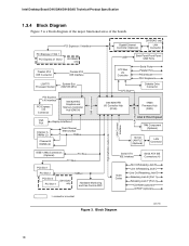
... PCI Express x1 Slot 1 PCI Express x1 Slot 2 D915GAV only Parallel ATA IDE Connector Parallel ATA IDE Interface LGA775 Processor Socket System Bus (800/533 MHz) PCI Express x16 Interface PCI Express x16 Connector Intel 82915G Graphics and Memory Controller Hub (GMCH) VGA Port Channel A DIMMs (2) Display Interface Dual-Channel Memory Bus SMBus Channel B DIMMs (2) Gigabit Ethernet Controller (Optional) D915GAG only LAN Connector USB Back Panel/Front Panel USB Ports LPC Bus I/O Controller LPC Bus Serial Ports Parallel Port PS/2 Mouse PS/2 Keyboard Diskette Drive Connector Intel...
... PCI Express x1 Slot 1 PCI Express x1 Slot 2 D915GAV only Parallel ATA IDE Connector Parallel ATA IDE Interface LGA775 Processor Socket System Bus (800/533 MHz) PCI Express x16 Interface PCI Express x16 Connector Intel 82915G Graphics and Memory Controller Hub (GMCH) VGA Port Channel A DIMMs (2) Display Interface Dual-Channel Memory Bus SMBus Channel B DIMMs (2) Gigabit Ethernet Controller (Optional) D915GAG only LAN Connector USB Back Panel/Front Panel USB Ports LPC Bus I/O Controller LPC Bus Serial Ports Parallel Port PS/2 Mouse PS/2 Keyboard Diskette Drive Connector Intel...
Product Specification
Page 30
... Drive Activity LED Connector (Optional) The SCSI hard drive activity LED connector is a 1 x 2-pin connector that the underlying PCI Express architecture is compatible with PCI Conventional compliant operating systems. Additional features of the PCI Express interface include the following PCI Express connectors: • One PCI Express x16 connector supporting simultaneous transfer speeds up to 500 MBytes/sec The PCI Express interface supports the PCI Conventional bus configuration mechanism so that allows an add-in hard drive controller to use the same LED as the onboard IDE controller...
... Drive Activity LED Connector (Optional) The SCSI hard drive activity LED connector is a 1 x 2-pin connector that the underlying PCI Express architecture is compatible with PCI Conventional compliant operating systems. Additional features of the PCI Express interface include the following PCI Express connectors: • One PCI Express x16 connector supporting simultaneous transfer speeds up to 500 MBytes/sec The PCI Express interface supports the PCI Conventional bus configuration mechanism so that allows an add-in hard drive controller to use the same LED as the onboard IDE controller...
Product Specification
Page 91
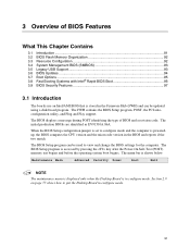
... BIOS Setup program, POST, the PCI autoconfiguration utility, and Plug and Play support. The BIOS Setup program can be used to configure mode and the computer is poweredup, the BIOS compares the CPU version and the microcode version in configure mode. 91 The BIOS Setup program is shown below. When the BIOS Setup configuration jumper is set to view and change the BIOS settings for the computer. Maintenance Main Advanced Security Power Boot Exit NOTE The maintenance menu is displayed only when the Desktop Board...
... BIOS Setup program, POST, the PCI autoconfiguration utility, and Plug and Play support. The BIOS Setup program can be used to configure mode and the computer is poweredup, the BIOS compares the CPU version and the microcode version in configure mode. 91 The BIOS Setup program is shown below. When the BIOS Setup configuration jumper is set to view and change the BIOS settings for the computer. Maintenance Main Advanced Security Power Boot Exit NOTE The maintenance menu is displayed only when the Desktop Board...
Product Specification
Page 92
.../100 and recognizes any ATAPI compliant devices, including CD-ROM drives, tape drives, and Ultra DMA drives. Table 46. BIOS Setup Program Menu Bar Maintenance Main Advanced Security Clears passwords and displays processor information Displays processor and memory configuration Configures advanced features available through the chipset Sets passwords and security features Power Boot Configures power management features and power supply controls Selects boot options Exit Saves or discards changes to configure the system. The IDE interface supports hard drives up or down) Selects...
.../100 and recognizes any ATAPI compliant devices, including CD-ROM drives, tape drives, and Ultra DMA drives. Table 46. BIOS Setup Program Menu Bar Maintenance Main Advanced Security Clears passwords and displays processor information Displays processor and memory configuration Configures advanced features available through the chipset Sets passwords and security features Power Boot Configures power management features and power supply controls Selects boot options Exit Saves or discards changes to configure the system. The IDE interface supports hard drives up or down) Selects...
Product Specification
Page 93
... as memory size, cache size, and processor speed • Dynamic data, such as event detection and error logging Non-Plug and Play operating systems, such as third-party management software to enter and configure the BIOS Setup program and the maintenance menu. 4. Legacy USB support is a Desktop Management Interface (DMI) compliant method for managing computers in the BIOS Setup program. The main component of the drive. The BIOS enables applications such as Windows NT...
... as memory size, cache size, and processor speed • Dynamic data, such as event detection and error logging Non-Plug and Play operating systems, such as third-party management software to enter and configure the BIOS Setup program and the maintenance menu. 4. Legacy USB support is a Desktop Management Interface (DMI) compliant method for managing computers in the BIOS Setup program. The main component of the drive. The BIOS enables applications such as Windows NT...

Product Specification
Page 101
... left at port 80h. Keyboard controller BAT test, CPU ID saved, and going to main BIOS in F000 shadow RAM. Do necessary chipset initialization, start memory refresh, and do memory sizing. Verify base memory. Copy main BIOS image to F000 shadow RAM and give control to check point E9). 101 Initialize floppy drive. If reading of POST Operation Onboard Floppy Controller (if any) is useful for ATAPI (LS-120, Zip) devices. Retry the booting procedure again...
... left at port 80h. Keyboard controller BAT test, CPU ID saved, and going to main BIOS in F000 shadow RAM. Do necessary chipset initialization, start memory refresh, and do memory sizing. Verify base memory. Copy main BIOS image to F000 shadow RAM and give control to check point E9). 101 Initialize floppy drive. If reading of POST Operation Onboard Floppy Controller (if any) is useful for ATAPI (LS-120, Zip) devices. Retry the booting procedure again...
Product Specification
Page 106
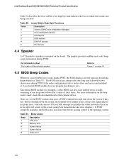
... no card installed) or if an external ROM module does not properly checksum to initialize the video and writes the error in the upper left corner of the high byte and indicates the bus on page 14 4.5 BIOS Beep Codes Whenever a recoverable error occurs during POST, the BIOS displays an error message describing the problem (see Table 57). For more information on the board. Beep Codes Beep 1 3 6 7 8 Description CPU error Memory error System failure System failure Video error...
... no card installed) or if an external ROM module does not properly checksum to initialize the video and writes the error in the upper left corner of the high byte and indicates the bus on page 14 4.5 BIOS Beep Codes Whenever a recoverable error occurs during POST, the BIOS displays an error message describing the problem (see Table 57). For more information on the board. Beep Codes Beep 1 3 6 7 8 Description CPU error Memory error System failure System failure Video error...
Intel Desktop Board D915GAG Specification Update
Page 12
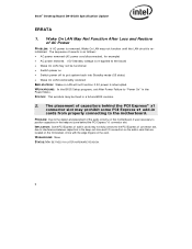
.... Intel® Desktop Board D915GAG Specification Update ERRATA 1. PROBLEM: Due to the motherboard. The sequence of the audio circuitry on this motherboard, it was necessary to position capacitors in the keep -out zone and I/O connectors on the add-in card that are located on LAN will not function if AC power is re-applied to the board • Wake On LAN may not fully connect to the PCI Express x1 connector slot, due...
.... Intel® Desktop Board D915GAG Specification Update ERRATA 1. PROBLEM: Due to the motherboard. The sequence of the audio circuitry on this motherboard, it was necessary to position capacitors in the keep -out zone and I/O connectors on the add-in card that are located on LAN will not function if AC power is re-applied to the board • Wake On LAN may not fully connect to the PCI Express x1 connector slot, due...
Simplified Chinese D915GAV Product Guide
Page 67
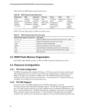
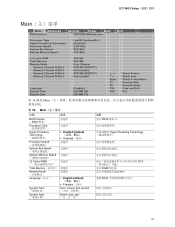
使用 BIOS Setup Main Main Advanced Security Power Boot Exit BIOS Version EV91510A.86A.xxxx.xxx Processor Type Hyper-Threading Technology Processor Speed System Bus Speed System Memory Speed Intel(R) Pentium(R) 4 [Enabled] X.XX GHz XXX MHz XXX MHz L2 Cache RAM Total Memory Memory Mode Memory Channel A Slot 0 Memory Channel A Slot 1 Memory Channel B Slot 0 Memory Channel B Slot 1 XXX KB XXX MB Dual Channel XXX MB (DDRYYY) Not Installed XXX MB (DDRYYY) Not Installed Language System Time System Date [English] [HH.MM.SS] [DD.MM.YY] Enter F1 P9 F10 ESC...
使用 BIOS Setup Main Main Advanced Security Power Boot Exit BIOS Version EV91510A.86A.xxxx.xxx Processor Type Hyper-Threading Technology Processor Speed System Bus Speed System Memory Speed Intel(R) Pentium(R) 4 [Enabled] X.XX GHz XXX MHz XXX MHz L2 Cache RAM Total Memory Memory Mode Memory Channel A Slot 0 Memory Channel A Slot 1 Memory Channel B Slot 0 Memory Channel B Slot 1 XXX KB XXX MB Dual Channel XXX MB (DDRYYY) Not Installed XXX MB (DDRYYY) Not Installed Language System Time System Date [English] [HH.MM.SS] [DD.MM.YY] Enter F1 P9 F10 ESC...

Simplified Chinese D915GAV Product Guide
Page 73
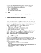
... 资源。 允许 PCI BIOS IDE 73 使用 BIOS Setup Drive Configuration Main Advanced Security Drive Configuration Power Boot Exit ATA/IDE Configuration Legacy IDE Channels PCI IDE Bus Master Hard Disk Pre-Delay [Enhanced] [PATA Pri and Sec] [Enabled] [Disabled] ` [SATA Port-0 : ` [SATA Port-1 : ` [SATA Port-2 : ` [SATA Port-3 : ` [PATA Master : ` [PATA Slave : xxxxxxx] Not Detected] xxxxxxx] xxxxxxx] Xxxxxxx] Xxxxxxx] Enter F1 P9 F10 ESC Select Screen Select Item Select ` Sub-Menu General Help Setup Defaults Save and Exit Exit 表...
... 资源。 允许 PCI BIOS IDE 73 使用 BIOS Setup Drive Configuration Main Advanced Security Drive Configuration Power Boot Exit ATA/IDE Configuration Legacy IDE Channels PCI IDE Bus Master Hard Disk Pre-Delay [Enhanced] [PATA Pri and Sec] [Enabled] [Disabled] ` [SATA Port-0 : ` [SATA Port-1 : ` [SATA Port-2 : ` [SATA Port-3 : ` [PATA Master : ` [PATA Slave : xxxxxxx] Not Detected] xxxxxxx] xxxxxxx] Xxxxxxx] Xxxxxxx] Enter F1 P9 F10 ESC Select Screen Select Item Select ` Sub-Menu General Help Setup Defaults Save and Exit Exit 表...
Simplified Chinese D915GAV Product Guide
Page 84
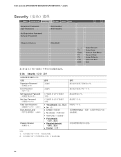
Intel D915GEV/D915GUX/D915GAV/D915GAG Security Main Advanced Security Power Boot Exit Supervisor Password : User Password : Not Installed Not Installed Set Supervisor Password Set User Password Chassis Intrusion [Disabled] Enter F1 P9 F10 ESC Select Screen Select Item Select ` Sub-Menu General Help Setup Defaults Save and Exit Exit 表 30 表 30. Security 功能 选项 说明 Supervisor Password 无选项 User Password 无选项 Set Supervisor Password Set User ...
Intel D915GEV/D915GUX/D915GAV/D915GAG Security Main Advanced Security Power Boot Exit Supervisor Password : User Password : Not Installed Not Installed Set Supervisor Password Set User Password Chassis Intrusion [Disabled] Enter F1 P9 F10 ESC Select Screen Select Item Select ` Sub-Menu General Help Setup Defaults Save and Exit Exit 表 30 表 30. Security 功能 选项 说明 Supervisor Password 无选项 User Password 无选项 Set Supervisor Password Set User ...


