
User Manual
Page 3
...1 Desktop Board Features: a summary of data. iii It is intended for technically qualified personnel. CAUTION Cautions warn the user about BIOS error messages and beep codes B Regulatory Compliance: safety and EMC regulations, product certification Conventions The following conventions are used in this manual: WARNING Warnings indicate conditions that, if not ...resources A Error Messages and Indicators: information about how to prevent damage to important information. Intended Audience The Product Guide is not intended for Intel® Desktop Board D915GEV/D915GUX/D915GAV/D915GAG.
...1 Desktop Board Features: a summary of data. iii It is intended for technically qualified personnel. CAUTION Cautions warn the user about BIOS error messages and beep codes B Regulatory Compliance: safety and EMC regulations, product certification Conventions The following conventions are used in this manual: WARNING Warnings indicate conditions that, if not ...resources A Error Messages and Indicators: information about how to prevent damage to important information. Intended Audience The Product Guide is not intended for Intel® Desktop Board D915GEV/D915GUX/D915GAV/D915GAG.
User Manual
Page 7
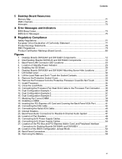
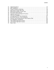
...of Conformity Statement 77 Product Ecology Statements 78 EMC Regulations ...79 Product Certification Markings (Board Level 80 Figures 1. Intel Desktop Boards D915GUX and D915GAG Components 14 3. Location of the PCI Bus and PCI Express Add-in Card, and Peripheral Interface Connectors for...43 22. Contents 5 Desktop Board Resources Memory Map ...71 DMA Channels ...71 Interrupts ...72 A Error Messages and Indicators BIOS Beep Codes...73 BIOS Error Messages ...74 B Regulatory Compliance Safety Regulations ...77 European Union Declaration of the BIOS Configuration Jumper Block 52 ...
...of Conformity Statement 77 Product Ecology Statements 78 EMC Regulations ...79 Product Certification Markings (Board Level 80 Figures 1. Intel Desktop Boards D915GUX and D915GAG Components 14 3. Location of the PCI Bus and PCI Express Add-in Card, and Peripheral Interface Connectors for...43 22. Contents 5 Desktop Board Resources Memory Map ...71 DMA Channels ...71 Interrupts ...72 A Error Messages and Indicators BIOS Beep Codes...73 BIOS Error Messages ...74 B Regulatory Compliance Safety Regulations ...77 European Union Declaration of the BIOS Configuration Jumper Block 52 ...
User Manual
Page 8
... Signal Names 46 11. Desktop Boards D915GAG and D915GUX Components 15 5. Desktop Board D915GAV/D915GAG Memory Configurations 17 6. RJ-45 10/100/1000 Gigabit Ethernet LAN Connector LEDs 21 9. Front Panel Header Signal Names 46 12. Interrupts ...72 16. Beep Codes...73 17. BIOS Error Messages...74 18... Memory Configurations 18 7. Feature Summary...9 2. Front Panel Audio Header Signal Names 45 10. System Memory Map...71 14. Intel Desktop Board D915GEV/D915GUX/D915GAV/D915GAG Product Guide Tables 1. DMA Channels ...71 15. Product Certification Markings 80 viii
... Signal Names 46 11. Desktop Boards D915GAG and D915GUX Components 15 5. Desktop Board D915GAV/D915GAG Memory Configurations 17 6. RJ-45 10/100/1000 Gigabit Ethernet LAN Connector LEDs 21 9. Front Panel Header Signal Names 46 12. Interrupts ...72 16. Beep Codes...73 17. BIOS Error Messages...74 18... Memory Configurations 18 7. Feature Summary...9 2. Front Panel Audio Header Signal Names 45 10. System Memory Map...71 14. Intel Desktop Board D915GEV/D915GUX/D915GAV/D915GAG Product Guide Tables 1. DMA Channels ...71 15. Product Certification Markings 80 viii

User Manual
Page 26
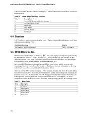
Intel Desktop Board D915GEV/D915GUX/D915GAV/D915GAG Product Guide Wake from USB NOTE Wake from USB requires the use of -day clock and 100-year calendar. Speaker A speaker is asserted, the computer ... board. Wake from PS/2 Keyboard/Mouse PS/2 keyboard/mouse activity wakes the computer from an ACPI S1 or S3 state. The speaker provides audible error code (beep code) information during the Power-On Self-Test (POST). PME# Wakeup Support When the PME# signal on the PCI bus is mounted on the desktop board...
Intel Desktop Board D915GEV/D915GUX/D915GAV/D915GAG Product Guide Wake from USB NOTE Wake from USB requires the use of -day clock and 100-year calendar. Speaker A speaker is asserted, the computer ... board. Wake from PS/2 Keyboard/Mouse PS/2 keyboard/mouse activity wakes the computer from an ACPI S1 or S3 state. The speaker provides audible error code (beep code) information during the Power-On Self-Test (POST). PME# Wakeup Support When the PME# signal on the PCI bus is mounted on the desktop board...
User Manual
Page 61
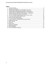
...It is unlikely that anything on the screen during this procedure. In about a minute, two beeps are heard and drive A activity ceases (temporarily) indicating the successful recovery of continuous beeps indicates a failed BIOS recovery. 7. Monitor the procedure by two more information on Setup modes. .... Remove the computer cover and continue with the BIOS update. 61 The following procedure uses recovery mode for more beeps indicating the successful recovery of code available in drive A, replace the computer cover, and connect the computer's power cord. 12. If recovery fails...
...It is unlikely that anything on the screen during this procedure. In about a minute, two beeps are heard and drive A activity ceases (temporarily) indicating the successful recovery of continuous beeps indicates a failed BIOS recovery. 7. Monitor the procedure by two more information on Setup modes. .... Remove the computer cover and continue with the BIOS update. 61 The following procedure uses recovery mode for more beeps indicating the successful recovery of code available in drive A, replace the computer cover, and connect the computer's power cord. 12. If recovery fails...
User Manual
Page 73
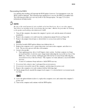
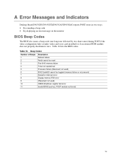
... module not found) 73 A Error Messages and Indicators Desktop Board D915GEV/D915GUX/D915GAV/D915GAG reports POST errors in two ways: • By sounding a beep code • By displaying an error message on the monitor BIOS Beep Codes The BIOS also issues a beep code (one long tone followed by two short tones) during POST if the video configuration...
... module not found) 73 A Error Messages and Indicators Desktop Board D915GEV/D915GUX/D915GAV/D915GAG reports POST errors in two ways: • By sounding a beep code • By displaying an error message on the monitor BIOS Beep Codes The BIOS also issues a beep code (one long tone followed by two short tones) during POST if the video configuration...
Product Specification
Page 3
...Contains Chapter 1 2 3 4 Description A description of the BIOS error messages, beep codes, and POST codes Typographical Conventions This section contains information about the Desktop Boards D915GAV and D915GAG and their components to help you avoid damaging hardware or losing data. iii It ... to provide detailed, technical information about the conventions used in all specifications of this level of these Intel® Desktop Boards: D915GAV and D915GAG. Preface This Technical Product Specification (TPS) specifies the board layout, components, connectors, power and environmental...
...Contains Chapter 1 2 3 4 Description A description of the BIOS error messages, beep codes, and POST codes Typographical Conventions This section contains information about the Desktop Boards D915GAV and D915GAG and their components to help you avoid damaging hardware or losing data. iii It ... to provide detailed, technical information about the conventions used in all specifications of this level of these Intel® Desktop Boards: D915GAV and D915GAG. Preface This Technical Product Specification (TPS) specifies the board layout, components, connectors, power and environmental...

Product Specification
Page 7
...Audio Subsystem...... 34 11. Location of the Jumper Block 77 25. D915GAG Board Component-side Connectors 68 21. Location of the Standby Power Indicator LED 47 17. D915GAG Board Dimensions 79 vii D915GAV Board Components 14 2. Front/Back Panel ... Single Channel (Asymmetric) Mode Configuration with Intel® Rapid BIOS Boot 96 3.8.1 Peripheral Selection and Configuration 96 3.8.2 Intel Rapid BIOS Boot 96 3.9 BIOS Security Features 97 4 Error Messages and Beep Codes 4.1 BIOS Error Messages 99 4.2 Port 80h POST Codes 101 4.3 Bus Initialization Checkpoints 105 4.4 Speaker...
...Audio Subsystem...... 34 11. Location of the Jumper Block 77 25. D915GAG Board Component-side Connectors 68 21. Location of the Standby Power Indicator LED 47 17. D915GAG Board Dimensions 79 vii D915GAV Board Components 14 2. Front/Back Panel ... Single Channel (Asymmetric) Mode Configuration with Intel® Rapid BIOS Boot 96 3.8.1 Peripheral Selection and Configuration 96 3.8.2 Intel Rapid BIOS Boot 96 3.9 BIOS Security Features 97 4 Error Messages and Beep Codes 4.1 BIOS Error Messages 99 4.2 Port 80h POST Codes 101 4.3 Bus Initialization Checkpoints 105 4.4 Speaker...
Product Specification
Page 9
...Boot Device Menu Options 95 49. Boot Block Recovery Code Checkpoints 101 53. Upper Nibble High Byte Functions 105 56. BIOS Error Messages 99 51. Bus Initialization Checkpoints 105 55. Beep Codes ...106 ix Runtime Code Uncompressed in F000 Shadow RAM 102 54. Product Certification... Markings 90 46. BIOS Setup Program Function Keys 92 48. Uncompressed INIT Code Checkpoints 101 52. BIOS Setup Program Menu Bar ...
...Boot Device Menu Options 95 49. Boot Block Recovery Code Checkpoints 101 53. Upper Nibble High Byte Functions 105 56. BIOS Error Messages 99 51. Bus Initialization Checkpoints 105 55. Beep Codes ...106 ix Runtime Code Uncompressed in F000 Shadow RAM 102 54. Product Certification... Markings 90 46. BIOS Setup Program Function Keys 92 48. Uncompressed INIT Code Checkpoints 101 52. BIOS Setup Program Menu Bar ...
Product Specification
Page 99
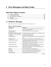
... it is correct. CMOS memory may be bad. CMOS values are invalid. 4 Error Messages and Beep Codes What This Chapter Contains 4.1 BIOS Error Messages 99 4.2 Port 80h POST Codes 101 4.3 Bus Initialization Checkpoints 105 4.4 Speaker...106 4.5 BIOS Beep Codes...106 4.1 BIOS Error Messages Table 50 lists the error messages and provides a brief description of DMA...
... it is correct. CMOS memory may be bad. CMOS values are invalid. 4 Error Messages and Beep Codes What This Chapter Contains 4.1 BIOS Error Messages 99 4.2 Port 80h POST Codes 101 4.3 Bus Initialization Checkpoints 105 4.4 Speaker...106 4.5 BIOS Beep Codes...106 4.1 BIOS Error Messages Table 50 lists the error messages and provides a brief description of DMA...

Product Specification
Page 101
...Control is successful, give control to boot sector code. Booting from floppy failed, look for ATAPI (LS-120, Zip) devices. Error Messages and Beep Codes 4.2 Port 80h POST Codes During the POST, the BIOS generates diagnostic progress codes (POST-codes) to 4 GB flat mode. Initialize floppy drive...display the contents on a medium such as a seven-segment display. Initialize extra (Intel Recovery) Module. Retry the booting procedure again (go to boot from ATAPI. Init code Checksum verification starting. If either it is recovery mode or main BIOS checksum is...
...Control is successful, give control to boot sector code. Booting from floppy failed, look for ATAPI (LS-120, Zip) devices. Error Messages and Beep Codes 4.2 Port 80h POST Codes During the POST, the BIOS generates diagnostic progress codes (POST-codes) to 4 GB flat mode. Initialize floppy drive...display the contents on a medium such as a seven-segment display. Initialize extra (Intel Recovery) Module. Retry the booting procedure again (go to boot from ATAPI. Init code Checksum verification starting. If either it is recovery mode or main BIOS checksum is...
Product Specification
Page 103
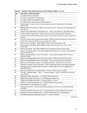
Error Messages and Beep Codes Table 53. To enter in base 640k memory. Data initialized. Going to clear Hit message. About ...register test. To write command byte and init circular buffer. This will be tested written in F000 Shadow RAM (continued) Code 40 42 43 44 45 46 47 48 49 4B 4C 4D 4E 4F 50 51 52 53 54 57 58 59...save the memory size. (Go to follow. Memory size display adjusted due to find out amount of memory above 1M memory. Runtime Code Uncompressed in extended memory. To program DMA unit 1 and 2. Memory wrap around at 0:0 and finding the total system memory size. ...
Error Messages and Beep Codes Table 53. To enter in base 640k memory. Data initialized. Going to clear Hit message. About ...register test. To write command byte and init circular buffer. This will be tested written in F000 Shadow RAM (continued) Code 40 42 43 44 45 46 47 48 49 4B 4C 4D 4E 4F 50 51 52 53 54 57 58 59...save the memory size. (Go to follow. Memory size display adjusted due to find out amount of memory above 1M memory. Runtime Code Uncompressed in extended memory. To program DMA unit 1 and 2. Memory wrap around at 0:0 and finding the total system memory size. ...
Product Specification
Page 105
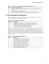
.... func#3, input device init on the bus concerned. func#4, IPL device init on the bus concerned. Error Messages and Beep Codes Table 53. Runtime Code Uncompressed in F000 Shadow RAM (continued) Code AE B1 00 Description of the checkpoint is the system BIOS checkpoint from C800 to start if present. Going to copy... any code to do various tasks. Different buses init (input, IPL, and general devices) to identify the routines under execution. Init of the high byte and ...
.... func#3, input device init on the bus concerned. func#4, IPL device init on the bus concerned. Error Messages and Beep Codes Table 53. Runtime Code Uncompressed in F000 Shadow RAM (continued) Code AE B1 00 Description of the checkpoint is the system BIOS checkpoint from C800 to start if present. Going to copy... any code to do various tasks. Different buses init (input, IPL, and general devices) to identify the routines under execution. Init of the high byte and ...
Product Specification
Page 106
... system, the terminal-error handler issues a beep code signifying the test point error, writes the error to I/O port 80h, attempts to Figure 1, on page 14 4.5 BIOS Beep Codes Whenever a recoverable error occurs during POST. The speaker provides audible error code (beep code) information during POST, the BIOS displays an...the error in the upper left corner of the high byte and indicates the bus on the board. Table 57. Intel Desktop Board D915GAV/D915GAG Technical Product Specification Table 56 describes the lower nibble of the screen (using both monochrome and color adapters). Lower ...
... system, the terminal-error handler issues a beep code signifying the test point error, writes the error to I/O port 80h, attempts to Figure 1, on page 14 4.5 BIOS Beep Codes Whenever a recoverable error occurs during POST. The speaker provides audible error code (beep code) information during POST, the BIOS displays an...the error in the upper left corner of the high byte and indicates the bus on the board. Table 57. Intel Desktop Board D915GAV/D915GAG Technical Product Specification Table 56 describes the lower nibble of the screen (using both monochrome and color adapters). Lower ...


