Product Guide
Page 4
Intel Desktop Boards D845GERG2 and D845GEBV2 Product Guide Installing a Processor 24 Installing the Processor Fan Heat Sink 24 Connecting the Processor Fan Heat Sink Cable 25 Removing the Processor 25 Installing ... Connecting Fans ...33 Connecting Power Cables 33 Setting the BIOS Configuration Jumper Block 34 Clearing Passwords ...35 Replacing the Battery ...36 3 Updating the BIOS Updating the BIOS with the Intel® Express BIOS Update Utility 39 Updating the BIOS with the Intel® Flash Memory Update Utility 40 Obtaining the BIOS Update File...
Intel Desktop Boards D845GERG2 and D845GEBV2 Product Guide Installing a Processor 24 Installing the Processor Fan Heat Sink 24 Connecting the Processor Fan Heat Sink Cable 25 Removing the Processor 25 Installing ... Connecting Fans ...33 Connecting Power Cables 33 Setting the BIOS Configuration Jumper Block 34 Clearing Passwords ...35 Replacing the Battery ...36 3 Updating the BIOS Updating the BIOS with the Intel® Express BIOS Update Utility 39 Updating the BIOS with the Intel® Flash Memory Update Utility 40 Obtaining the BIOS Update File...
Product Guide
Page 5
Desktop Board D845GEBV2 Components 10 3. Connecting the IDE Cable 29 11. Location of Standby Power Indicator 18 4. Connecting the Processor Fan Heat Sink Cable to the Processor Fan Connector ........25 8. Desktop Board D845GERG2 Components 9 2. Location of the BIOS Configuration Jumper Block 34 14. Front Panel Headers...30 12. Removing the Battery 38 v Contents Boot Menu...58 Boot...
Desktop Board D845GEBV2 Components 10 3. Connecting the IDE Cable 29 11. Location of Standby Power Indicator 18 4. Connecting the Processor Fan Heat Sink Cable to the Processor Fan Connector ........25 8. Desktop Board D845GERG2 Components 9 2. Location of the BIOS Configuration Jumper Block 34 14. Front Panel Headers...30 12. Removing the Battery 38 v Contents Boot Menu...58 Boot...
Product Guide
Page 6
... Disk Drives Submenu 59 31. Interrupts ...68 37. Beep Codes ...69 38. Intel Desktop Boards D845GERG2 and D845GEBV2 Product Guide 15. Supported Processors 11 3. Maintenance Menu ...44 12. Main Menu...45 13. Diskette Configuration Submenu 53 20. USB Configuration Submenu 54 23. Jumper Settings for the BIOS Setup Program Modes (J9H2 34 9. PCI Configuration Submenu...
... Disk Drives Submenu 59 31. Interrupts ...68 37. Beep Codes ...69 38. Intel Desktop Boards D845GERG2 and D845GEBV2 Product Guide 15. Supported Processors 11 3. Maintenance Menu ...44 12. Main Menu...45 13. Diskette Configuration Submenu 53 20. USB Configuration Submenu 54 23. Jumper Settings for the BIOS Setup Program Modes (J9H2 34 9. PCI Configuration Submenu...
Product Guide
Page 9
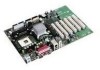
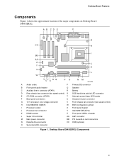
... speed control) H Intel 82845GE (GMCH) W BIOS configuration jumper I Processor socket X Front panel header J Processor fan connector Y Intel 82801DB (ICH4) K DIMM sockets Z Front panel USB 2.0 header L Super I/O controller AA AGP connector M Main power connector BB PCI bus add-in card connectors N Diskette drive connector CC CNR (optional) O Secondary IDE connector Figure 1. Desktop Board Features Components Figure...
... speed control) H Intel 82845GE (GMCH) W BIOS configuration jumper I Processor socket X Front panel header J Processor fan connector Y Intel 82801DB (ICH4) K DIMM sockets Z Front panel USB 2.0 header L Super I/O controller AA AGP connector M Main power connector BB PCI bus add-in card connectors N Diskette drive connector CC CNR (optional) O Secondary IDE connector Figure 1. Desktop Board Features Components Figure...
Product Guide
Page 10
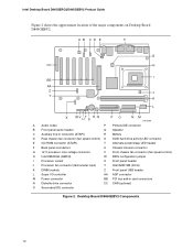
Desktop Board D845GEBV2 Components 10 Intel Desktop Board D845GERG2/D845GEBV2 Product Guide Figure 2 shows the approximate location of the major components on Desktop Board D845GEBV2. A B CD E F G CC H I BB AA Z J Y K L X WV UT S R Q PO NM OM13589 A Audio codec P ... processor core voltage connector V Front chassis fan connector (fan speed control) H Intel 82845GE (GMCH) W BIOS configuration jumper I Processor socket X Front panel header J Processor fan connector (tachometer input) Y Intel 82801DB (ICH4) K DIMM sockets Z Front panel USB header L Super I/O ...
Desktop Board D845GEBV2 Components 10 Intel Desktop Board D845GERG2/D845GEBV2 Product Guide Figure 2 shows the approximate location of the major components on Desktop Board D845GEBV2. A B CD E F G CC H I BB AA Z J Y K L X WV UT S R Q PO NM OM13589 A Audio codec P ... processor core voltage connector V Front chassis fan connector (fan speed control) H Intel 82845GE (GMCH) W BIOS configuration jumper I Processor socket X Front panel header J Processor fan connector (tachometer input) Y Intel 82801DB (ICH4) K DIMM sockets Z Front panel USB header L Super I/O ...
Product Guide
Page 21
...not available, you can result in personal injury or equipment damage. 2 Installing and Replacing Desktop Board Components This chapter tells you how to: • Install the I/O shield • Install and remove the desktop board • Install and remove a processor • Install and remove memory • ... • Install the front panel USB solution • Connect fans • Connect power cables • Set the BIOS configuration jumper • Clear passwords • Replace the battery Before You Begin WARNINGS The procedures in this chapter only at an ESD workstation using...
...not available, you can result in personal injury or equipment damage. 2 Installing and Replacing Desktop Board Components This chapter tells you how to: • Install the I/O shield • Install and remove the desktop board • Install and remove a processor • Install and remove memory • ... • Install the front panel USB solution • Connect fans • Connect power cables • Set the BIOS configuration jumper • Clear passwords • Replace the battery Before You Begin WARNINGS The procedures in this chapter only at an ESD workstation using...
Product Guide
Page 31
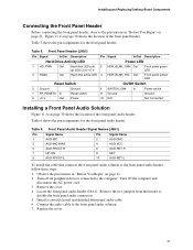
... assignments for the front panel audio header. Table 5. Remove the cover. 4. Locate the front panel audio header (J8A1). Remove the two jumpers from the header to the front panel audio header, follow these steps: 1. Figure 11 C on page 30 shows the location of the front... the computer and disconnect the AC power cord. 3. Install a correctly keyed and shielded front panel audio cable. 6. Installing and Replacing Desktop Board Components Connecting the Front Panel Header Before connecting the front panel header, observe the precautions in "Before You Begin" on page 21. Replace...
... assignments for the front panel audio header. Table 5. Remove the cover. 4. Locate the front panel audio header (J8A1). Remove the two jumpers from the header to the front panel audio header, follow these steps: 1. Figure 11 C on page 30 shows the location of the front... the computer and disconnect the AC power cord. 3. Install a correctly keyed and shielded front panel audio cable. 6. Installing and Replacing Desktop Board Components Connecting the Front Panel Header Before connecting the front panel header, observe the precautions in "Before You Begin" on page 21. Replace...

Product Guide
Page 32
... USB_FPP1USB_FPP1+ Ground USB_FP_OC0 32 Observe the precautions in "Before You Begin" on pins 5-6 (rear R channel). 6. Remove the front panel audio cable. 5. Install a jumper on page 21. 2. Table 7 shows the pin assignments for the front panel USB 2.0 header. Turn off all peripheral devices connected to the computer. Remove the... 8 9 Key 10 Note: USB ports may be assigned as needed. Figure 11 B on page 30 shows the location of the front panel USB 2.0 header. Intel Desktop Board D845GERG2/D845GEBV2 Product Guide To restore back panel operations, follow these steps: 1.
... USB_FPP1USB_FPP1+ Ground USB_FP_OC0 32 Observe the precautions in "Before You Begin" on pins 5-6 (rear R channel). 6. Remove the front panel audio cable. 5. Install a jumper on page 21. 2. Table 7 shows the pin assignments for the front panel USB 2.0 header. Turn off all peripheral devices connected to the computer. Remove the... 8 9 Key 10 Note: USB ports may be assigned as needed. Figure 11 B on page 30 shows the location of the front panel USB 2.0 header. Intel Desktop Board D845GERG2/D845GEBV2 Product Guide To restore back panel operations, follow these steps: 1.
Product Guide
Page 34
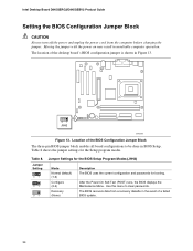
Intel Desktop Board D845GERG2/D845GEBV2 Product Guide Setting the BIOS Configuration Jumper Block CAUTION Always turn off the power and unplug the power cord from a recovery diskette in the event of the desktop board's BIOS configuration jumper is shown in Figure 13. 31 J9H2 OM13609 Figure 13. After the Power-On... Self-Test (POST) runs, the BIOS displays the Maintenance Menu. Jumper Setting 31 31 31 Jumper Settings for the BIOS Setup Program...
Intel Desktop Board D845GERG2/D845GEBV2 Product Guide Setting the BIOS Configuration Jumper Block CAUTION Always turn off the power and unplug the power cord from a recovery diskette in the event of the desktop board's BIOS configuration jumper is shown in Figure 13. 31 J9H2 OM13609 Figure 13. After the Power-On... Self-Test (POST) runs, the BIOS displays the Maintenance Menu. Jumper Setting 31 31 31 Jumper Settings for the BIOS Setup Program...
Product Guide
Page 35
... the maintenance menu. 8. Place the jumper on the computer. 35 Use the arrow keys to save the current values and exit Setup. 10. Turn off the computer. Press and Setup displays a pop-up screen requesting that the board is set to the computer. Installing and Replacing Desktop Board Components Clearing Passwords This procedure assumes...
... the maintenance menu. 8. Place the jumper on the computer. 35 Use the arrow keys to save the current values and exit Setup. 10. Turn off the computer. Press and Setup displays a pop-up screen requesting that the board is set to the computer. Installing and Replacing Desktop Board Components Clearing Passwords This procedure assumes...
Product Guide
Page 41
...of the boot block. however, if an interruption occurs, the BIOS could be damaged. Remove the computer cover and locate the configuration jumper block (see anything will not see Figure 13). 3. Turn on the screen during this procedure. The following procedure uses recovery mode...successful BIOS recovery. • A series of the BIOS core. Insert the bootable BIOS update diskette into diskette drive A. 5. On the jumper block, reinstall the jumper back on pins 1-2 as shown below to boot. Replace the computer cover, connect the power cord, turn off the computer, disconnect the...
...of the boot block. however, if an interruption occurs, the BIOS could be damaged. Remove the computer cover and locate the configuration jumper block (see anything will not see Figure 13). 3. Turn on the screen during this procedure. The following procedure uses recovery mode...successful BIOS recovery. • A series of the BIOS core. Insert the bootable BIOS update diskette into diskette drive A. 5. On the jumper block, reinstall the jumper back on pins 1-2 as shown below to boot. Replace the computer cover, connect the power cord, turn off the computer, disconnect the...

Product Guide
Page 71
...memory. BIOS Error Messages (continued) Error Message Memory Size Decreased Memory Size Increased Memory Size Changed No Boot Device Available Off Board Parity Error On Board Parity Error Parity Error NVRAM / CMOS / PASSWORD cleared by an address. A parity error occurred on an offboard card. This... error is followed by Jumper Pressed Explanation Memory size has decreased since the last boot. The system should be bad. CMOS is ...
...memory. BIOS Error Messages (continued) Error Message Memory Size Decreased Memory Size Increased Memory Size Changed No Boot Device Available Off Board Parity Error On Board Parity Error Parity Error NVRAM / CMOS / PASSWORD cleared by an address. A parity error occurred on an offboard card. This... error is followed by Jumper Pressed Explanation Memory size has decreased since the last boot. The system should be bad. CMOS is ...


