Product Guide
Page 4
... Panel Header 31 Installing a Front Panel Audio Solution 31 Installing a Front Panel USB Solution 32 Connecting Fans and Power Cables 33 Connecting Fans ...33 Connecting Power Cables 33 Setting the BIOS Configuration Jumper Block 34 Clearing Passwords ...35 Replacing the Battery ...36 3 Updating the BIOS Updating the BIOS with the Intel® Express BIOS Update Utility 39 Updating the BIOS with the Intel® Flash Memory Update Utility 40 Obtaining the BIOS Update File 40 Updating the BIOS...40 Recovering the BIOS 41 4 Using the BIOS Setup Program Maintenance Menu...44 Main Menu...
... Panel Header 31 Installing a Front Panel Audio Solution 31 Installing a Front Panel USB Solution 32 Connecting Fans and Power Cables 33 Connecting Fans ...33 Connecting Power Cables 33 Setting the BIOS Configuration Jumper Block 34 Clearing Passwords ...35 Replacing the Battery ...36 3 Updating the BIOS Updating the BIOS with the Intel® Express BIOS Update Utility 39 Updating the BIOS with the Intel® Flash Memory Update Utility 40 Obtaining the BIOS Update File 40 Updating the BIOS...40 Recovering the BIOS 41 4 Using the BIOS Setup Program Maintenance Menu...44 Main Menu...
Product Guide
Page 5
... BIOS Configuration Jumper Block 34 14. Location of Standby Power Indicator 18 4. Connecting the IDE Cable 29 11. Connecting the Processor Fan Heat Sink Cable to the Processor Fan Connector ........25 8. Contents Boot Menu...58 Boot Device Priority Submenu 59 Hard Disk Drives Submenu 59 Removable Devices Submenu 60 ATAPI CD-ROM Drives 60 Exit Menu ...61 5 Technical Reference Board Connectors ...63 Back Panel Connectors 64 Audio Connectors ...65 Add-In Card and Peripheral Interface Connectors 66 Desktop Board Resources 67 Memory Map ...67 DMA Channels ...67 Interrupts ...68 A Error...
... BIOS Configuration Jumper Block 34 14. Location of Standby Power Indicator 18 4. Connecting the IDE Cable 29 11. Connecting the Processor Fan Heat Sink Cable to the Processor Fan Connector ........25 8. Contents Boot Menu...58 Boot Device Priority Submenu 59 Hard Disk Drives Submenu 59 Removable Devices Submenu 60 ATAPI CD-ROM Drives 60 Exit Menu ...61 5 Technical Reference Board Connectors ...63 Back Panel Connectors 64 Audio Connectors ...65 Add-In Card and Peripheral Interface Connectors 66 Desktop Board Resources 67 Memory Map ...67 DMA Channels ...67 Interrupts ...68 A Error...
Product Guide
Page 6
... 8. Diskette Configuration Submenu 53 20. Hard Disk Drives Submenu 59 31. Back Panel Connectors 64 16. RJ-45 10/100/1000 Gigabit Ethernet LAN Connector LEDs 15 5. Beep Codes ...69 38. ACPI Submenu ...57 28. Jumper Settings for the BIOS Setup Program Modes (J9H2 34 9. IDE Configuration Submenu 51 18. Supported Processors 11 3. Front Panel Header (J9G1 31 6. Advanced Menu...46 14. Hardware Management 56 25. Video Configuration Submenu 54 22. Power Menu...57 27. ATAPI CD-ROM Drives Submenu...
... 8. Diskette Configuration Submenu 53 20. Hard Disk Drives Submenu 59 31. Back Panel Connectors 64 16. RJ-45 10/100/1000 Gigabit Ethernet LAN Connector LEDs 15 5. Beep Codes ...69 38. ACPI Submenu ...57 28. Jumper Settings for the BIOS Setup Program Modes (J9H2 34 9. IDE Configuration Submenu 51 18. Supported Processors 11 3. Front Panel Header (J9G1 31 6. Advanced Menu...46 14. Hardware Management 56 25. Video Configuration Submenu 54 22. Power Menu...57 27. ATAPI CD-ROM Drives Submenu...
Product Guide
Page 8
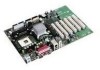
...port • One serial port • PS/2† keyboard and mouse ports Expansion Capabilities • Desktop Board D845GERG2: - Six PCI bus add-in card connectors - One AGP connector One optional CNR connector (slot shared with PCI bus connector 6) BIOS • Intel/AMI BIOS • 4 Mbit symmetrical flash memory • Support for SMBIOS Power Management • Support for Advanced Configuration and Power Interface (ACPI) • Suspend to RAM (STR) support • Wake on USB, PCI, CNR, RS-232, PS/2, LAN, and front panel Hardware Management Hardware monitor...
...port • One serial port • PS/2† keyboard and mouse ports Expansion Capabilities • Desktop Board D845GERG2: - Six PCI bus add-in card connectors - One AGP connector One optional CNR connector (slot shared with PCI bus connector 6) BIOS • Intel/AMI BIOS • 4 Mbit symmetrical flash memory • Support for SMBIOS Power Management • Support for Advanced Configuration and Power Interface (ACPI) • Suspend to RAM (STR) support • Wake on USB, PCI, CNR, RS-232, PS/2, LAN, and front panel Hardware Management Hardware monitor...
Product Guide
Page 11
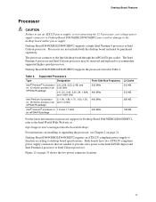
... board and must be removed and replaced to accommodate supported higher speed processors. Desktop Board D845GERG2/D845GEBV2 supports a single Intel Pentium 4 processor or Intel Celeron processor. Desktop Board Features Processor CAUTION Failure to use an ATX12V power supply, or not connecting the 12 V processor core voltage power supply connector to Desktop Board D845GERG2/D845GEBV2 may be purchased separately. Table 2. Desktop Board D845GERG2/D845GEBV2 requires an ATX12V compliant power supply to function according to the Intel desktop board through the mPGA478-pin socket...
... board and must be removed and replaced to accommodate supported higher speed processors. Desktop Board D845GERG2/D845GEBV2 supports a single Intel Pentium 4 processor or Intel Celeron processor. Desktop Board Features Processor CAUTION Failure to use an ATX12V power supply, or not connecting the 12 V processor core voltage power supply connector to Desktop Board D845GERG2/D845GEBV2 may be purchased separately. Table 2. Desktop Board D845GERG2/D845GEBV2 requires an ATX12V compliant power supply to function according to the Intel desktop board through the mPGA478-pin socket...

Product Guide
Page 12
... information about installing memory, see Chapter 2 starting on page 21. Intel Desktop Board D845GERG2/D845GEBV2 Product Guide Main Memory ✏ NOTE To be fully compliant with all applicable Intel® SDRAM memory specifications, the board should be populated with the PC SDRAM specifications. Supported memory configuration are: - DDR333 memory will attempt to 2 GB, but this effect on these documents through the World Wide Web at DDR266 speeds when using a processor with 533...
... information about installing memory, see Chapter 2 starting on page 21. Intel Desktop Board D845GERG2/D845GEBV2 Product Guide Main Memory ✏ NOTE To be fully compliant with all applicable Intel® SDRAM memory specifications, the board should be populated with the PC SDRAM specifications. Supported memory configuration are: - DDR333 memory will attempt to 2 GB, but this effect on these documents through the World Wide Web at DDR266 speeds when using a processor with 533...
Product Guide
Page 14
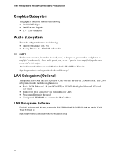
.../support/motherboards/desktop 14 Audio drivers and utilities are connected to power either headphones or amplified speakers only. Poor audio quality may occur if passive (non-amplified) speakers are available from Intel's World Wide Web site: http://support.intel.com/support/motherboards/desktop/ LAN Subsystem (Optional) The optional LAN (with status indicator LEDs • Programmable transit threshold • Configurable EEPROM that contains the MAC address LAN Subsystem Software For LAN software and drivers, refer to the D845GERG2 or D845GEBV2...
.../support/motherboards/desktop 14 Audio drivers and utilities are connected to power either headphones or amplified speakers only. Poor audio quality may occur if passive (non-amplified) speakers are available from Intel's World Wide Web site: http://support.intel.com/support/motherboards/desktop/ LAN Subsystem (Optional) The optional LAN (with status indicator LEDs • Programmable transit threshold • Configurable EEPROM that contains the MAC address LAN Subsystem Software For LAN software and drivers, refer to the D845GERG2 or D845GEBV2...
Product Guide
Page 17
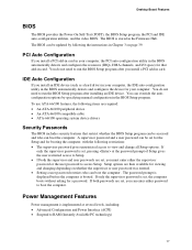
... card. If only the supervisor password is set, pressing at several levels, including: • Advanced Configuration and Power Interface (ACPI) • Suspend to access Setup. The BIOS can boot the computer. PCI Auto Configuration If you can boot the computer. The password prompt is displayed before the computer is implemented at the password prompt of Setup gives the user restricted access to run the BIOS Setup program after you install an IDE device (such as a hard drive...
... card. If only the supervisor password is set, pressing at several levels, including: • Advanced Configuration and Power Interface (ACPI) • Suspend to access Setup. The BIOS can boot the computer. PCI Auto Configuration If you can boot the computer. The password prompt is displayed before the computer is implemented at the password prompt of Setup gives the user restricted access to run the BIOS Setup program after you install an IDE device (such as a hard drive...
Product Guide
Page 27
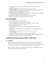
... AC power cord. Replace the computer's cover and reconnect the AC power cord. Reinstall and reconnect any AGP or ADD card in the AGP connector, an electrical short may be damaged. If the card is not fully seated in the desktop board, ensure that it was removed prior to the computer. The DIMM pops out of the DIMM socket. Installing and Replacing Desktop Board Components...
... AC power cord. Replace the computer's cover and reconnect the AC power cord. Reinstall and reconnect any AGP or ADD card in the AGP connector, an electrical short may be damaged. If the card is not fully seated in the desktop board, ensure that it was removed prior to the computer. The DIMM pops out of the DIMM socket. Installing and Replacing Desktop Board Components...
Product Guide
Page 31
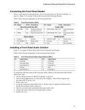
... keyed and shielded front panel audio cable. 6. Figure 11 C on page 30 shows the location of the front panel header. Remove the cover. 4. Table 5 shows the pin assignments for the front panel audio header. Table 6 shows the pin assignments for the front panel header. Observe the precautions in "Before You Begin" on page 21. 2. Connect the audio cable to disable the back panel audio connectors. 5. Installing and Replacing Desktop Board Components Connecting the Front Panel Header Before connecting the front panel header...
... keyed and shielded front panel audio cable. 6. Figure 11 C on page 30 shows the location of the front panel header. Remove the cover. 4. Table 5 shows the pin assignments for the front panel audio header. Table 6 shows the pin assignments for the front panel header. Observe the precautions in "Before You Begin" on page 21. 2. Connect the audio cable to disable the back panel audio connectors. 5. Installing and Replacing Desktop Board Components Connecting the Front Panel Header Before connecting the front panel header...
Product Guide
Page 34
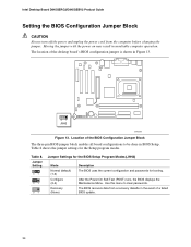
..., the BIOS displays the Maintenance Menu. The BIOS recovers data from the computer before changing the jumper. Table 8. The location of the BIOS Configuration Jumper Block The three-pin BIOS jumper block enables all board configurations to clear passwords. Jumper Setting 31 31 31 Jumper Settings for the BIOS Setup Program Modes (J9H2) Mode Normal (default) (1-2) Configure (2-3) Recovery (None) Description The BIOS uses the current configuration and passwords for the Setup program modes. Use this menu to be done in BIOS Setup. Intel Desktop Board D845GERG2/D845GEBV2 Product Guide...
..., the BIOS displays the Maintenance Menu. The BIOS recovers data from the computer before changing the jumper. Table 8. The location of the BIOS Configuration Jumper Block The three-pin BIOS jumper block enables all board configurations to clear passwords. Jumper Setting 31 31 31 Jumper Settings for the BIOS Setup Program Modes (J9H2) Mode Normal (default) (1-2) Configure (2-3) Recovery (None) Description The BIOS uses the current configuration and passwords for the Setup program modes. Use this menu to be done in BIOS Setup. Intel Desktop Board D845GERG2/D845GEBV2 Product Guide...
Product Guide
Page 35
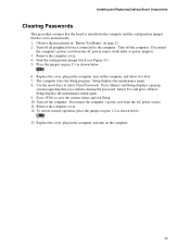
... the AC power source. 11. Remove the computer cover. 4. Replace the cover, plug in the computer and the configuration jumper block is set to the computer. Disconnect the computer's power cord from the AC power source (wall outlet or power adapter). 3. Turn off all peripheral devices connected to normal mode. 1. The computer starts the Setup program. Press and Setup displays a pop-up screen requesting that the board is installed in the...
... the AC power source. 11. Remove the computer cover. 4. Replace the cover, plug in the computer and the configuration jumper block is set to the computer. Disconnect the computer's power cord from the AC power source (wall outlet or power adapter). 3. Turn off all peripheral devices connected to normal mode. 1. The computer starts the Setup program. Press and Setup displays a pop-up screen requesting that the board is installed in the...
Product Guide
Page 43
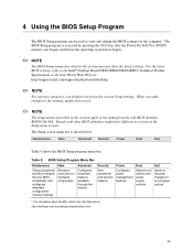
... Setup screen menu bar is accessed by pressing the key after the Power-On Self-Test (POST) memory test begins and before the operating system boot begins. ✏ NOTE The BIOS Setup menus described in this section apply to the Intel® Desktop Board D845GERG2/D845GEBV2 Technical Product Specification or the Intel World Wide Web site: http://support.intel.com/support/motherboards/desktop ✏ NOTE For reference purposes, you make changes to the settings, update...
... Setup screen menu bar is accessed by pressing the key after the Power-On Self-Test (POST) memory test begins and before the operating system boot begins. ✏ NOTE The BIOS Setup menus described in this section apply to the Intel® Desktop Board D845GERG2/D845GEBV2 Technical Product Specification or the Intel World Wide Web site: http://support.intel.com/support/motherboards/desktop ✏ NOTE For reference purposes, you make changes to the settings, update...
Product Guide
Page 51
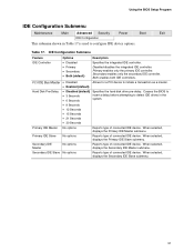
... of connected IDE device. PCI IDE Bus Master • Disabled Allows for a PCI device to configure IDE device options. Primary IDE Slave No options Reports type of connected IDE device. Secondary IDE Slave No options Reports type of connected IDE device. Table 17. Both enables both IDE controllers. When selected, displays the Primary IDE Slave submenu. When selected, displays the Secondary IDE Slave submenu. 51 When selected, displays the Secondary IDE Master submenu. Using the BIOS Setup Program IDE Configuration Submenu Maintenance Main Advanced Security Power Boot...
... of connected IDE device. PCI IDE Bus Master • Disabled Allows for a PCI device to configure IDE device options. Primary IDE Slave No options Reports type of connected IDE device. Secondary IDE Slave No options Reports type of connected IDE device. Table 17. Both enables both IDE controllers. When selected, displays the Primary IDE Slave submenu. When selected, displays the Secondary IDE Slave submenu. 51 When selected, displays the Secondary IDE Master submenu. Using the BIOS Setup Program IDE Configuration Submenu Maintenance Main Advanced Security Power Boot...
Product Guide
Page 52
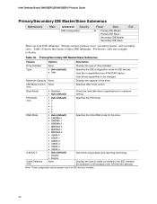
Intel Desktop Board D845GERG2/D845GEBV2 Product Guide Primary/Secondary IDE Master/Slave Submenus Maintenance Main Advanced Security Power Boot Exit IDE Configuration ➜ Primary IDE Master Primary IDE Slave Secondary IDE Master Secondary IDE Slave There are four IDE submenus: Primary master, primary slave, secondary master, and secondary slave. User allows capabilities to the IDE interface: 40-conductor or 80-conductor (for the drive. Block Mode • Disabled • Auto (default) Check the hard disk drive's specifications for...
Intel Desktop Board D845GERG2/D845GEBV2 Product Guide Primary/Secondary IDE Master/Slave Submenus Maintenance Main Advanced Security Power Boot Exit IDE Configuration ➜ Primary IDE Master Primary IDE Slave Secondary IDE Master Secondary IDE Slave There are four IDE submenus: Primary master, primary slave, secondary master, and secondary slave. User allows capabilities to the IDE interface: 40-conductor or 80-conductor (for the drive. Block Mode • Disabled • Auto (default) Check the hard disk drive's specifications for...
Product Guide
Page 53
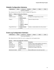
... floppy drive type. Table 20. Clear Event Log Event Logging No options • Disabled • Enabled (default) Discards all DMI events in the event log as read. 53 Using the BIOS Setup Program Diskette Configuration Submenu Maintenance Main Advanced Security Power Boot Exit Diskette Configuration This submenu shown in Table 19 is space available in the event log. Diskette Configuration Submenu Feature Diskette Controller Floppy A Floppy Write Protect Options • Disabled • Enabled (default...
... floppy drive type. Table 20. Clear Event Log Event Logging No options • Disabled • Enabled (default) Discards all DMI events in the event log as read. 53 Using the BIOS Setup Program Diskette Configuration Submenu Maintenance Main Advanced Security Power Boot Exit Diskette Configuration This submenu shown in Table 19 is space available in the event log. Diskette Configuration Submenu Feature Diskette Controller Floppy A Floppy Write Protect Options • Disabled • Enabled (default...
Product Guide
Page 54
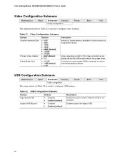
... (default) • PCI • 512 KB • 1 MB (default) • 8 MB Description Amount of system memory available for legacy USB. 54 Controls how much system RAM is not available. Intel Desktop Board D845GERG2/D845GEBV2 Product Guide Video Configuration Submenu Maintenance Main Advanced Security Power Boot Exit Video Configuration The submenu shown in Table 22 is used to configure USB features. USB Configuration Submenu Maintenance Main Advanced Security Power Boot Exit USB Configuration The menu shown in Table 21 is used to configure video features...
... (default) • PCI • 512 KB • 1 MB (default) • 8 MB Description Amount of system memory available for legacy USB. 54 Controls how much system RAM is not available. Intel Desktop Board D845GERG2/D845GEBV2 Product Guide Video Configuration Submenu Maintenance Main Advanced Security Power Boot Exit Video Configuration The submenu shown in Table 22 is used to configure USB features. USB Configuration Submenu Maintenance Main Advanced Security Power Boot Exit USB Configuration The menu shown in Table 21 is used to configure video features...
Product Guide
Page 55
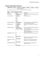
... detected memory frequency value. Aggressive • Manual - Chooses the default or user defined settings for the extended configuration options. Selects the number of time required before accessing a new row. 55 Selects the length of clock cycles required to address a column in Table 23 is used to pre-change. Set PCI latency time. Manual - User Defined SDRAM RAS Act. Manual - Using the BIOS Setup Program Chipset Configuration Submenu Maintenance Main Advanced Security Power Boot Exit Chipset Configuration The menu...
... detected memory frequency value. Aggressive • Manual - Chooses the default or user defined settings for the extended configuration options. Selects the number of time required before accessing a new row. 55 Selects the length of clock cycles required to address a column in Table 23 is used to pre-change. Set PCI latency time. Manual - User Defined SDRAM RAS Act. Manual - Using the BIOS Setup Program Chipset Configuration Submenu Maintenance Main Advanced Security Power Boot Exit Chipset Configuration The menu...
Product Guide
Page 56
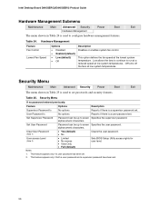
... been set . This option defines the fan speed at low system temperatures. Set User Password Password can be up to seven Specifies the supervisor password. Table 25. Notes: 1. Security Menu If no password entered previously: Feature Options Description Supervisor Password Is No options Reports if there is a supervisor password set . 56 Security Menu Maintenance Main Advanced Security Power Boot Exit The menu shown in Table 24 is used to set passwords and security features. Intel Desktop Board D845GERG2/D845GEBV2 Product Guide...
... been set . This option defines the fan speed at low system temperatures. Set User Password Password can be up to seven Specifies the supervisor password. Table 25. Notes: 1. Security Menu If no password entered previously: Feature Options Description Supervisor Password Is No options Reports if there is a supervisor password set . 56 Security Menu Maintenance Main Advanced Security Power Boot Exit The menu shown in Table 24 is used to set passwords and security features. Intel Desktop Board D845GERG2/D845GEBV2 Product Guide...

Product Guide
Page 58
... BIOS to scan the flash ROM for user binary • Enabled (default) files that are executed at boot time. • Disabled (default) Disables or enables PXE boot to LAN. • Enabled • Disabled Disables or enables booting to set the boot features and the boot sequence. No options Specifies the boot sequence from the available removable devices. No options Specifies the boot sequence from the available hard disk drives. Intel Desktop Board D845GERG2/D845GEBV2 Product Guide Boot Menu Maintenance Main Advanced Security Power Boot Exit Boot Device Priority Hard Disk...
... BIOS to scan the flash ROM for user binary • Enabled (default) files that are executed at boot time. • Disabled (default) Disables or enables PXE boot to LAN. • Enabled • Disabled Disables or enables booting to set the boot features and the boot sequence. No options Specifies the boot sequence from the available removable devices. No options Specifies the boot sequence from the available hard disk drives. Intel Desktop Board D845GERG2/D845GEBV2 Product Guide Boot Menu Maintenance Main Advanced Security Power Boot Exit Boot Device Priority Hard Disk...


