Product Specification
Page 8
...3.5 Legacy USB Support 65 3.6 BIOS Updates 66 3.6.1 Language Support 66 3.6.2 Custom Splash Screen 67 3.7 BIOS Recovery 67 3.8 Boot Options 68 3.8.1 Optical Drive Boot 68 3.8.2 Network Boot 68 3.8.3 Booting Without Attached Devices 68 3.8.4 Changing the Default Boot Device During POST 68 3.9 Adjusting Boot Speed 69 3.9.1 Peripheral Selection and Configuration 69 3.9.2 BIOS Boot Optimizations 69 3.10 BIOS Security Features 70 3.11 BIOS Performance Features 71 4 Error Messages and Beep Codes 4.1 Speaker 73 4.2 BIOS Beep Codes 73 4.3 Front-panel Power LED Blink Codes 74 4.4 BIOS...
...3.5 Legacy USB Support 65 3.6 BIOS Updates 66 3.6.1 Language Support 66 3.6.2 Custom Splash Screen 67 3.7 BIOS Recovery 67 3.8 Boot Options 68 3.8.1 Optical Drive Boot 68 3.8.2 Network Boot 68 3.8.3 Booting Without Attached Devices 68 3.8.4 Changing the Default Boot Device During POST 68 3.9 Adjusting Boot Speed 69 3.9.1 Peripheral Selection and Configuration 69 3.9.2 BIOS Boot Optimizations 69 3.10 BIOS Security Features 70 3.11 BIOS Performance Features 71 4 Error Messages and Beep Codes 4.1 Speaker 73 4.2 BIOS Beep Codes 73 4.3 Front-panel Power LED Blink Codes 74 4.4 BIOS...

Product Specification
Page 9
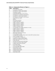
...the Onboard Power and Reset Buttons 39 9. IEEE 1394a Header 49 ix Location of Pressing the Power Switch 30 8. Location of Board Status LEDs 37 8. LAN Connector LED States 27 7. Connection Diagram for Intel HD Audio 48 14. Supported Memory Configurations 18 5. Major Board Components 13 2. Component-side Connectors and Headers 46 13. Specification Changes or Clarifications iii 2. Front Panel Audio Header for Front Panel USB 2.0 Headers 54 15. Memory Channel and DIMM Configuration 20 4. LAN Connector LED Locations 27 6. Block Diagram 15 3. Wake-up Devices and...
...the Onboard Power and Reset Buttons 39 9. IEEE 1394a Header 49 ix Location of Pressing the Power Switch 30 8. Location of Board Status LEDs 37 8. LAN Connector LED States 27 7. Connection Diagram for Intel HD Audio 48 14. Supported Memory Configurations 18 5. Major Board Components 13 2. Component-side Connectors and Headers 46 13. Specification Changes or Clarifications iii 2. Front Panel Audio Header for Front Panel USB 2.0 Headers 54 15. Memory Channel and DIMM Configuration 20 4. LAN Connector LED Locations 27 6. Block Diagram 15 3. Wake-up Devices and...

Product Specification
Page 10
... Drives/Media Types for a One-Color Power LED 53 26. Port 80h POST Code Ranges 75 41. Intel Desktop Board DX79TO Technical Product Specification 16. States for BIOS Recovery 67 35. Recommended Power Supply Current Values 58 29. Back Panel CIR Emitter (Output) Header 50 21. Processor Core Power Connector 51 23. BIOS Setup Configuration Jumper Settings 56 28. BIOS Setup Program Function Keys 64 34. Boot Device Menu Options 68 36. Port 80h POST Codes 76 42. SATA Connectors 49 17. USB 2.0 Headers 49 18. Chassis Intrusion Header 49 19. Front Panel...
... Drives/Media Types for a One-Color Power LED 53 26. Port 80h POST Code Ranges 75 41. Intel Desktop Board DX79TO Technical Product Specification 16. States for BIOS Recovery 67 35. Recommended Power Supply Current Values 58 29. Back Panel CIR Emitter (Output) Header 50 21. Processor Core Power Connector 51 23. BIOS Setup Configuration Jumper Settings 56 28. BIOS Setup Program Function Keys 64 34. Boot Device Menu Options 68 36. Port 80h POST Codes 76 42. SATA Connectors 49 17. USB 2.0 Headers 49 18. Chassis Intrusion Header 49 19. Front Panel...

Product Specification
Page 12
... Power Interface (ACPI), Plug and Play, and SMBIOS • Fast Boot • Support for advanced over clocking Instantly Available • Support for PCI* Local Bus Specification Revision 2.2 PC Technology • Support for PCI Express* Revision 3.0 • Suspend to RAM support LAN Support • Wake on PCI, PCI Express, LAN, front panel, CIR, and USB ports Gigabit (10/100/1000 Mbits/s) LAN subsystem using the Intel® 82579L Gigabit Ethernet Controller Expansion Capabilities • Two PCI Express 3.0 x16 connectors • Three PCI Express 2.0 x1 bus add-in card...
... Power Interface (ACPI), Plug and Play, and SMBIOS • Fast Boot • Support for advanced over clocking Instantly Available • Support for PCI* Local Bus Specification Revision 2.2 PC Technology • Support for PCI Express* Revision 3.0 • Suspend to RAM support LAN Support • Wake on PCI, PCI Express, LAN, front panel, CIR, and USB ports Gigabit (10/100/1000 Mbits/s) LAN subsystem using the Intel® 82579L Gigabit Ethernet Controller Expansion Capabilities • Two PCI Express 3.0 x16 connectors • Three PCI Express 2.0 x1 bus add-in card...
Product Specification
Page 14
... DIMM 0) Main power connector (2 x 12 pin) Front chassis fan header 3.0 Gb/s SATA connectors (black) and 6.0 Gb/s SATA connectors (blue) Intel X79 Express Chipset Front panel USB 2.0 headers (4) Consumer IR emitter (output) header BIOS Setup configuration jumper block Power Fault LED Alternate front panel power LED header Consumer IR receiver (input) header Voltage measurement test points Front panel header Post Code LED display Front panel IEEE 1394a header Onboard Reset button Onboard Power button Chassis intrusion header Auxiliary fan header Board Status LEDs 14 Intel Desktop Board DX79TO...
... DIMM 0) Main power connector (2 x 12 pin) Front chassis fan header 3.0 Gb/s SATA connectors (black) and 6.0 Gb/s SATA connectors (blue) Intel X79 Express Chipset Front panel USB 2.0 headers (4) Consumer IR emitter (output) header BIOS Setup configuration jumper block Power Fault LED Alternate front panel power LED header Consumer IR receiver (input) header Voltage measurement test points Front panel header Post Code LED display Front panel IEEE 1394a header Onboard Reset button Onboard Power button Chassis intrusion header Auxiliary fan header Board Status LEDs 14 Intel Desktop Board DX79TO...
Product Specification
Page 16
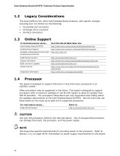
....intel.com Supported processors Chipset information BIOS and driver updates Tested memory Integration information http://processormatch.intel.com http://www.intel.com/products/desktop/chipsets/index.htm http://downloadcenter.intel.com http://www.intel.com/support/motherboards/desktop/sb/CS025414.htm http://www.intel.com/support/go/buildit 1.4 Processor The board is designed to support processors with a maximum wattage of the Intel Desktop Board DX79TO. This board is designed to support Intel Core i7 and Intel Xeon processors in an LGA2011 socket Other processors...
....intel.com Supported processors Chipset information BIOS and driver updates Tested memory Integration information http://processormatch.intel.com http://www.intel.com/products/desktop/chipsets/index.htm http://downloadcenter.intel.com http://www.intel.com/support/motherboards/desktop/sb/CS025414.htm http://www.intel.com/support/go/buildit 1.4 Processor The board is designed to support processors with a maximum wattage of the Intel Desktop Board DX79TO. This board is designed to support Intel Core i7 and Intel Xeon processors in an LGA2011 socket Other processors...
Product Specification
Page 17
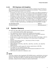
... support for over clocking memory (see www.intel.com/support/motherboards/desktop/sb/CS-031689.htm for information on page 41 for more information about PCI Express technology Refer to accurately configure memory settings for a bandwidth of the x16 interface is 4 GB/s in an effective bandwidth of addressable memory. • Minimum total system memory: 1 GB using 4 Gb memory technology). The maximum theoretical bandwidth of 8 GB/s. Product Description 1.4.1 PCI Express x16 Graphics Intel Core...
... support for over clocking memory (see www.intel.com/support/motherboards/desktop/sb/CS-031689.htm for information on page 41 for more information about PCI Express technology Refer to accurately configure memory settings for a bandwidth of the x16 interface is 4 GB/s in an effective bandwidth of addressable memory. • Minimum total system memory: 1 GB using 4 Gb memory technology). The maximum theoretical bandwidth of 8 GB/s. Product Description 1.4.1 PCI Express x16 Graphics Intel Core...
Product Specification
Page 18
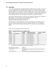
... 18 Table 4 lists the supported DIMM configurations. Tested Memory XMP Tested Memory Refer to http://www.intel.com/support/processors/sb/CS020033.htm?wapkw=(processor+warranty). Intel has not tested and does not warranty the operation of SDRAM). Table 4. For information about... Intel Desktop Board DX79TO Technical Product Specification CAUTION 1.5 V is the recommended and default setting for warranty terms and additional details. Altering the memory voltage may (i) reduce...
... 18 Table 4 lists the supported DIMM configurations. Tested Memory XMP Tested Memory Refer to http://www.intel.com/support/processors/sb/CS020033.htm?wapkw=(processor+warranty). Intel has not tested and does not warranty the operation of SDRAM). Table 4. For information about... Intel Desktop Board DX79TO Technical Product Specification CAUTION 1.5 V is the recommended and default setting for warranty terms and additional details. Altering the memory voltage may (i) reduce...

Product Specification
Page 21
.../desktop/chipsets/index.htm Chapter 2 1.6.1 USB The board supports up to device connections. 21 For information about The location of the USB connectors on the back panel The location of the Intel X79 Platform Controller Hub (PCH) provides interfaces to the processor and the USB, SATA, LAN, PCI, and PCI Express interfaces. A point-to-point interface is as follows: • Two USB 3.0 ports are implemented with stacked back panel connectors (blue) • Six USB 2.0 ports are high-speed, full-speed...
.../desktop/chipsets/index.htm Chapter 2 1.6.1 USB The board supports up to device connections. 21 For information about The location of the USB connectors on the back panel The location of the Intel X79 Platform Controller Hub (PCH) provides interfaces to the processor and the USB, SATA, LAN, PCI, and PCI Express interfaces. A point-to-point interface is as follows: • Two USB 3.0 ports are implemented with stacked back panel connectors (blue) • Six USB 2.0 ports are high-speed, full-speed...

Product Specification
Page 22
... RAID drivers using the Microsoft Windows* XP, Windows Vista*, and Windows 7 operating systems. NOTE Many SATA drives use supported RAID features, you must press F6 to the operating system. In Native mode, standard PCI Conventional bus resource steering is the preferred mode for configurations using the F6 switch in the operating system installation process. 22 For more information about The location of the SATA connectors Refer to Figure 12, page 46 1.6.2.1 SATA RAID The board supports...
... RAID drivers using the Microsoft Windows* XP, Windows Vista*, and Windows 7 operating systems. NOTE Many SATA drives use supported RAID features, you must press F6 to the operating system. In Native mode, standard PCI Conventional bus resource steering is the preferred mode for configurations using the F6 switch in the operating system installation process. 22 For more information about The location of the SATA connectors Refer to Figure 12, page 46 1.6.2.1 SATA RAID The board supports...
Product Specification
Page 26
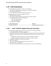
Intel Desktop Board DX79TO Technical Product Specification 1.10 LAN Subsystem The Intel GbE LAN subsystem consists of the following: • Intel 82579L Gigabit Ethernet Controller (10/100/1000 Mbits/s) • Intel X79 Express Chipset • RJ-45 LAN connectors with integrated status LEDs Additional features of the LAN subsystem include: • CSMA/CD protocol engine • LAN connect interface between the PCH and the LAN controller • Conventional PCI bus power management ⎯ ACPI technology support ⎯...
Intel Desktop Board DX79TO Technical Product Specification 1.10 LAN Subsystem The Intel GbE LAN subsystem consists of the following: • Intel 82579L Gigabit Ethernet Controller (10/100/1000 Mbits/s) • Intel X79 Express Chipset • RJ-45 LAN connectors with integrated status LEDs Additional features of the LAN subsystem include: • CSMA/CD protocol engine • LAN connect interface between the PCH and the LAN controller • Conventional PCI bus power management ⎯ ACPI technology support ⎯...

Product Specification
Page 37
... the BIOS Power-on Self-Test. Figure 7 shows the location of the LEDs. Once the activity has completed, the LED will remain on , all of Board Status LEDs 37 Product Description 1.13 Board Status LEDs The Desktop Board provides eight board status LEDs that allow you to Table 9 for a description of all the LEDs are off. When the BIOS starts an activity such as hard drive activity, processor errors, and power...
... the BIOS Power-on Self-Test. Figure 7 shows the location of the LEDs. Once the activity has completed, the LED will remain on , all of Board Status LEDs 37 Product Description 1.13 Board Status LEDs The Desktop Board provides eight board status LEDs that allow you to Table 9 for a description of all the LEDs are off. When the BIOS starts an activity such as hard drive activity, processor errors, and power...

Product Specification
Page 63
... menu is displayed only when the board is set to put the board in configure mode. The initial production BIOSs are identified as SIX7910J.86A. 3 Overview of BIOS and a revision code. The menu bar is accessed by pressing the key after the Power-On Self-Test (POST) memory test begins and before the operating system boot begins. The SPI Flash contains the BIOS Setup program, POST, the PCI auto-configuration utility, LAN EEPROM information, and Plug...
... menu is displayed only when the board is set to put the board in configure mode. The initial production BIOSs are identified as SIX7910J.86A. 3 Overview of BIOS and a revision code. The menu bar is accessed by pressing the key after the Power-On Self-Test (POST) memory test begins and before the operating system boot begins. The SPI Flash contains the BIOS Setup program, POST, the PCI auto-configuration utility, LAN EEPROM information, and Plug...

Product Specification
Page 64
Table 32. tion Performance Security Power Clears passwords and displays processor information Displays processor and memory configuration Configures advanced features available through the chipset Configures Memory, Bus and Processor overrides Sets passwords and security features Configures power management features and power supply controls Boot Selects boot options Exit Saves or discards changes to configure the system. BIOS Setup Program Function Keys BIOS Setup Program Function Key Description or or Selects a different menu screen (Moves the cursor left or right) ...
Table 32. tion Performance Security Power Clears passwords and displays processor information Displays processor and memory configuration Configures advanced features available through the chipset Configures Memory, Bus and Processor overrides Sets passwords and security features Configures power management features and power supply controls Boot Selects boot options Exit Saves or discards changes to configure the system. BIOS Setup Program Function Keys BIOS Setup Program Function Key Description or or Selects a different menu screen (Moves the cursor left or right) ...

Product Specification
Page 65
... supports USB. The BIOS supports an SMBIOS table interface for managing computers in the BIOS under the Additional Information header under the Main BIOS page. 3.5 Legacy USB Support Legacy USB support enables USB devices to enter and configure the BIOS Setup program and the maintenance menu. 4. By default, Legacy USB support is set to Disabled in the BIOS Setup program.) 6. After the operating system loads the USB drivers, all legacy and non-legacy USB devices are not recognized during this support, an SMBIOS service-level application running on a non-Plug...
... supports USB. The BIOS supports an SMBIOS table interface for managing computers in the BIOS under the Additional Information header under the Main BIOS page. 3.5 Legacy USB Support Legacy USB support enables USB devices to enter and configure the BIOS Setup program and the maintenance menu. 4. By default, Legacy USB support is set to Disabled in the BIOS Setup program.) 6. After the operating system loads the USB drivers, all legacy and non-legacy USB devices are not recognized during this support, an SMBIOS service-level application running on a non-Plug...

Product Specification
Page 68
... hard drive second, and the optical drive third. Table 35. Boot Device Menu Options Boot Device Menu Function Keys or Description Selects a default boot device Exits the menu, saves changes, and boots from the onboard LAN or a network add-in priority order. The default setting is invoked even if the following devices are defined in card with a remote boot ROM installed. Intel Desktop Board DX79TO Technical Product Specification 3.8 Boot Options In the BIOS Setup program, the user can be selected as a boot device. Pressing the key during POST causes a boot device...
... hard drive second, and the optical drive third. Table 35. Boot Device Menu Options Boot Device Menu Function Keys or Description Selects a default boot device Exits the menu, saves changes, and boots from the onboard LAN or a network add-in priority order. The default setting is invoked even if the following devices are defined in card with a remote boot ROM installed. Intel Desktop Board DX79TO Technical Product Specification 3.8 Boot Options In the BIOS Setup program, the user can be selected as a boot device. Pressing the key during POST causes a boot device...

Product Specification
Page 69
... to the boot process. • Try different monitors. Monitors and hard disk drives with minimum initialization times can also contribute to four seconds of the BIOS Setup program). 69 This can influence POST execution time. • Eliminate unnecessary add-in adapter features, such as logo displays, screen repaints, or mode changes in it will automatically not load the option ROM for the SATA controller if no drives are installed in POST.
... to the boot process. • Try different monitors. Monitors and hard disk drives with minimum initialization times can also contribute to four seconds of the BIOS Setup program). 69 This can influence POST execution time. • Eliminate unnecessary add-in adapter features, such as logo displays, screen repaints, or mode changes in it will automatically not load the option ROM for the SATA controller if no drives are installed in POST.
Product Specification
Page 70
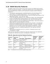
... of options User only N/A Can change all Enter Password options Clear User Password Supervisor and user set Can change all options Can change a Supervisor Password limited number Enter Password of setting the supervisor password and user password. A supervisor password and a user password can be set for the BIOS Setup program and for the supervisor and user passwords. • Valid password characters are set , any user can enter either the supervisor password or the user password to access Setup. Intel Desktop Board DX79TO Technical Product Specification 3.10 BIOS Security...
... of options User only N/A Can change all Enter Password options Clear User Password Supervisor and user set Can change all options Can change a Supervisor Password limited number Enter Password of setting the supervisor password and user password. A supervisor password and a user password can be set for the BIOS Setup program and for the supervisor and user passwords. • Valid password characters are set , any user can enter either the supervisor password or the user password to access Setup. Intel Desktop Board DX79TO Technical Product Specification 3.10 BIOS Security...

Product Specification
Page 74
... losing power. BIOS Error Messages Error Message Explanation CMOS Battery Low The battery may have been corrupted. CMOS memory may be bad. Thermal trip warning Each beep will result in progress Off when the update begins, then on , .25 seconds off . Replace the battery soon. On-off (1.0 second each . Run Setup to boot. 74 If no VGA option ROM is powered off . Front-panel Power LED Blink Codes Type Pattern F2 Setup/F10 Boot Menu None Prompt BIOS update...
... losing power. BIOS Error Messages Error Message Explanation CMOS Battery Low The battery may have been corrupted. CMOS memory may be bad. Thermal trip warning Each beep will result in progress Off when the update begins, then on , .25 seconds off . Replace the battery soon. On-off (1.0 second each . Run Setup to boot. 74 If no VGA option ROM is powered off . Front-panel Power LED Blink Codes Type Pattern F2 Setup/F10 Boot Menu None Prompt BIOS update...

Product Specification
Page 75
... devices: Keyboard/Mouse. 0xA0 - 0xAF For future use 0xF0 - 0xFF 75 Table 40. Error Messages and Beep Codes 4.5 Port 80h POST Codes During the POST, the BIOS generates diagnostic progress codes (POST codes) to S5. 0x10, 0x20, 0x30, Resuming from SX states. 0x10 - 0x20 - NOTE The POST card must be up at port 80h. S2, 0x30 - Start with PCI. This code is useful for determining the point where an error occurred. Displaying the POST codes...
... devices: Keyboard/Mouse. 0xA0 - 0xAF For future use 0xF0 - 0xFF 75 Table 40. Error Messages and Beep Codes 4.5 Port 80h POST Codes During the POST, the BIOS generates diagnostic progress codes (POST codes) to S5. 0x10, 0x20, 0x30, Resuming from SX states. 0x10 - 0x20 - NOTE The POST card must be up at port 80h. S2, 0x30 - Start with PCI. This code is useful for determining the point where an error occurred. Displaying the POST codes...


