Product Guide
Page 3
... BIOS: instructions on how to update the BIOS 4 Configuring for RAID Using Intel® Rapid Storage Technology: information about configuring your system for RAID A Error Messages and Indicators: information about board layout, component installation, BIOS update, and regulatory requirements for Intel® Desktop Board DP67BG. The suitability of product features 2 Installing and Replacing Desktop Board Components: instructions on how to install the Desktop Board and other environments, such as follows: 1 Desktop Board Features: a summary of this manual: CAUTION Cautions warn the user...
... BIOS: instructions on how to update the BIOS 4 Configuring for RAID Using Intel® Rapid Storage Technology: information about configuring your system for RAID A Error Messages and Indicators: information about board layout, component installation, BIOS update, and regulatory requirements for Intel® Desktop Board DP67BG. The suitability of product features 2 Installing and Replacing Desktop Board Components: instructions on how to install the Desktop Board and other environments, such as follows: 1 Desktop Board Features: a summary of this manual: CAUTION Cautions warn the user...
Product Guide
Page 5
... Processor ...14 Main Memory...15 Intel® P67 Express Chipset 16 Audio Subsystem 16 LAN Subsystem 17 USB Support ...18 Serial ATA Support 18 Legacy I/O ...18 Expandability...18 BIOS ...19 Serial ATA Auto Configuration 19 PCI* and PCI Express* Auto Configuration 19 Security Passwords 19 Back to BIOS Button 20 Hardware Management 20 Hardware Monitoring and Fan Speed Control 20 Chassis Intrusion 21 Power Management 21 Software Support 21 ACPI 21 Hardware Support 21 Power Connectors 21 Fan Headers 22 LAN Wake Capabilities 22 Instantly Available PC Technology 22 Wake from USB...
... Processor ...14 Main Memory...15 Intel® P67 Express Chipset 16 Audio Subsystem 16 LAN Subsystem 17 USB Support ...18 Serial ATA Support 18 Legacy I/O ...18 Expandability...18 BIOS ...19 Serial ATA Auto Configuration 19 PCI* and PCI Express* Auto Configuration 19 Security Passwords 19 Back to BIOS Button 20 Hardware Management 20 Hardware Monitoring and Fan Speed Control 20 Chassis Intrusion 21 Power Management 21 Software Support 21 ACPI 21 Hardware Support 21 Power Connectors 21 Fan Headers 22 LAN Wake Capabilities 22 Instantly Available PC Technology 22 Wake from USB...

Product Guide
Page 6
...Linked PCI Express Graphics Cards 44 Connecting the Serial ATA (SATA) Cables 46 Connecting to the Internal Headers 47 S/PDIF Header 48 IEEE 1394a Header 48 Front Panel Intel HD Audio Header 48 Alternate Front Panel Power LED Header 49 Consumer IR (CIR) Headers 49 USB 2.0 Headers 50 Front Panel Header 51 Chassis Intrusion Header 51 Connecting to the Audio System 52 Connecting Chassis Fan and Power Supply Cables 53 Connecting Chassis Fan Cables 53 Connecting Power Supply Cables 54 Setting the BIOS Configuration Jumper 55 Clearing Passwords 56 Replacing the Battery 57 Installing...
...Linked PCI Express Graphics Cards 44 Connecting the Serial ATA (SATA) Cables 46 Connecting to the Internal Headers 47 S/PDIF Header 48 IEEE 1394a Header 48 Front Panel Intel HD Audio Header 48 Alternate Front Panel Power LED Header 49 Consumer IR (CIR) Headers 49 USB 2.0 Headers 50 Front Panel Header 51 Chassis Intrusion Header 51 Connecting to the Audio System 52 Connecting Chassis Fan and Power Supply Cables 53 Connecting Chassis Fan Cables 53 Connecting Power Supply Cables 54 Setting the BIOS Configuration Jumper 55 Clearing Passwords 56 Replacing the Battery 57 Installing...
Product Guide
Page 7
... in Place 36 14. Removing a PCI Express x16 Graphics Card 44 22. Connecting the Serial ATA Cables 46 24. Internal Headers 47 vii Location of Communications Compliance Statement 84 Japan VCCI Statement 84 Korea Class B Statement 85 Ensure Electromagnetic Compatibility (EMC) Compliance 85 Product Certifications 86 Board-Level Certifications 86 Chassis- Connecting the Processor Fan Heat Sink Power Cable to BIOS Button 20 4. Use DDR3 DIMMs 40 19. Installing a DIMM 41 20. and...
... in Place 36 14. Removing a PCI Express x16 Graphics Card 44 22. Connecting the Serial ATA Cables 46 24. Internal Headers 47 vii Location of Communications Compliance Statement 84 Japan VCCI Statement 84 Korea Class B Statement 85 Ensure Electromagnetic Compatibility (EMC) Compliance 85 Product Certifications 86 Board-Level Certifications 86 Chassis- Connecting the Processor Fan Heat Sink Power Cable to BIOS Button 20 4. Use DDR3 DIMMs 40 19. Installing a DIMM 41 20. and...
Product Guide
Page 8
... 51 14. Regulatory Compliance Marks 86 viii Location of the BIOS Configuration Jumper Block 55 29. Feature Summary 9 2. Diagnostic LEDs 26 6. BIOS Beep Codes 71 17. Port 80h POST Codes 73 20. Intel Desktop Board DP67BG Components 13 3. Chassis Intrusion Header Signal Names 51 15. POST Code LED Display 73 32. Connecting Power Supply Cables 54 28. Alternate Front Panel Power LED Header Signal Names 49 10. Removing the Battery 62 30. Front-panel Power LED Blink Codes 71 18. Back Panel Audio Connectors 52 26. LAN Connector LEDs 17 5.
... 51 14. Regulatory Compliance Marks 86 viii Location of the BIOS Configuration Jumper Block 55 29. Feature Summary 9 2. Diagnostic LEDs 26 6. BIOS Beep Codes 71 17. Port 80h POST Codes 73 20. Intel Desktop Board DP67BG Components 13 3. Chassis Intrusion Header Signal Names 51 15. POST Code LED Display 73 32. Connecting Power Supply Cables 54 28. Alternate Front Panel Power LED Header Signal Names 49 10. Removing the Battery 62 30. Front-panel Power LED Blink Codes 71 18. Back Panel Audio Connectors 52 26. LAN Connector LEDs 17 5.
Product Guide
Page 10
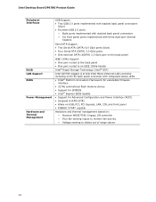
... back panel connector with integrated status LEDs • Intel® Platform Innovation Framework for extensible firmware interface • 32 Mb symmetrical flash memory device • Support for SMBIOS • Intel® Express BIOS Update • Support for Advanced Configuration and Power Interface (ACPI) • Suspend to RAM (STR) • Wake on USB, PCI, PCI Express, LAN, CIR, and front panel • ENERGY STAR* capable Hardware and thermal management based on: ― Nuvoton W83677HG-I legacy I/O controller ― Four fan...
... back panel connector with integrated status LEDs • Intel® Platform Innovation Framework for extensible firmware interface • 32 Mb symmetrical flash memory device • Support for SMBIOS • Intel® Express BIOS Update • Support for Advanced Configuration and Power Interface (ACPI) • Suspend to RAM (STR) • Wake on USB, PCI, PCI Express, LAN, CIR, and front panel • ENERGY STAR* capable Hardware and thermal management based on: ― Nuvoton W83677HG-I legacy I/O controller ― Four fan...
Product Guide
Page 13
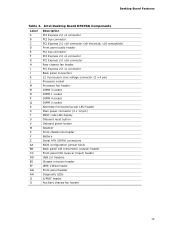
...; x16 compatible) Front panel audio header PCI bus connector PCI Express 2.0 x1 connector PCI Express 2.0 x16 connector Rear chassis fan header PCI Express 2.0 x1 connector Back panel connectors 12 V processor core voltage connector (2 x 4 pin) Processor socket Processor fan header DIMM 3 socket DIMM 1 socket DIMM 4 socket DIMM 2 socket Alternate front panel power LED header Main power connector (2 x 12 pin) POST code LED display Onboard reset button Onboard power button Speaker Front chassis fan header Battery Serial ATA (SATA) connectors BIOS configuration jumper block Back panel CIR...
...; x16 compatible) Front panel audio header PCI bus connector PCI Express 2.0 x1 connector PCI Express 2.0 x16 connector Rear chassis fan header PCI Express 2.0 x1 connector Back panel connectors 12 V processor core voltage connector (2 x 4 pin) Processor socket Processor fan header DIMM 3 socket DIMM 1 socket DIMM 4 socket DIMM 2 socket Alternate front panel power LED header Main power connector (2 x 12 pin) POST code LED display Onboard reset button Onboard power button Speaker Front chassis fan header Battery Serial ATA (SATA) connectors BIOS configuration jumper block Back panel CIR...
Product Guide
Page 19
... , you install a Serial ATA device (such as a hard drive) in card. A supervisor password and a user password can boot the computer. Setup options are then available for viewing and changing depending on whether the supervisor or user password was entered. • Setting a user password restricts who can enter either the supervisor password or the user password to Clearing Passwords on page 56. 19 Desktop Board Features BIOS The BIOS provides the Power-On Self-Test (POST), the BIOS Setup program, and the PCI/PCI Express and SATA auto-configuration utilities. Serial ATA Auto...
... , you install a Serial ATA device (such as a hard drive) in card. A supervisor password and a user password can boot the computer. Setup options are then available for viewing and changing depending on whether the supervisor or user password was entered. • Setting a user password restricts who can enter either the supervisor password or the user password to Clearing Passwords on page 56. 19 Desktop Board Features BIOS The BIOS provides the Power-On Self-Test (POST), the BIOS Setup program, and the PCI/PCI Express and SATA auto-configuration utilities. Serial ATA Auto...
Product Guide
Page 21
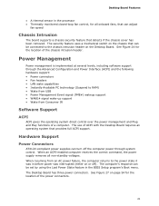
... the BIOS Setup program's Boot menu. The use of a computer. Hardware Support Power Connectors ATX12V-compliant power supplies can turn off ). When an ACPI-enabled computer receives the correct command, the power supply removes all onboard fans, that can adjust fan speed Chassis Intrusion The board supports a chassis security feature that provides full ACPI support. When resuming from Consumer IR Software Support ACPI ACPI gives the operating system direct control over the power management and Plug and Play functions of ACPI with the Desktop Board requires...
... the BIOS Setup program's Boot menu. The use of a computer. Hardware Support Power Connectors ATX12V-compliant power supplies can turn off ). When an ACPI-enabled computer receives the correct command, the power supply removes all onboard fans, that can adjust fan speed Chassis Intrusion The board supports a chassis security feature that provides full ACPI support. When resuming from Consumer IR Software Support ACPI ACPI gives the operating system direct control over the power management and Plug and Play functions of ACPI with the Desktop Board requires...

Product Guide
Page 29
...using an antistatic wrist strap and a conductive foam pad. 2 Installing and Replacing Desktop Board Components This chapter tells you how to: • Install the I/O shield • Install and remove the Desktop Board • Install and remove a processor • Install and remove memory • Install and remove a PCI Express x16 graphics card • Connect the Serial ATA cables • Connect to the internal headers • Connect to the audio system • Connect chassis fan and power supply cables • Set the BIOS configuration jumper • Clear passwords • Replace...
...using an antistatic wrist strap and a conductive foam pad. 2 Installing and Replacing Desktop Board Components This chapter tells you how to: • Install the I/O shield • Install and remove the Desktop Board • Install and remove a processor • Install and remove memory • Install and remove a PCI Express x16 graphics card • Connect the Serial ATA cables • Connect to the internal headers • Connect to the audio system • Connect chassis fan and power supply cables • Set the BIOS configuration jumper • Clear passwords • Replace...
Product Guide
Page 44
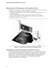
... sure you to install linked PCI Express graphics cards such as NVIDIA* SLI* (Scalable Link Interface) cards. Push the card ejector lever down using the tip of a pencil or similar tool (Figure 21, B) in "Before You Begin" on page 29. 2. Pull the card straight up to connect the two graphics cards together. Intel Desktop Board DP67BG Product Guide Removing a PCI Express x16 Graphics Card Follow these instructions to the chassis back panel. 3. Remove the screw (Figure...
... sure you to install linked PCI Express graphics cards such as NVIDIA* SLI* (Scalable Link Interface) cards. Push the card ejector lever down using the tip of a pencil or similar tool (Figure 21, B) in "Before You Begin" on page 29. 2. Pull the card straight up to connect the two graphics cards together. Intel Desktop Board DP67BG Product Guide Removing a PCI Express x16 Graphics Card Follow these instructions to the chassis back panel. 3. Remove the screw (Figure...
Product Guide
Page 48
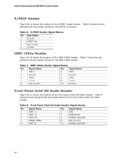
... Panel Intel HD Audio Header Signal Names Pin Signal Name 1 PORT 1L 3 PORT 1R 5 PORT 2R 7 SENSE_SEND 9 PORT 2L Pin Signal Name 2 GND 4 PRESENCE# 6 SENSE1_RETURN 8 KEY (no pin) 4 +5 VDC IEEE 1394a Header Figure 24, B shows the location of the IEEE 1394a header. Intel Desktop Board DP67BG Product Guide S/PDIF Header Figure 24, A shows the location of the front panel Intel HD Audio header. Table 7 shows the pin assignments and signal names for the front panel Intel HD Audio header. S/PDIF Header...
... Panel Intel HD Audio Header Signal Names Pin Signal Name 1 PORT 1L 3 PORT 1R 5 PORT 2R 7 SENSE_SEND 9 PORT 2L Pin Signal Name 2 GND 4 PRESENCE# 6 SENSE1_RETURN 8 KEY (no pin) 4 +5 VDC IEEE 1394a Header Figure 24, B shows the location of the IEEE 1394a header. Intel Desktop Board DP67BG Product Guide S/PDIF Header Figure 24, A shows the location of the front panel Intel HD Audio header. Table 7 shows the pin assignments and signal names for the front panel Intel HD Audio header. S/PDIF Header...
Product Guide
Page 53
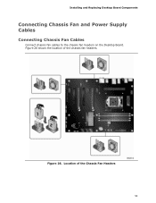
Installing and Replacing Desktop Board Components Connecting Chassis Fan and Power Supply Cables Connecting Chassis Fan Cables Connect chassis fan cables to the chassis fan headers on the Desktop Board. Location of the chassis fan headers. Figure 26 shows the location of the Chassis Fan Headers 53 Figure 26.
Installing and Replacing Desktop Board Components Connecting Chassis Fan and Power Supply Cables Connecting Chassis Fan Cables Connect chassis fan cables to the chassis fan headers on the Desktop Board. Location of the chassis fan headers. Figure 26 shows the location of the Chassis Fan Headers 53 Figure 26.
Product Guide
Page 56
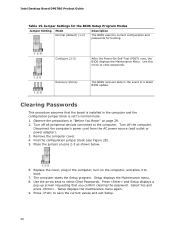
... (default) (1-2) Description The BIOS uses the current configuration and passwords for booting. Use this menu to save the current values and exit Setup. 56 Use the arrow keys to boot. 7. Press and Setup displays a pop-up screen requesting that the board is set to the computer. Observe the precautions in the computer and the configuration jumper block is installed in "Before You Begin" on pins 2-3 as shown below. 6. Turn off all peripheral devices connected...
... (default) (1-2) Description The BIOS uses the current configuration and passwords for booting. Use this menu to save the current values and exit Setup. 56 Use the arrow keys to boot. 7. Press and Setup displays a pop-up screen requesting that the board is set to the computer. Observe the precautions in the computer and the configuration jumper block is installed in "Before You Begin" on pins 2-3 as shown below. 6. Turn off all peripheral devices connected...
Product Guide
Page 65
... save this file to a removable USB device. Close all other applications. This chapter tells you how to update the BIOS by pressing the key after the Power-On Self-Test (POST) memory test begins and before the operating system boot begins. 3 Updating the BIOS The BIOS Setup program can access the BIOS Setup program by either using the Intel Express BIOS Update utility or the Iflash Memory Update utility, and how to recover the BIOS if an update fails.
... save this file to a removable USB device. Close all other applications. This chapter tells you how to update the BIOS by pressing the key after the Power-On Self-Test (POST) memory test begins and before the operating system boot begins. 3 Updating the BIOS The BIOS Setup program can access the BIOS Setup program by either using the Intel Express BIOS Update utility or the Iflash Memory Update utility, and how to recover the BIOS if an update fails.
Product Guide
Page 68
... a BIOS update failure, go to http://support.intel.com/support/motherboards/desktop/sb/CS-022312.htm. 68 At the "Welcome to the Intel Desktop Board BIOS Upgrade CD-ROM" page, press any key to upgrade the BIOS using the ISO Image BIOS file: 1. Download the ISO Image BIOS file. 2. Recovering the BIOS It is unlikely that was created in the root directory will not work. Due to BIOS size and recovery requirements, a CD-R with the .BIO file in the CD-ROM drive...
... a BIOS update failure, go to http://support.intel.com/support/motherboards/desktop/sb/CS-022312.htm. 68 At the "Welcome to the Intel Desktop Board BIOS Upgrade CD-ROM" page, press any key to upgrade the BIOS using the ISO Image BIOS file: 1. Download the ISO Image BIOS file. 2. Recovering the BIOS It is unlikely that was created in the root directory will not work. Due to BIOS size and recovery requirements, a CD-R with the .BIO file in the CD-ROM drive...
Product Guide
Page 70
... at http://support.intel.com/support/motherboards/desktop/. Intel Desktop Board DP67BG Product Guide Loading the Intel Rapid Storage Technology RAID Drivers and Software (Required for information on supported USB floppy disk drives. Once additional SATA drives have been added to the system, open the Intel Rapid Storage Technology Console Software and follow the directions to update to install a third-party SCSI or RAID driver. Refer to manage the RAID configuration. Begin Windows Setup by booting from the Windows installation CD. 2. Install the Intel® SATA RAID Controller driver...
... at http://support.intel.com/support/motherboards/desktop/. Intel Desktop Board DP67BG Product Guide Loading the Intel Rapid Storage Technology RAID Drivers and Software (Required for information on supported USB floppy disk drives. Once additional SATA drives have been added to the system, open the Intel Rapid Storage Technology Console Software and follow the directions to update to install a third-party SCSI or RAID driver. Refer to manage the RAID configuration. Begin Windows Setup by booting from the Windows installation CD. 2. Install the Intel® SATA RAID Controller driver...
Product Guide
Page 71
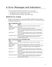
... the system powers up , then off for 0.5 seconds. A Error Messages and Indicators Intel Desktop Board DP67BG reports POST errors in progress Off when the update begins, then on the monitor • By displaying diagnostic progress codes (POST codes) BIOS Error Codes Whenever a recoverable error occurs during POST, the BIOS causes the board's speaker to beep and the front panel power LED to blink an error message indicating the problem (see Table 16). Front-panel Power LED Blink Codes Type Pattern Processor On when...
... the system powers up , then off for 0.5 seconds. A Error Messages and Indicators Intel Desktop Board DP67BG reports POST errors in progress Off when the update begins, then on the monitor • By displaying diagnostic progress codes (POST codes) BIOS Error Codes Whenever a recoverable error occurs during POST, the BIOS causes the board's speaker to beep and the front panel power LED to blink an error message indicating the problem (see Table 16). Front-panel Power LED Blink Codes Type Pattern Processor On when...
Product Guide
Page 73
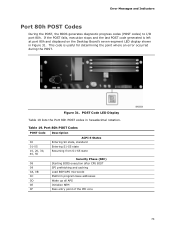
.... This code is left at port 80h and displayed on the Desktop Board's seven-segment LED display shown in hexadecimal notation. Port 80h POST Codes POST Code Description 00 01-05 10, 20, 30, 40, 50 ACPI S States Entering S0 state, standard Entering S1-S5 state Resuming from S1-S5 state 08 09 0A, 0B 0C 0D 0E 0F Security Phase (SEC) Starting BIOS execution after CPU BIST...
.... This code is left at port 80h and displayed on the Desktop Board's seven-segment LED display shown in hexadecimal notation. Port 80h POST Codes POST Code Description 00 01-05 10, 20, 30, 40, 50 ACPI S States Entering S0 state, standard Entering S1-S5 state Resuming from S1-S5 state 08 09 0A, 0B 0C 0D 0E 0F Security Phase (SEC) Starting BIOS execution after CPU BIST...
Product Guide
Page 74
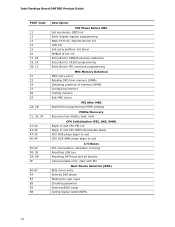
Intel Desktop Board DP67BG Product Guide POST Code 11 12 13 14 15 16 17, 18 19, 1A 1B, 1C 21 23 24 27 28 29 2A, 2B 31, 33, 34...memory DIMMs Configuring memory Testing memory Exit MRC driver PEI After MRC Start/finish programming MTRR settings PEIMs/Recovery Recovery has initiate, load, valid CPU Initialization (PEI, DXE, SMM) Begin to end CPU PEI init Begin to end CPU SMM init/relocate bases CPU DXE phase begin to end CPU DXE SMM phase begin to end I/O Buses PCI enumeration, allocation, hot plug Resetting USB bus Resetting SATA bus and all devices Unrecoverable error, start with PIC Boot Device...
Intel Desktop Board DP67BG Product Guide POST Code 11 12 13 14 15 16 17, 18 19, 1A 1B, 1C 21 23 24 27 28 29 2A, 2B 31, 33, 34...memory DIMMs Configuring memory Testing memory Exit MRC driver PEI After MRC Start/finish programming MTRR settings PEIMs/Recovery Recovery has initiate, load, valid CPU Initialization (PEI, DXE, SMM) Begin to end CPU PEI init Begin to end CPU SMM init/relocate bases CPU DXE phase begin to end CPU DXE SMM phase begin to end I/O Buses PCI enumeration, allocation, hot plug Resetting USB bus Resetting SATA bus and all devices Unrecoverable error, start with PIC Boot Device...


