
Product Specification
Page 8
...3.5 Legacy USB Support 61 3.6 BIOS Updates 62 3.6.1 Language Support 62 3.6.2 Custom Splash Screen 63 3.7 BIOS Recovery 63 3.8 Boot Options 64 3.8.1 Optical Drive Boot 64 3.8.2 Network Boot 64 3.8.3 Booting Without Attached Devices 64 3.8.4 Changing the Default Boot Device During POST 64 3.9 Adjusting Boot Speed 65 3.9.1 Peripheral Selection and Configuration 65 3.9.2 BIOS Boot Optimizations 65 3.10 BIOS Security Features 66 3.11 BIOS Performance Features 67 4 Error Messages and Beep Codes 4.1 Speaker 69 4.2 BIOS Beep Codes 69 4.3 Front-panel Power LED Blink Codes 70 4.4 BIOS...
...3.5 Legacy USB Support 61 3.6 BIOS Updates 62 3.6.1 Language Support 62 3.6.2 Custom Splash Screen 63 3.7 BIOS Recovery 63 3.8 Boot Options 64 3.8.1 Optical Drive Boot 64 3.8.2 Network Boot 64 3.8.3 Booting Without Attached Devices 64 3.8.4 Changing the Default Boot Device During POST 64 3.9 Adjusting Boot Speed 65 3.9.1 Peripheral Selection and Configuration 65 3.9.2 BIOS Boot Optimizations 65 3.10 BIOS Security Features 66 3.11 BIOS Performance Features 67 4 Error Messages and Beep Codes 4.1 Speaker 69 4.2 BIOS Beep Codes 69 4.3 Front-panel Power LED Blink Codes 70 4.4 BIOS...
Product Specification
Page 9
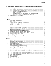
... and Fan Headers 29 7. System Memory Map 39 10. Major Board Components 13 2. Memory Channel and DIMM Configuration 20 4. Location of the Jumper Block 50 14. Connection Diagram for Front Panel USB 2.0 Headers 49 13. LAN Connector LED States 27 6. Front Panel USB Headers 43 15. Localized High Temperature Zones 55 Tables 1. Wake-up Devices and Events 32 9. Front Panel Audio Header for Intel HD Audio 43 13. Location of the Standby Power LED 36 8. Detailed System Memory Address Map 38 9. Front Panel Audio Header for...
... and Fan Headers 29 7. System Memory Map 39 10. Major Board Components 13 2. Memory Channel and DIMM Configuration 20 4. Location of the Jumper Block 50 14. Connection Diagram for Front Panel USB 2.0 Headers 49 13. LAN Connector LED States 27 6. Front Panel USB Headers 43 15. Localized High Temperature Zones 55 Tables 1. Wake-up Devices and Events 32 9. Front Panel Audio Header for Intel HD Audio 43 13. Location of the Standby Power LED 36 8. Detailed System Memory Address Map 38 9. Front Panel Audio Header for...
Product Specification
Page 10
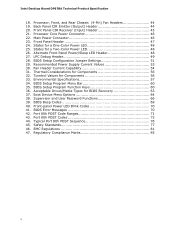
.... Processor Core Power Connector 46 22. BIOS Setup Configuration Jumper Settings 51 29. BIOS Beep Codes 69 40. Front-panel Power LED Blink Codes 70 41. Port 80h POST Code Ranges 71 43. Processor, Front, and Rear Chassis (4-Pin) Fan Headers 44 19. Recommended Power Supply Current Values 53 30. Environmental Specifications 57 34. BIOS Setup Program Function Keys 60 36. Port 80h POST Codes 72 44. Safety Standards 77 46. Front Panel Header 47 24. States for BIOS Recovery 63 37. LPC Debug Header 49 28. Acceptable Drives...
.... Processor Core Power Connector 46 22. BIOS Setup Configuration Jumper Settings 51 29. BIOS Beep Codes 69 40. Front-panel Power LED Blink Codes 70 41. Port 80h POST Code Ranges 71 43. Processor, Front, and Rear Chassis (4-Pin) Fan Headers 44 19. Recommended Power Supply Current Values 53 30. Environmental Specifications 57 34. BIOS Setup Program Function Keys 60 36. Port 80h POST Codes 72 44. Safety Standards 77 46. Front Panel Header 47 24. States for BIOS Recovery 63 37. LPC Debug Header 49 28. Acceptable Drives...
Product Specification
Page 11
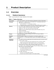
...PCH) Graphics Audio Peripheral Interfaces Discrete graphics support for PCI Express 2.0 x16 add-in graphics card 10-channel (7.1 + 2) Intel High Definition Audio via the Realtek ALC892 audio codec • Two USB 3.0 ports are implemented with stacked back panel connectors (blue) • Fourteen USB 2.0 ports: ― Six ports are implemented with stacked back panel connectors (black) ― Eight front panel ports implemented through four internal headers • Two Serial ATA (SATA) 6.0 Gb/s interfaces through the Intel P67 Express Chipset with Intel® Rapid Storage Technology RAID...
...PCH) Graphics Audio Peripheral Interfaces Discrete graphics support for PCI Express 2.0 x16 add-in graphics card 10-channel (7.1 + 2) Intel High Definition Audio via the Realtek ALC892 audio codec • Two USB 3.0 ports are implemented with stacked back panel connectors (blue) • Fourteen USB 2.0 ports: ― Six ports are implemented with stacked back panel connectors (black) ― Eight front panel ports implemented through four internal headers • Two Serial ATA (SATA) 6.0 Gb/s interfaces through the Intel P67 Express Chipset with Intel® Rapid Storage Technology RAID...

Product Specification
Page 12
...; Two PCI Express 2.0 x1 add-in card connectors • Three Conventional PCI bus connector • Intel® BIOS resident in the SPI Flash device • Support for Advanced Configuration and Power Interface (ACPI), Plug and Play, and SMBIOS • Support for PCI* Local Bus Specification Revision 2.2 • Support for PCI Express* Revision 2.0 • Suspend to RAM support • Wake on PCI, PCI Express, LAN, front panel, Consumer Infrared (CIR), and USB ports Gigabit (10/100/1000 Mbits/s) LAN subsystem using the Intel® 82579V Gigabit Ethernet Controller Legacy I/O Control...
...; Two PCI Express 2.0 x1 add-in card connectors • Three Conventional PCI bus connector • Intel® BIOS resident in the SPI Flash device • Support for Advanced Configuration and Power Interface (ACPI), Plug and Play, and SMBIOS • Support for PCI* Local Bus Specification Revision 2.2 • Support for PCI Express* Revision 2.0 • Suspend to RAM support • Wake on PCI, PCI Express, LAN, front panel, Consumer Infrared (CIR), and USB ports Gigabit (10/100/1000 Mbits/s) LAN subsystem using the Intel® 82579V Gigabit Ethernet Controller Legacy I/O Control...

Product Specification
Page 14
... fan header Chassis intrusion header Low Pin Count (LPC) Debug header Consumer IR emitter (output) header Consumer IR receiver (input) header Main power connector (2 x 12) Battery Piezoelectric speaker SATA connectors (5) Alternate front panel power LED header Front panel header BIOS Setup configuration jumper block Standby power LED Front panel USB 2.0 headers (4) Intel P67 Express Chipset S/PDIF out header Front panel audio header 14 Table 2. Components Shown in Figure 1 Item/callout from Figure 1 A B C D E F G H I J K L M N O P Q R S T U V W X Y Z AA BB CC DD EE FF GG Description PCI...
... fan header Chassis intrusion header Low Pin Count (LPC) Debug header Consumer IR emitter (output) header Consumer IR receiver (input) header Main power connector (2 x 12) Battery Piezoelectric speaker SATA connectors (5) Alternate front panel power LED header Front panel header BIOS Setup configuration jumper block Standby power LED Front panel USB 2.0 headers (4) Intel P67 Express Chipset S/PDIF out header Front panel audio header 14 Table 2. Components Shown in Figure 1 Item/callout from Figure 1 A B C D E F G H I J K L M N O P Q R S T U V W X Y Z AA BB CC DD EE FF GG Description PCI...

Product Specification
Page 16
...: • No parallel port connector • No floppy drive connector • No serial port connector or header • No PS/2 connectors • No PATA connector 1.3 Online Support To find information about... Intel Desktop Board DP67BA Desktop Board Support Available configurations for Intel Desktop Board DP67BA Visit this World Wide Web site: http://www.intel.com/products/motherboard/index.htm http://www.intel.com/p/en_US/support?iid=hdr+support http://ark.intel.com Supported processors Chipset information BIOS and driver updates Tested memory Integration information http...
...: • No parallel port connector • No floppy drive connector • No serial port connector or header • No PS/2 connectors • No PATA connector 1.3 Online Support To find information about... Intel Desktop Board DP67BA Desktop Board Support Available configurations for Intel Desktop Board DP67BA Visit this World Wide Web site: http://www.intel.com/products/motherboard/index.htm http://www.intel.com/p/en_US/support?iid=hdr+support http://ark.intel.com Supported processors Chipset information BIOS and driver updates Tested memory Integration information http...
Product Specification
Page 18
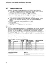
... structure. Intel Desktop Board DP67BA Technical Product Specification 1.5 System Memory The board has four DIMM sockets and supports the following restriction: Double-sided DIMMs with x16 organization are not supported. • 32 GB maximum total system memory (with 4 Gb memory technology). Table 3. Refer to support higher performance DDR3 SDRAM DIMMs. • Support for 1.35 V Low Voltage DDR3 (new JEDEC specification) • Two independent memory channels with interleaved mode support •...
... structure. Intel Desktop Board DP67BA Technical Product Specification 1.5 System Memory The board has four DIMM sockets and supports the following restriction: Double-sided DIMMs with x16 organization are not supported. • 32 GB maximum total system memory (with 4 Gb memory technology). Table 3. Refer to support higher performance DDR3 SDRAM DIMMs. • Support for 1.35 V Low Voltage DDR3 (new JEDEC specification) • Two independent memory channels with interleaved mode support •...

Product Specification
Page 22
... legacy and native modes. For information about The location of 6 Gb/s for two ports and 3 Gb/s for host to device connections. A point-to-point interface is the preferred mode for configurations using the Windows* XP, Windows Vista*, and Windows 7* operating systems. NOTE Many SATA drives use new low-voltage power connectors and require adapters or power supplies equipped with a theoretical maximum transfer rate of the SATA connectors Refer to the operating system. Intel Desktop Board...
... legacy and native modes. For information about The location of 6 Gb/s for two ports and 3 Gb/s for host to device connections. A point-to-point interface is the preferred mode for configurations using the Windows* XP, Windows Vista*, and Windows 7* operating systems. NOTE Many SATA drives use new low-voltage power connectors and require adapters or power supplies equipped with a theoretical maximum transfer rate of the SATA connectors Refer to the operating system. Intel Desktop Board...
Product Specification
Page 23
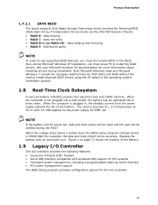
... wake-up event interface • PCI power management support The BIOS Setup program provides configuration options for more information about installing drivers during the POST. See your Microsoft Windows XP documentation for the I /O controller provides the following RAID (Redundant Array of three years. NOTE If the battery and AC power fail, date and time values will be reset and the user will be accurate. Product Description 1.7.1.1 SATA RAID The board supports Intel Rapid Storage Technology...
... wake-up event interface • PCI power management support The BIOS Setup program provides configuration options for more information about installing drivers during the POST. See your Microsoft Windows XP documentation for the I /O controller provides the following RAID (Redundant Array of three years. NOTE If the battery and AC power fail, date and time values will be reset and the user will be accurate. Product Description 1.7.1.1 SATA RAID The board supports Intel Rapid Storage Technology...
Product Specification
Page 26
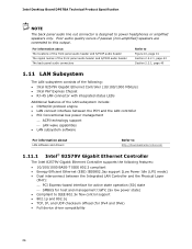
... Express Chipset • RJ-45 LAN connector with integrated status LEDs Additional features of the LAN subsystem include: • CSMA/CD protocol engine • LAN connect interface between the PCH and the LAN controller • PCI Conventional bus power management ⎯ ACPI technology support ⎯ LAN wake capabilities • LAN subsystem software For information about LAN software and drivers Refer to http://downloadcenter.intel.com 1.11.1 Intel® 82579V Gigabit Ethernet Controller The Intel 82579V Gigabit Ethernet Controller supports...
... Express Chipset • RJ-45 LAN connector with integrated status LEDs Additional features of the LAN subsystem include: • CSMA/CD protocol engine • LAN connect interface between the PCH and the LAN controller • PCI Conventional bus power management ⎯ ACPI technology support ⎯ LAN wake capabilities • LAN subsystem software For information about LAN software and drivers Refer to http://downloadcenter.intel.com 1.11.1 Intel® 82579V Gigabit Ethernet Controller The Intel 82579V Gigabit Ethernet Controller supports...

Product Specification
Page 30
...: • Plug and Play (including bus and device enumeration) • Power management control of ACPI with an ACPI-aware operating system. working state) On (ACPI G0 - Intel Desktop Board DP67BA Technical Product Specification 1.13 Power Management Power management is implemented at several levels, including: • Software support through Advanced Configuration and Power Interface (ACPI) • Hardware support: ⎯ Power connector ⎯ Fan headers ⎯ LAN wake capabilities ⎯ Instantly Available PC technology ⎯ Wake from USB ⎯ Power Management Event...
...: • Plug and Play (including bus and device enumeration) • Power management control of ACPI with an ACPI-aware operating system. working state) On (ACPI G0 - Intel Desktop Board DP67BA Technical Product Specification 1.13 Power Management Power management is implemented at several levels, including: • Software support through Advanced Configuration and Power Interface (ACPI) • Hardware support: ⎯ Power connector ⎯ Fan headers ⎯ LAN wake capabilities ⎯ Instantly Available PC technology ⎯ Wake from USB ⎯ Power Management Event...

Product Specification
Page 49
... last POST code generated is useful for high-speed USB devices. LPC Debug Header Pin Signal Name 1 CK_33M_DEBUG 3 PLTRST# 5 LAD0 7 LAD2 9 GND 11 +3.3 V 13 Not Connected Pin Signal Name 2 GND 4 LFRAME# 6 LAD1 8 LAD3 10 GND 12 +3.3 V 14 +3.3 V 49 Connection Diagram for the front panel USB 2.0 headers. Displaying the POST codes requires a POST card that can decode the port and display the contents on the USB headers is fused. • Use only a front panel USB connector that conforms to I/O port 80h...
... last POST code generated is useful for high-speed USB devices. LPC Debug Header Pin Signal Name 1 CK_33M_DEBUG 3 PLTRST# 5 LAD0 7 LAD2 9 GND 11 +3.3 V 13 Not Connected Pin Signal Name 2 GND 4 LFRAME# 6 LAD1 8 LAD3 10 GND 12 +3.3 V 14 +3.3 V 49 Connection Diagram for the front panel USB 2.0 headers. Displaying the POST codes requires a POST card that can decode the port and display the contents on the USB headers is fused. • Use only a front panel USB connector that conforms to I/O port 80h...

Product Specification
Page 59
... of BIOS and a revision code. The BIOS Setup program is in the Serial Peripheral Interface Flash Memory (SPI Flash) and can be updated using a disk-based program. The BIOS displays a message during POST identifying the type of BIOS Features 3.1 Introduction The board uses an Intel BIOS that is stored in configure mode. Maintenance Main Configuration Performance Security Power Boot Exit NOTE The maintenance menu is displayed only when the board is accessed by pressing the key after the Power-On Self-Test (POST) memory...
... of BIOS and a revision code. The BIOS Setup program is in the Serial Peripheral Interface Flash Memory (SPI Flash) and can be updated using a disk-based program. The BIOS displays a message during POST identifying the type of BIOS Features 3.1 Introduction The board uses an Intel BIOS that is stored in configure mode. Maintenance Main Configuration Performance Security Power Boot Exit NOTE The maintenance menu is displayed only when the board is accessed by pressing the key after the Power-On Self-Test (POST) memory...

Product Specification
Page 60
... lets a user insert or remove PCI cards without having to Setup program options Table 35 lists the function keys available for menu screens. tion Performance Clears passwords and displays processor information Displays processor and memory configuration Configures advanced features available through the chipset Configures Memory, Bus and Processor overrides Security Sets passwords and security features Power Configures power management features and power supply controls Boot Selects boot options Exit Saves or discards changes to configure the system. Intel Desktop Board DP67BA...
... lets a user insert or remove PCI cards without having to Setup program options Table 35 lists the function keys available for menu screens. tion Performance Clears passwords and displays processor information Displays processor and memory configuration Configures advanced features available through the chipset Configures Memory, Bus and Processor overrides Security Sets passwords and security features Power Configures power management features and power supply controls Boot Selects boot options Exit Saves or discards changes to configure the system. Intel Desktop Board DP67BA...
Product Specification
Page 61
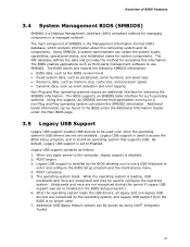
...-Plug and Play operating system can be found in a managed network. The BIOS supports an SMBIOS table interface for accessing this period if Legacy USB support was set to use a USB keyboard to Disabled in the BIOS Setup program.) 6. Legacy USB support is enabled by the BIOS allowing you apply power to configure the operating system. (Keyboards and mice are recognized by using Intel® Integrator Toolkit. 61 Legacy USB support is used . 7. After the operating system loads the USB drivers, all legacy...
...-Plug and Play operating system can be found in a managed network. The BIOS supports an SMBIOS table interface for accessing this period if Legacy USB support was set to use a USB keyboard to Disabled in the BIOS Setup program.) 6. Legacy USB support is enabled by the BIOS allowing you apply power to configure the operating system. (Keyboards and mice are recognized by using Intel® Integrator Toolkit. 61 Legacy USB support is used . 7. After the operating system loads the USB drivers, all legacy...

Product Specification
Page 64
... drive to the El Torito bootable CD-ROM format specification. This menu displays the list of available boot devices. Boot devices are not present: • Video adapter • Keyboard • Mouse 3.8.4 Changing the Default Boot Device During POST Pressing the key during POST automatically forces booting from the selected device Exits the menu and boots according to boot from the onboard LAN or a network add-in priority order. Boot Device Menu Options Boot Device Menu Function Keys or Description Selects a default boot device Exits the menu, and boots from the LAN...
... drive to the El Torito bootable CD-ROM format specification. This menu displays the list of available boot devices. Boot devices are not present: • Video adapter • Keyboard • Mouse 3.8.4 Changing the Default Boot Device During POST Pressing the key during POST automatically forces booting from the selected device Exits the menu and boots according to boot from the onboard LAN or a network add-in priority order. Boot Device Menu Options Boot Device Menu Function Keys or Description Selects a default boot device Exits the menu, and boots from the LAN...
Product Specification
Page 66
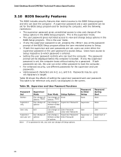
.... Intel Desktop Board DP67BA Technical Product Specification 3.10 BIOS Security Features The BIOS includes security features that restrict access to which password is entered. • Setting the user password restricts who can boot the computer. The password prompt will be up to view and change all the Setup options in the BIOS Setup program. Password to view and change a Supervisor Password limited number Enter Password of setting the supervisor password and user password. This is set for the BIOS Setup program...
.... Intel Desktop Board DP67BA Technical Product Specification 3.10 BIOS Security Features The BIOS includes security features that restrict access to which password is entered. • Setting the user password restricts who can boot the computer. The password prompt will be up to view and change all the Setup options in the BIOS Setup program. Password to view and change a Supervisor Password limited number Enter Password of setting the supervisor password and user password. This is set for the BIOS Setup program...

Product Specification
Page 70
...), entire pattern repeats (blink and pause) until the system is found. 4.4 BIOS Error Messages Table 41 lists the error messages and provides a brief description of 16 blinks. Intel Desktop Board DP67BA Technical Product Specification 4.3 Front-panel Power LED Blink Codes Whenever a recoverable error occurs during POST, the BIOS causes the board's front panel power LED to boot. 70 Run Setup to reset values. Table 40. CMOS memory may be losing power. If no VGA option ROM is powered off .
...), entire pattern repeats (blink and pause) until the system is found. 4.4 BIOS Error Messages Table 41 lists the error messages and provides a brief description of 16 blinks. Intel Desktop Board DP67BA Technical Product Specification 4.3 Front-panel Power LED Blink Codes Whenever a recoverable error occurs during POST, the BIOS causes the board's front panel power LED to boot. 70 Run Setup to reset values. Table 40. CMOS memory may be losing power. If no VGA option ROM is powered off .

Product Specification
Page 71
... POST card can interface with PCI. Error Messages and Beep Codes 4.5 Port 80h POST Codes During the POST, the BIOS generates diagnostic progress codes (POST codes) to I /O Buses: PCI, USB, ATA etc. 0x5F is useful for determining the point where an error occurred. Refer to S5. Start with the Low Pin Count (LPC) Debug header. Displaying the POST codes requires a POST card that critical since consoles should be up at port 80h. S2, 0x30 - For future use Boot Devices: Includes...
... POST card can interface with PCI. Error Messages and Beep Codes 4.5 Port 80h POST Codes During the POST, the BIOS generates diagnostic progress codes (POST codes) to I /O Buses: PCI, USB, ATA etc. 0x5F is useful for determining the point where an error occurred. Refer to S5. Start with the Low Pin Count (LPC) Debug header. Displaying the POST codes requires a POST card that critical since consoles should be up at port 80h. S2, 0x30 - For future use Boot Devices: Includes...


