Product Specification
Page 7
... Summary 11 1.1.2 Board Layout 13 1.1.3 Block Diagram 15 1.2 Legacy Considerations 16 1.3 Online Support 16 1.4 Processor 17 1.4.1 PCI Express x16 Graphics 17 1.5 System Memory 18 1.5.1 Memory Configurations 19 1.6 Intel® P67 Express Chipset 21 1.6.1 USB 21 1.7 SATA Interfaces 22 1.8 Real-Time Clock Subsystem 23 1.9...10 Audio Subsystem 24 1.10.1 Audio Subsystem Software 25 1.10.2 Audio Subsystem Components 25 1.11 LAN Subsystem 26 1.11.1 Intel® 82579V Gigabit Ethernet Controller 26 1.11.2 LAN Subsystem Software 27 1.11.3 RJ-45 LAN Connector with Integrated LEDs 27...
... Summary 11 1.1.2 Board Layout 13 1.1.3 Block Diagram 15 1.2 Legacy Considerations 16 1.3 Online Support 16 1.4 Processor 17 1.4.1 PCI Express x16 Graphics 17 1.5 System Memory 18 1.5.1 Memory Configurations 19 1.6 Intel® P67 Express Chipset 21 1.6.1 USB 21 1.7 SATA Interfaces 22 1.8 Real-Time Clock Subsystem 23 1.9...10 Audio Subsystem 24 1.10.1 Audio Subsystem Software 25 1.10.2 Audio Subsystem Components 25 1.11 LAN Subsystem 26 1.11.1 Intel® 82579V Gigabit Ethernet Controller 26 1.11.2 LAN Subsystem Software 27 1.11.3 RJ-45 LAN Connector with Integrated LEDs 27...
Product Specification
Page 10
... 35. States for BIOS Recovery 63 37. Tcontrol Values for Components 56 32. Regulatory Compliance Marks 85 x Processor, Front, and Rear Chassis (4-Pin) Fan Headers 44 19. Typical Port 80h POST Sequence 76 45. Intel Desktop Board DP67BA Technical Product Specification 18. Front Panel Header 47 24. Alternate Front Panel Power/Sleep...
... 35. States for BIOS Recovery 63 37. Tcontrol Values for Components 56 32. Regulatory Compliance Marks 85 x Processor, Front, and Rear Chassis (4-Pin) Fan Headers 44 19. Typical Port 80h POST Sequence 76 45. Intel Desktop Board DP67BA Technical Product Specification 18. Front Panel Header 47 24. Alternate Front Panel Power/Sleep...
Product Specification
Page 11
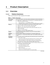
... Chipset ATX (9.60 inches by 11.60 inches [243.84 millimeters by 294.64 millimeters]) • Intel® Core™ i7, Intel® Core™ i5, and Intel Core™ i3 processors with up to 95W TDP in an LGA1155 socket ― One PCI Express* 2.0 x16 graphics interface... Platform Controller Hub (PCH) Graphics Audio Peripheral Interfaces Discrete graphics support for PCI Express 2.0 x16 add-in graphics card 10-channel (7.1 + 2) Intel High Definition Audio via the Realtek ALC892 audio codec • Two USB 3.0 ports are implemented with stacked back panel connectors (blue) • ...
... Chipset ATX (9.60 inches by 11.60 inches [243.84 millimeters by 294.64 millimeters]) • Intel® Core™ i7, Intel® Core™ i5, and Intel Core™ i3 processors with up to 95W TDP in an LGA1155 socket ― One PCI Express* 2.0 x16 graphics interface... Platform Controller Hub (PCH) Graphics Audio Peripheral Interfaces Discrete graphics support for PCI Express 2.0 x16 add-in graphics card 10-channel (7.1 + 2) Intel High Definition Audio via the Realtek ALC892 audio codec • Two USB 3.0 ports are implemented with stacked back panel connectors (blue) • ...

Product Specification
Page 14
Table 2. Intel Desktop Board DP67BA Technical Product Specification Table 2 lists the components identified in card connector Back panel connectors Processor core power connector (2 x 2) Rear chassis fan header LGA1155 processor socket Processor fan header DIMM 3 (Channel A DIMM 0) DIMM... SATA connectors (5) Alternate front panel power LED header Front panel header BIOS Setup configuration jumper block Standby power LED Front panel USB 2.0 headers (4) Intel P67 Express Chipset S/PDIF out header Front panel audio header 14 Components Shown in Figure 1 Item/callout from Figure 1 A B C D E...
Table 2. Intel Desktop Board DP67BA Technical Product Specification Table 2 lists the components identified in card connector Back panel connectors Processor core power connector (2 x 2) Rear chassis fan header LGA1155 processor socket Processor fan header DIMM 3 (Channel A DIMM 0) DIMM... SATA connectors (5) Alternate front panel power LED header Front panel header BIOS Setup configuration jumper block Standby power LED Front panel USB 2.0 headers (4) Intel P67 Express Chipset S/PDIF out header Front panel audio header 14 Components Shown in Figure 1 Item/callout from Figure 1 A B C D E...

Product Specification
Page 16
...=hdr+support http://ark.intel.com Supported processors Chipset information BIOS and driver updates Tested memory Integration information http://processormatch.intel.com http://www.intel.com/products/desktop/chipsets/index.htm http://downloadcenter.intel.com http://www.intel.com/support/motherboards/desktop/sb/CS025414.htm http://www.intel.com/support/go/buildit 16 Intel Desktop Board DP67BA Technical...
...=hdr+support http://ark.intel.com Supported processors Chipset information BIOS and driver updates Tested memory Integration information http://processormatch.intel.com http://www.intel.com/products/desktop/chipsets/index.htm http://downloadcenter.intel.com http://www.intel.com/support/motherboards/desktop/sb/CS025414.htm http://www.intel.com/support/go/buildit 16 Intel Desktop Board DP67BA Technical...
Product Specification
Page 17
...the interface is designed to support the Intel Core i7, Intel Core i5, and Intel Core i3 processors in an LGA1155 socket Other processors may be supported in the future. See the Intel web site listed below for the most up-to the processor. NOTE This board has specific requirements... Board DP67BA. The maximum theoretical bandwidth on power supply requirements for this board. 1.4.1 PCI Express x16 Graphics The Intel Core i7, Intel Core i5, and Intel Core i3 processors in an LGA1155 socket support discrete add in graphics cards via the PCI Express 2.0 x16 graphics connector: • ...
...the interface is designed to support the Intel Core i7, Intel Core i5, and Intel Core i3 processors in an LGA1155 socket Other processors may be supported in the future. See the Intel web site listed below for the most up-to the processor. NOTE This board has specific requirements... Board DP67BA. The maximum theoretical bandwidth on power supply requirements for this board. 1.4.1 PCI Express x16 Graphics The Intel Core i7, Intel Core i5, and Intel Core i3 processors in an LGA1155 socket support discrete add in graphics cards via the PCI Express 2.0 x16 graphics connector: • ...
Product Specification
Page 19
... is nearest to the 8 GB address space limit), if any, is necessary to : http://www.intel.com/support/motherboards/desktop/sb/cs011965.htm 19 Product Description 1.5.1 Memory Configurations The Intel Core i7, Intel Core i5, and Intel Core i3 processors in multiple zones of dual and single channel operation across the whole of memory organization...
... is nearest to the 8 GB address space limit), if any, is necessary to : http://www.intel.com/support/motherboards/desktop/sb/cs011965.htm 19 Product Description 1.5.1 Memory Configurations The Intel Core i7, Intel Core i5, and Intel Core i3 processors in multiple zones of dual and single channel operation across the whole of memory organization...
Product Specification
Page 20
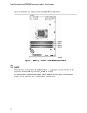
For best memory performance always install memory into the blue DIMM memory sockets if only installing two DIMMs in the DIMM 1 (Channel A, DIMM 0) socket. Figure 3. Intel Desktop Board DP67BA Technical Product Specification Figure 3 illustrates the memory channel and DIMM configuration. Memory Channel and DIMM Configuration NOTE The Intel Core i7, Intel Core i5, and Intel Core i3 processors require memory to be populated in your configuration. 20
For best memory performance always install memory into the blue DIMM memory sockets if only installing two DIMMs in the DIMM 1 (Channel A, DIMM 0) socket. Figure 3. Intel Desktop Board DP67BA Technical Product Specification Figure 3 illustrates the memory channel and DIMM configuration. Memory Channel and DIMM Configuration NOTE The Intel Core i7, Intel Core i5, and Intel Core i3 processors require memory to be populated in your configuration. 20

Product Specification
Page 21
... Refer to 14 USB 2.0 ports and two USB 3.0 ports. The Intel P67 Express Chipset is attached to the processor and the USB, SATA, LPC, LAN, and PCI Express interfaces. For information about The Intel P67 chipset Resources used by the NEC* UPD720200 controller. The USB 3.0... ports are provided by the chipset Refer to http://www.intel.com/products/desktop/chipsets/...
... Refer to 14 USB 2.0 ports and two USB 3.0 ports. The Intel P67 Express Chipset is attached to the processor and the USB, SATA, LPC, LAN, and PCI Express interfaces. For information about The Intel P67 chipset Resources used by the NEC* UPD720200 controller. The USB 3.0... ports are provided by the chipset Refer to http://www.intel.com/products/desktop/chipsets/...

Product Specification
Page 28
... detects if the chassis cover is removed. The security feature uses a mechanical switch on the Winbond W83677HG-I device, which supports the following: • Processor and system ambient temperature monitoring • Chassis fan speed monitoring • Power monitoring of +12 V, +5 V, +3.3 V, V_SM and +VCCP •... information about The functions of the chassis intrusion header Refer to Figure 10, page 41 28 Intel Desktop Board DP67BA Technical Product Specification 1.12 Hardware Management Subsystem The hardware management features enable the board to be implemented using...
... detects if the chassis cover is removed. The security feature uses a mechanical switch on the Winbond W83677HG-I device, which supports the following: • Processor and system ambient temperature monitoring • Chassis fan speed monitoring • Power monitoring of +12 V, +5 V, +3.3 V, V_SM and +VCCP •... information about The functions of the chassis intrusion header Refer to Figure 10, page 41 28 Intel Desktop Board DP67BA Technical Product Specification 1.12 Hardware Management Subsystem The hardware management features enable the board to be implemented using...

Product Specification
Page 29
Thermal Sensors and Fan Headers 29 Product Description 1.12.4 Thermal Monitoring Figure 6 shows the locations of the thermal sensors and fan headers. Item A B C D E F Description Rear chassis fan header Thermal diode, located on the processor die Remote thermal diode Processor fan header Front chassis fan header Thermal diode, located on the Intel P67 PCH Figure 6.
Thermal Sensors and Fan Headers 29 Product Description 1.12.4 Thermal Monitoring Figure 6 shows the locations of the thermal sensors and fan headers. Item A B C D E F Description Rear chassis fan header Thermal diode, located on the processor die Remote thermal diode Processor fan header Front chassis fan header Thermal diode, located on the Intel P67 PCH Figure 6.
Product Specification
Page 31
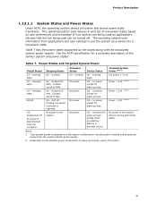
The operating system uses information from the computer. Power States and Targeted System Power Global States Sleeping States Processor States Device States Targeted System Power (Note 1) G0 - Full power > 30 W G1 - Context saved to put the system as a whole into a low-power state. No ...
The operating system uses information from the computer. Power States and Targeted System Power Global States Sleeping States Processor States Device States Targeted System Power (Note 1) G0 - Full power > 30 W G1 - Context saved to put the system as a whole into a low-power state. No ...

Product Specification
Page 42
Intel Desktop Board DP67BA Technical Product Specification Table 10 lists the component-side connectors and headers identified in card connector H Processor core power connector (2 x 2) I Rear chassis fan header J Processor fan header K Front chassis fan header L Chassis intrusion header M LPC Debug header N Consumer IR emitter (output) header O Consumer IR receiver (input) header P Main power connector...
Intel Desktop Board DP67BA Technical Product Specification Table 10 lists the component-side connectors and headers identified in card connector H Processor core power connector (2 x 2) I Rear chassis fan header J Processor fan header K Front chassis fan header L Chassis intrusion header M LPC Debug header N Consumer IR emitter (output) header O Consumer IR receiver (input) header P Main power connector...

Product Specification
Page 44
...7 Ground Table 16. Table 19. S/PDIF Header Pin Signal Name 1 Ground 2 S/PDIF out 3 Key (no pin) 5 Jack detect 1 6 Jack detect 2 44 Processor, Front, and Rear Chassis (4-Pin) Fan Headers Pin 1 2 3 Signal Name Ground (Note) +12 V FAN_TACH 4 FAN_CONTROL Note: These fan headers use Pulse Width Modulation...Output) Header Pin Signal Name 1 Emitter out 1 2 Emitter out 2 3 Ground 4 Key (no pin) 4 +5 V DC Table 17. Intel Desktop Board DP67BA Technical Product Specification Table 15. Chassis Intrusion Header Pin Signal Name 1 Intruder# 2 Ground Table 18.
...7 Ground Table 16. Table 19. S/PDIF Header Pin Signal Name 1 Ground 2 S/PDIF out 3 Key (no pin) 5 Jack detect 1 6 Jack detect 2 44 Processor, Front, and Rear Chassis (4-Pin) Fan Headers Pin 1 2 3 Signal Name Ground (Note) +12 V FAN_TACH 4 FAN_CONTROL Note: These fan headers use Pulse Width Modulation...Output) Header Pin Signal Name 1 Emitter out 1 2 Emitter out 2 3 Ground 4 Key (no pin) 4 +5 V DC Table 17. Intel Desktop Board DP67BA Technical Product Specification Table 15. Chassis Intrusion Header Pin Signal Name 1 Intruder# 2 Ground Table 18.

Product Specification
Page 46
..., this pin will prevent the board from booting. This connector provides power directly to the processor voltage regulator and must always be unconnected. Intel Desktop Board DP67BA Technical Product Specification 2.2.2.3 Power Supply Connectors The board has the following power ...Name 13 +3.3 V 14 -12 V 3 Ground 15 Ground 4 +5 V 5 Ground 6 +5 V 7 Ground 16 PS-ON# (power supply remote on page 53 46 Processor Core Power Connector Pin Signal Name Pin Signal Name 1 Ground 3 +12 V 2 Ground 4 +12 V Table 22. a 2 x 12 connector. This connector is compatible...
..., this pin will prevent the board from booting. This connector provides power directly to the processor voltage regulator and must always be unconnected. Intel Desktop Board DP67BA Technical Product Specification 2.2.2.3 Power Supply Connectors The board has the following power ...Name 13 +3.3 V 14 -12 V 3 Ground 15 Ground 4 +5 V 5 Ground 6 +5 V 7 Ground 16 PS-ON# (power supply remote on page 53 46 Processor Core Power Connector Pin Signal Name Pin Signal Name 1 Ground 3 +12 V 2 Ground 4 +12 V Table 22. a 2 x 12 connector. This connector is compatible...

Product Specification
Page 50
When the jumper is set to configure mode and the computer is powered-up, the BIOS compares the processor version and the microcode version in the BIOS and reports if the two match. Otherwise, the board could be damaged. Figure 13. Figure 13 shows ... Setup program's mode. Location of the jumper block. Always turn off the power and unplug the power cord from the computer before changing a jumper setting. Intel Desktop Board DP67BA Technical Product Specification 2.3 Jumper Block CAUTION Do not move the jumper with the power on. Table 28 describes the jumper settings for...
When the jumper is set to configure mode and the computer is powered-up, the BIOS compares the processor version and the microcode version in the BIOS and reports if the two match. Otherwise, the board could be damaged. Figure 13. Figure 13 shows ... Setup program's mode. Location of the jumper block. Always turn off the power and unplug the power cord from the computer before changing a jumper setting. Intel Desktop Board DP67BA Technical Product Specification 2.3 Jumper Block CAUTION Do not move the jumper with the power on. Table 28 describes the jumper settings for...
Product Specification
Page 53
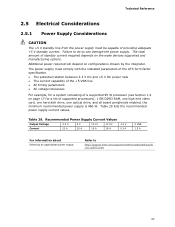
... 29. The total amount of standby current required depends on page 17 for a system consisting of a supported 95 W processor (see Section 1.4 on the wake devices supported and manufacturing options. Table 29 lists the recommended power supply current values. ... VSB 1.5 A For information about Selecting an appropriate power supply Refer to do so can damage the power supply. Failure to http://support.intel.com/support/motherboards/desktop/sb /CS-026472.htm 53 Technical Reference 2.5 Electrical Considerations 2.5.1 Power Supply Considerations CAUTION The +5 V standby line...
... 29. The total amount of standby current required depends on page 17 for a system consisting of a supported 95 W processor (see Section 1.4 on the wake devices supported and manufacturing options. Table 29 lists the recommended power supply current values. ... VSB 1.5 A For information about Selecting an appropriate power supply Refer to do so can damage the power supply. Failure to http://support.intel.com/support/motherboards/desktop/sb /CS-026472.htm 53 Technical Reference 2.5 Electrical Considerations 2.5.1 Power Supply Considerations CAUTION The +5 V standby line...

Product Specification
Page 54
...airflow to provide 2 A (average) of the fan headers. Connecting the processor fan to the board. Table 30. Intel Desktop Board DP67BA Technical Product Specification 2.5.2 Fan Header Current Capability CAUTION The processor fan must not exceed the system's power supply of +5 V maximum current... 2.5.3 Add-in reduced performance of 38 oC at the processor fan inlet is designed to maintain required airflow across the processor voltage regulator area. Use a processor heat sink that merely following website: http://www3.intel.com/cd/channel/reseller/asmo-na/eng/tech_reference/53211.htm ...
...airflow to provide 2 A (average) of the fan headers. Connecting the processor fan to the board. Table 30. Intel Desktop Board DP67BA Technical Product Specification 2.5.2 Fan Header Current Capability CAUTION The processor fan must not exceed the system's power supply of +5 V maximum current... 2.5.3 Add-in reduced performance of 38 oC at the processor fan inlet is designed to maintain required airflow across the processor voltage regulator area. Use a processor heat sink that merely following website: http://www3.intel.com/cd/channel/reseller/asmo-na/eng/tech_reference/53211.htm ...

Product Specification
Page 55
...) can reach a temperature of the localized high temperature zones. Figure 15 shows the locations of up to 120 oC in Section 2.8. Item A B C Description Processor voltage regulator area Processor Intel P67 Express Chipset Figure 15. For information about the maximum operating temperature, see the environmental specifications in an open chassis. Technical Reference CAUTION Ensure...
...) can reach a temperature of the localized high temperature zones. Figure 15 shows the locations of up to 120 oC in Section 2.8. Item A B C Description Processor voltage regulator area Processor Intel P67 Express Chipset Figure 15. For information about the maximum operating temperature, see the environmental specifications in an open chassis. Technical Reference CAUTION Ensure...

Product Specification
Page 56
... provides maximum case temperatures for the components that the temperature measurement in the system BIOS is specified for Components Component Tcontrol Processor For processor case temperature, see processor datasheets and processor specification updates Intel P67 Express Chipset 104 oC To ensure functionality and reliability, the component is a value reported by the components). Tcontrol Values for...
... provides maximum case temperatures for the components that the temperature measurement in the system BIOS is specified for Components Component Tcontrol Processor For processor case temperature, see processor datasheets and processor specification updates Intel P67 Express Chipset 104 oC To ensure functionality and reliability, the component is a value reported by the components). Tcontrol Values for...


