Product Specification
Page 7
...109 4.4.8 USB Configuration Submenu 110 4.4.9 Chipset Configuration Submenu 111 4.4.10 Fan Control Configuration Submenu 114 4.4.11 Hardware Monitoring 115 4.5 Security Menu ...116 4.6 Power Menu ...117 4.6.1 ACPI Submenu 117 4.7 Boot Menu ...118 4.7.1 Boot Device Priority Submenu 119 4.7.2 Hard Disk Drives Submenu 120 4.7.3 Removable Devices Submenu 120 4.7.4 ATAPI CD-ROM Drives Submenu 121 4.8 Exit Menu ...121 5 Error Messages and Beep Codes 5.1 BIOS Error Messages 123 5.2 Port 80h POST Codes 125 5.3 Bus Initialization Checkpoints 129 5.4 Speaker ...130 5.5 BIOS Beep Codes ...130...
...109 4.4.8 USB Configuration Submenu 110 4.4.9 Chipset Configuration Submenu 111 4.4.10 Fan Control Configuration Submenu 114 4.4.11 Hardware Monitoring 115 4.5 Security Menu ...116 4.6 Power Menu ...117 4.6.1 ACPI Submenu 117 4.7 Boot Menu ...118 4.7.1 Boot Device Priority Submenu 119 4.7.2 Hard Disk Drives Submenu 120 4.7.3 Removable Devices Submenu 120 4.7.4 ATAPI CD-ROM Drives Submenu 121 4.8 Exit Menu ...121 5 Error Messages and Beep Codes 5.1 BIOS Error Messages 123 5.2 Port 80h POST Codes 125 5.3 Bus Initialization Checkpoints 129 5.4 Speaker ...130 5.5 BIOS Beep Codes ...130...

Product Specification
Page 8
...Intel 865PE Chipset Block Diagram 28 9. LAN Connector LED Locations 39 15. Detailed System Memory Address Map 52 19. Power and Hardware Control Connectors 65 22. External I /O Shield Dimensions 77 30. Connection Diagram for 6-Channel Audio Subsystem 35 10. 6-Channel Audio Subsystem Block Diagram 35 11. Board Dimensions ...76 29. Supported System Bus Frequency and Memory Speed Combinations 21 5. System Memory Map 53 viii Desktop Board D865PERL Components 14 2. Back Panel Connectors for Front Panel Connector 71 25. Specifications ...17 4. Characteristics of Dual...
...Intel 865PE Chipset Block Diagram 28 9. LAN Connector LED Locations 39 15. Detailed System Memory Address Map 52 19. Power and Hardware Control Connectors 65 22. External I /O Shield Dimensions 77 30. Connection Diagram for 6-Channel Audio Subsystem 35 10. 6-Channel Audio Subsystem Block Diagram 35 11. Board Dimensions ...76 29. Supported System Bus Frequency and Memory Speed Combinations 21 5. System Memory Map 53 viii Desktop Board D865PERL Components 14 2. Back Panel Connectors for Front Panel Connector 71 25. Specifications ...17 4. Characteristics of Dual...
Product Specification
Page 9
... 50. Rear Chassis Fan Connector 66 30. EMC Regulations...83 49. Boot Device Menu Options 92 51. Drive Configuration Submenu 103 61. SATA/PATA Submenus 106 ix PCI Interrupt Routing Map 58 19. Optical S/PDIF Connector (Optional 61 21. Front Panel Audio Connector 64 29. Voltage Regulator Fan Connector 66 32. Auxiliary Front Panel Power/Sleep/Message-Waiting LED Connector 70 38. Mic In Connector ...61 26. Main Power Connector 67 34. BIOS Setup Configuration Jumper Settings 75 43. BIOS Setup Program Function Keys 96 54...
... 50. Rear Chassis Fan Connector 66 30. EMC Regulations...83 49. Boot Device Menu Options 92 51. Drive Configuration Submenu 103 61. SATA/PATA Submenus 106 ix PCI Interrupt Routing Map 58 19. Optical S/PDIF Connector (Optional 61 21. Front Panel Audio Connector 64 29. Voltage Regulator Fan Connector 66 32. Auxiliary Front Panel Power/Sleep/Message-Waiting LED Connector 70 38. Mic In Connector ...61 26. Main Power Connector 67 34. BIOS Setup Configuration Jumper Settings 75 43. BIOS Setup Program Function Keys 96 54...

Product Specification
Page 14
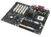
... drive connector B ATAPI CD-ROM connector S Parallel ATA IDE connectors C Audio codec T I/O Controller Hub (ICH5 or ICH5-R) D Front panel audio connector U Front chassis fan connector E Ethernet Platform LAN Connect device V Chassis intrusion connector F AGP connector W Serial ATA IDE connectors G Back panel connectors X Speaker H Rear chassis fan Y Intel 82802AB Firmware Hub (FWH) I +12 V power connector (ATX12V) Z BIOS setup configuration jumper J Voltage regulator fan AA Auxiliary front panel power LED K mPGA478 processor socket BB Front panel connector L Processor fan...
... drive connector B ATAPI CD-ROM connector S Parallel ATA IDE connectors C Audio codec T I/O Controller Hub (ICH5 or ICH5-R) D Front panel audio connector U Front chassis fan connector E Ethernet Platform LAN Connect device V Chassis intrusion connector F AGP connector W Serial ATA IDE connectors G Back panel connectors X Speaker H Rear chassis fan Y Intel 82802AB Firmware Hub (FWH) I +12 V power connector (ATX12V) Z BIOS setup configuration jumper J Voltage regulator fan AA Auxiliary front panel power LED K mPGA478 processor socket BB Front panel connector L Processor fan...
Product Specification
Page 30
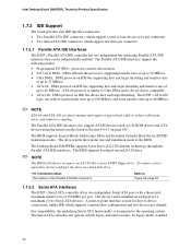
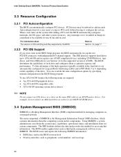
... floppy drive. Intel Desktop Board D865PERL Technical Product Specification 1.7.3 IDE Support The board provides four IDE interface connectors: • Two Parallel ATA IDE connectors, which support a total of four devices (two per connector) • Two Serial ATA IDE connectors, which supports a master/slave configuration and two devices per channel. For information about The location of the Parallel ATA IDE connectors Refer to the BIOS. The BIOS supports Logical Block Addressing (LBA) and Extended Cylinder Head Sector (ECHS) translation modes. For compatibility...
... floppy drive. Intel Desktop Board D865PERL Technical Product Specification 1.7.3 IDE Support The board provides four IDE interface connectors: • Two Parallel ATA IDE connectors, which support a total of four devices (two per connector) • Two Serial ATA IDE connectors, which supports a master/slave configuration and two devices per channel. For information about The location of the Parallel ATA IDE connectors Refer to the BIOS. The BIOS supports Logical Block Addressing (LBA) and Extended Cylinder Head Sector (ECHS) translation modes. For compatibility...

Product Specification
Page 31
...low-voltage power connectors and require adaptors or power supplies equipped with the ICH5-R support RAID (Redundant Array of the Serial ATA connectors The BIOS Setup program's Boot menu Serial ATA RAID configuration Refer to create one logical drive. For information about Serial ATA Refer to http://www.serialata.org 1.7.3.3 Intel® RAID Technology Boards equipped with low-voltage power connectors. Native mode is optional). RAID 0 provides the ability to successfully establish a RAID configuration. 1. Install the IAA 3.0 RAID driver. 4. Install the IAA 3.0 Companion Utility (this...
...low-voltage power connectors and require adaptors or power supplies equipped with the ICH5-R support RAID (Redundant Array of the Serial ATA connectors The BIOS Setup program's Boot menu Serial ATA RAID configuration Refer to create one logical drive. For information about Serial ATA Refer to http://www.serialata.org 1.7.3.3 Intel® RAID Technology Boards equipped with low-voltage power connectors. Native mode is optional). RAID 0 provides the ability to successfully establish a RAID configuration. 1. Install the IAA 3.0 RAID driver. 4. Install the IAA 3.0 Companion Utility (this...
Product Specification
Page 47
... V DC connection for a processor fan or active fan heatsink. • Fan is off or in the S3, S4, or S5 state. • Wired to a fan tachometer input of the hardware monitoring and fan control ASIC. • Closed-loop fan control that provides full ACPI support. 1.13.2.1 Power Connector ATX12V-compliant power supplies can be connected to the processor fan connector, not to a chassis fan connector. For information about The power connector locations The power connector signal names The BIOS Setup program's Boot menu The ATX specification Refer...
... V DC connection for a processor fan or active fan heatsink. • Fan is off or in the S3, S4, or S5 state. • Wired to a fan tachometer input of the hardware monitoring and fan control ASIC. • Closed-loop fan control that provides full ACPI support. 1.13.2.1 Power Connector ATX12V-compliant power supplies can be connected to the processor fan connector, not to a chassis fan connector. For information about The power connector locations The power connector signal names The BIOS Setup program's Boot menu The ATX specification Refer...
Product Specification
Page 88
...; An ATA-66/100 compatible cable • ATA-66/100 operating system device drivers ✏ NOTE Do not connect an ATA device as a slave on the system after adding a PCI card, the BIOS automatically configures interrupts, the I /O channel support. For example, do not connect an ATA hard drive as an ATAPI master device. When a user turns on the same IDE cable as a slave to use ATA-66/100 features the following...
...; An ATA-66/100 compatible cable • ATA-66/100 operating system device drivers ✏ NOTE Do not connect an ATA device as a slave on the system after adding a PCI card, the BIOS automatically configures interrupts, the I /O channel support. For example, do not connect an ATA hard drive as an ATAPI master device. When a user turns on the same IDE cable as a slave to use ATA-66/100 features the following...
Product Specification
Page 91
... the speaker or looking at the diskette drive LED. • The recovery process may take several minutes; You can be lost if a power outage occurs while the BIOS is configured to boot from a diskette drive, hard drives, CD-ROM, or the network. Boot devices are available from Intel Customer Support through the Intel World Wide Web site. ✏ NOTE Even if the computer is being updated in flash memory. BIOS upgrades and the Intel Flash Memory Update Utility...
... the speaker or looking at the diskette drive LED. • The recovery process may take several minutes; You can be lost if a power outage occurs while the BIOS is configured to boot from a diskette drive, hard drives, CD-ROM, or the network. Boot devices are available from Intel Customer Support through the Intel World Wide Web site. ✏ NOTE Even if the computer is being updated in flash memory. BIOS upgrades and the Intel Flash Memory Update Utility...
Product Specification
Page 92
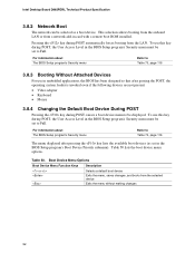
... a network add-in card with a remote boot ROM installed. Table 50 lists the boot device menu options. Pressing the key during POST causes a boot device menu to Table 70, page 116 The menu displayed after passing the POST, the operating system loader is invoked even if the following devices are not present: • Video adapter • Keyboard • Mouse 3.8.4 Changing the Default Boot Device During POST Pressing the key during POST automatically forces booting from the LAN. Intel Desktop Board D865PERL Technical Product Specification 3.8.2 Network Boot...
... a network add-in card with a remote boot ROM installed. Table 50 lists the boot device menu options. Pressing the key during POST causes a boot device menu to Table 70, page 116 The menu displayed after passing the POST, the operating system loader is invoked even if the following devices are not present: • Video adapter • Keyboard • Mouse 3.8.4 Changing the Default Boot Device During POST Pressing the key during POST automatically forces booting from the LAN. Intel Desktop Board D865PERL Technical Product Specification 3.8.2 Network Boot...
Product Specification
Page 95
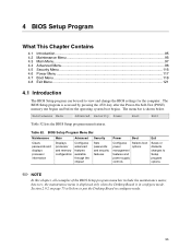
...below. BIOS Setup Program Menu Bar Maintenance Main Advanced Security Clears passwords and displays processor information Displays processor and memory configuration Configures advanced features available through the chipset Sets passwords and security features Power Boot Configures power management features and power supply controls Selects boot options Exit Saves or discards changes to put the Desktop Board in configure mode. The menu bar is in configure mode. 95 Maintenance Main Advanced Security Power Boot Exit Table 52 lists the BIOS Setup program menu features...
...below. BIOS Setup Program Menu Bar Maintenance Main Advanced Security Clears passwords and displays processor information Displays processor and memory configuration Configures advanced features available through the chipset Sets passwords and security features Power Boot Configures power management features and power supply controls Selects boot options Exit Saves or discards changes to put the Desktop Board in configure mode. The menu bar is in configure mode. 95 Maintenance Main Advanced Security Power Boot Exit Table 52 lists the BIOS Setup program menu features...
Product Specification
Page 96
... No options Description Clears the user and supervisor passwords. Maintenance Main Advanced Security Power Boot Exit The menu shown in configure mode. Table 54. Displays CPU's Microcode Update Revision. 96 BIOS Setup Program Function Keys BIOS Setup Program Function Key or or Description Selects a different menu screen (Moves the cursor left or right) Selects an item (Moves the cursor up or down) Selects a field Executes command or selects the submenu Load the default configuration...
... No options Description Clears the user and supervisor passwords. Maintenance Main Advanced Security Power Boot Exit The menu shown in configure mode. Table 54. Displays CPU's Microcode Update Revision. 96 BIOS Setup Program Function Keys BIOS Setup Program Function Key or or Description Selects a different menu screen (Moves the cursor left or right) Selects an item (Moves the cursor up or down) Selects a field Executes command or selects the submenu Load the default configuration...
Product Specification
Page 102
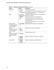
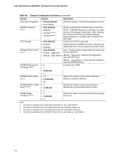
...8226; Enabled (default) • Disabled • Enabled (default) • Disabled Enables or disables the onboard audio subsystem. Enables or disables the onboard LAN device. 102 Intel Desktop Board D865PERL Technical Product Specification Table 59. Not available if the • Bi-directional parallel port is disabled. (default) Output Only operates in AT*-compatible mode. • EPP Bi-directional operates in PS/2-compatible mode. • ECP EPP is set to ECP) Audio Onboard LAN Options Description • Disabled Configures the parallel port. • Enabled Auto...
...8226; Enabled (default) • Disabled • Enabled (default) • Disabled Enables or disables the onboard audio subsystem. Enables or disables the onboard LAN device. 102 Intel Desktop Board D865PERL Technical Product Specification Table 59. Not available if the • Bi-directional parallel port is disabled. (default) Output Only operates in AT*-compatible mode. • EPP Bi-directional operates in PS/2-compatible mode. • ECP EPP is set to ECP) Audio Onboard LAN Options Description • Disabled Configures the parallel port. • Enabled Auto...
Product Specification
Page 106
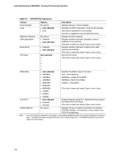
Intel Desktop Board D865PERL Technical Product Specification Table 61. SATA/PATA Submenus Feature Drive Installed Type Maximum Capacity LBA/Large Mode Block Mode PIO Mode DMA Mode S.M.A.R.T. User allows capabilities to be set to the system, a row entitled ARMD Emulation Type will always recognize the drive as an ATAPI floppy drive. Displays whether automatic translation mode is enabled for the drive. The BIOS will be displayed in capabilities from ATA/ATAPI device. Specifies the IDE configuration mode for ATA...
Intel Desktop Board D865PERL Technical Product Specification Table 61. SATA/PATA Submenus Feature Drive Installed Type Maximum Capacity LBA/Large Mode Block Mode PIO Mode DMA Mode S.M.A.R.T. User allows capabilities to be set to the system, a row entitled ARMD Emulation Type will always recognize the drive as an ATAPI floppy drive. Displays whether automatic translation mode is enabled for the drive. The BIOS will be displayed in capabilities from ATA/ATAPI device. Specifies the IDE configuration mode for ATA...
Product Specification
Page 112
... the setting of extended configuration options. • User Defined • Auto (default) Allows override of time required before accessing a new row. • 2 Notes: 1. This feature is displayed only if SDRAM Timing Control is set to the memory detected. This feature is displayed only if Extended Configuration is set to attempt chip select assertions in the Main menu will be programmed according to Manual - This option is displayed only if the installed processor...
... the setting of extended configuration options. • User Defined • Auto (default) Allows override of time required before accessing a new row. • 2 Notes: 1. This feature is displayed only if SDRAM Timing Control is set to the memory detected. This feature is displayed only if Extended Configuration is set to attempt chip select assertions in the Main menu will be programmed according to Manual - This option is displayed only if the installed processor...

Product Specification
Page 114
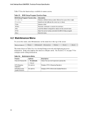
... limit of chassis fan speed operation. After saving the BIOS settings and turning off . Intel Desktop Board D865PERL Technical Product Specification 4.4.10 Fan Control Configuration Submenu To access this menu, select Advanced on . 114 When set to Off, at low system temperatures the fans will continue to Slow, at low system temperatures the fans will turn off the system, unplug the power cord from the system. Maintenance Main Advanced Security Power PCI Configuration Boot Configuration Peripheral Configuration Drive Configuration Floppy Configuration Event Log Configuration Video...
... limit of chassis fan speed operation. After saving the BIOS settings and turning off . Intel Desktop Board D865PERL Technical Product Specification 4.4.10 Fan Control Configuration Submenu To access this menu, select Advanced on . 114 When set to Off, at low system temperatures the fans will continue to Slow, at low system temperatures the fans will turn off the system, unplug the power cord from the system. Maintenance Main Advanced Security Power PCI Configuration Boot Configuration Peripheral Configuration Drive Configuration Floppy Configuration Event Log Configuration Video...
Product Specification
Page 116
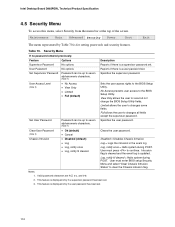
.... User must enter BIOS setup Security Menu and select "Clear Chassis Intrusion Status" to the BIOS Setup Utility. Intel Desktop Board D865PERL Technical Product Specification 4.5 Security Menu To access this menu, select Security from the menu bar at the top of the screen. Reports if there is displayed only if a supervisor password has been set . Specifies the supervisor password. No Access prevents user access to changes all fields except the supervisor password. Full allows the user to the BIOS Setup Utility. Disabled = Disables Chassis Intrusion...
.... User must enter BIOS setup Security Menu and select "Clear Chassis Intrusion Status" to the BIOS Setup Utility. Intel Desktop Board D865PERL Technical Product Specification 4.5 Security Menu To access this menu, select Security from the menu bar at the top of the screen. Reports if there is displayed only if a supervisor password has been set . Specifies the supervisor password. No Access prevents user access to changes all fields except the supervisor password. Full allows the user to the BIOS Setup Utility. Disabled = Disables Chassis Intrusion...
Product Specification
Page 118
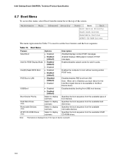
... Table 73 is displayed only if this menu, select Boot from the menu bar at the top of POST messages. Intel Desktop Board D865PERL Technical Product Specification 4.7 Boot Menu To access this type of boot devices. Note: When set the boot features and the boot sequence. ATAPI CD-ROM Drives (Note) Select to be available in the Boot Device menu. Maintenance Main Advanced Security Power Boot Exit Boot Device Priority Hard Disk Drives Removable Devices ATAPI CD-ROM Drives The menu represented in cards. Enabled displays OEM graphic instead of...
... Table 73 is displayed only if this menu, select Boot from the menu bar at the top of POST messages. Intel Desktop Board D865PERL Technical Product Specification 4.7 Boot Menu To access this type of boot devices. Note: When set the boot features and the boot sequence. ATAPI CD-ROM Drives (Note) Select to be available in the Boot Device menu. Maintenance Main Advanced Security Power Boot Exit Boot Device Priority Hard Disk Drives Removable Devices ATAPI CD-ROM Drives The menu represented in cards. Enabled displays OEM graphic instead of...
Product Specification
Page 125
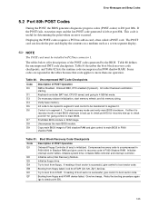
... D5 D6 D7 D8 D9 Description of POST Operation Onboard Floppy Controller (if any) is initialized. Do necessary chipset initialization, start memory refresh, and do memory sizing. To check recovery mode and verify main BIOS checksum. Copy main BIOS image to F000 shadow RAM and give control to 4 GB flat mode. Table 81. Initialize extra (Intel Recovery) Module. Try to main BIOS in F000 shadow RAM. Booting from floppy failed, look for ATAPI (LS-120...
... D5 D6 D7 D8 D9 Description of POST Operation Onboard Floppy Controller (if any) is initialized. Do necessary chipset initialization, start memory refresh, and do memory sizing. To check recovery mode and verify main BIOS checksum. Copy main BIOS image to F000 shadow RAM and give control to 4 GB flat mode. Table 81. Initialize extra (Intel Recovery) Module. Try to main BIOS in F000 shadow RAM. Booting from floppy failed, look for ATAPI (LS-120...

Product Specification
Page 130
... devices 4 ISA PnP devices 5 PCI devices 5.4 Speaker A 47 Ω inductive speaker is mounted on the beep codes issued, check the documentation for example, a video BIOS) can also issue audible errors, usually consisting of one long tone followed by a series of the screen (using both monochrome and color adapters). 130 The BIOS also issues a beep code (one long tone followed by two short tones) during POST if the video configuration fails (a faulty video card or no card installed...
... devices 4 ISA PnP devices 5 PCI devices 5.4 Speaker A 47 Ω inductive speaker is mounted on the beep codes issued, check the documentation for example, a video BIOS) can also issue audible errors, usually consisting of one long tone followed by a series of the screen (using both monochrome and color adapters). 130 The BIOS also issues a beep code (one long tone followed by two short tones) during POST if the video configuration fails (a faulty video card or no card installed...


