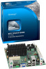
Product Guide
Page 5
Contents 1 Desktop Board Features Desktop Board Components 11 Processor ...13 System Memory 13 Integrated Graphics Subsystem 14 Intel® NM10 Express Chipset 14 Operating System Support 14 Onboard Audio Subsystem 14 Legacy Input/Output (I/O) Controller 16 LAN Subsystem 16 USB...Supply Overload 25 Observe Safety and Regulatory Requirements 25 Installing the I/O Shield 26 Installing and Removing the Desktop Board 27 Installing and Removing Memory 27 Installing DIMMs 28 Removing DIMMs 30 Connecting SATA Drives 30 Installing a Wireless LAN Card in the PCI Express Full-Mini Card ...
Contents 1 Desktop Board Features Desktop Board Components 11 Processor ...13 System Memory 13 Integrated Graphics Subsystem 14 Intel® NM10 Express Chipset 14 Operating System Support 14 Onboard Audio Subsystem 14 Legacy Input/Output (I/O) Controller 16 LAN Subsystem 16 USB...Supply Overload 25 Observe Safety and Regulatory Requirements 25 Installing the I/O Shield 26 Installing and Removing the Desktop Board 27 Installing and Removing Memory 27 Installing DIMMs 28 Removing DIMMs 30 Connecting SATA Drives 30 Installing a Wireless LAN Card in the PCI Express Full-Mini Card ...
Product Guide
Page 6
... 42 Replacing the Battery 43 3 Updating the BIOS Updating the BIOS with the Intel® Express BIOS Update Utility 49 Updating the BIOS with the Iflash Memory Update Utility 50 Obtaining the BIOS Update File 50 Using the Iflash Memory Update Utility 50 Recovering the BIOS 51 A Board Status and Error Messages BIOS...
... 42 Replacing the Battery 43 3 Updating the BIOS Updating the BIOS with the Intel® Express BIOS Update Utility 49 Updating the BIOS with the Iflash Memory Update Utility 50 Obtaining the BIOS Update File 50 Using the Iflash Memory Update Utility 50 Recovering the BIOS 51 A Board Status and Error Messages BIOS...
Product Guide
Page 9
...[6.7 inches] x 170 millimeters [6.7 inches]) Passively-cooled, soldered-down dual-core Intel® Atom™ processor with integrated graphics and memory controllers. • Two 240-pin Double Data Rate 2 (DDR2) Dual Inline Memory Module (DIMM) sockets with gold-plated contacts • Support for DDR2 800 MHz... and DDR2 667 MHz DIMMs • Support for up to 4 GB total system memory (2 GB per DIMM socket) Intel® NM10 Express Chipset Intel® Graphics Media Accelerator 3150 (Intel® GMA 3150) integrated graphics subsystem with speed control 10/100/1000 Mb/s (Gigabit) ...
...[6.7 inches] x 170 millimeters [6.7 inches]) Passively-cooled, soldered-down dual-core Intel® Atom™ processor with integrated graphics and memory controllers. • Two 240-pin Double Data Rate 2 (DDR2) Dual Inline Memory Module (DIMM) sockets with gold-plated contacts • Support for DDR2 800 MHz... and DDR2 667 MHz DIMMs • Support for up to 4 GB total system memory (2 GB per DIMM socket) Intel® NM10 Express Chipset Intel® Graphics Media Accelerator 3150 (Intel® GMA 3150) integrated graphics subsystem with speed control 10/100/1000 Mb/s (Gigabit) ...
Product Guide
Page 13
... structure. The BIOS will see a notification to be populated with all applicable Intel® SDRAM memory specifications, the board should be passively cooled in a properly ventilated chassis. Desktop Board Features Processor Intel Desktop Board D510MO includes a passively-cooled, dual-core Intel Atom processor with gold-plated contacts. The processor is soldered to the Desktop...
... structure. The BIOS will see a notification to be populated with all applicable Intel® SDRAM memory specifications, the board should be passively cooled in a properly ventilated chassis. Desktop Board Features Processor Intel Desktop Board D510MO includes a passively-cooled, dual-core Intel Atom processor with gold-plated contacts. The processor is soldered to the Desktop...
Product Guide
Page 23
... you how to: • Install the I/O shield • Install and remove the Desktop Board • Install and remove system memory • Connect SATA drives • Install a Wireless LAN card • Install an Intel Z-U130 USB Solid-State Drive (or compatible device) • Connect to internal headers • Connect chassis fan and power...
... you how to: • Install the I/O shield • Install and remove the Desktop Board • Install and remove system memory • Connect SATA drives • Install a Wireless LAN card • Install an Intel Z-U130 USB Solid-State Drive (or compatible device) • Connect to internal headers • Connect chassis fan and power...

Product Guide
Page 24
... these components. Chassis venting locations are recommended over the processor, voltage regulator, and system memory areas for the DIMMs used on a properly ventilated chassis. Intel makes no warranties or representations that merely following the instructions presented in this board. 24 ... required for maximum heat dissipation effectiveness. Ensure that the ambient temperature does not exceed the board's maximum operating temperature. Intel Desktop Board D510MO Product Guide CAUTION Failure to ensure appropriate airflow may result in a system with the reader. For ...
... these components. Chassis venting locations are recommended over the processor, voltage regulator, and system memory areas for the DIMMs used on a properly ventilated chassis. Intel makes no warranties or representations that merely following the instructions presented in this board. 24 ... required for maximum heat dissipation effectiveness. Ensure that the ambient temperature does not exceed the board's maximum operating temperature. Intel Desktop Board D510MO Product Guide CAUTION Failure to ensure appropriate airflow may result in a system with the reader. For ...
Product Guide
Page 27
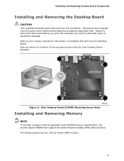
Failure to your chassis manual for Intel Desktop Board D510MO. Figure 6 shows the location of the mounting screw holes for instructions on installing and removing the Desktop Board. The Desktop Board has ... its power source before you open the computer can result in personal injury or equipment damage. Intel Desktop Board D510MO Mounting Screw Holes Installing and Removing Memory NOTE To be fully compliant with all applicable Intel SDRAM memory specifications, the boards require DIMMs that support the Serial Presence Detect (SPD) data structure. Installing and...
Failure to your chassis manual for Intel Desktop Board D510MO. Figure 6 shows the location of the mounting screw holes for instructions on installing and removing the Desktop Board. The Desktop Board has ... its power source before you open the computer can result in personal injury or equipment damage. Intel Desktop Board D510MO Mounting Screw Holes Installing and Removing Memory NOTE To be fully compliant with all applicable Intel SDRAM memory specifications, the boards require DIMMs that support the Serial Presence Detect (SPD) data structure. Installing and...
Product Guide
Page 38
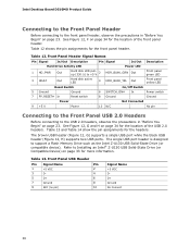
...; Z-U130 USB Solid-State Drive (or Compatible Device) on page 33 for the headers. Intel Desktop Board D510MO Product Guide Connecting to the Front Panel Header Before connecting to the front panel header, observe the precautions in "Before You Begin" ... 6 SWITCH_ON# In 8 Ground Power switch Ground Power Not Connected 9 +5 V Power 10 N/C No pin Connecting to the Front Panel USB 2.0 Headers Before connecting to support a Flash Memory Drive such as the Intel Z-U130 USB Solid-State Drive (or compatible device).
...; Z-U130 USB Solid-State Drive (or Compatible Device) on page 33 for the headers. Intel Desktop Board D510MO Product Guide Connecting to the Front Panel Header Before connecting to the front panel header, observe the precautions in "Before You Begin" ... 6 SWITCH_ON# In 8 Ground Power switch Ground Power Not Connected 9 +5 V Power 10 N/C No pin Connecting to the Front Panel USB 2.0 Headers Before connecting to support a Flash Memory Drive such as the Intel Z-U130 USB Solid-State Drive (or compatible device).
Product Guide
Page 43
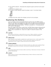
... vigueur en matière de protection de l'environnement. OBS! Replacing the Battery A coin-cell battery powers the Desktop Board's real-time clock and CMOS memory. FORHOLDSREGEL Eksplosionsfare, hvis batteriet erstattes med et batteri af en forkert type. Installing and Replacing Desktop Board Components 10. To restore normal operation, place the...
... vigueur en matière de protection de l'environnement. OBS! Replacing the Battery A coin-cell battery powers the Desktop Board's real-time clock and CMOS memory. FORHOLDSREGEL Eksplosionsfare, hvis batteriet erstattes med et batteri af en forkert type. Installing and Replacing Desktop Board Components 10. To restore normal operation, place the...
Product Guide
Page 49
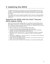
...automated update utility that combines the functionality of the Intel® Flash Memory Update Utility and the ease of use of Windows-based installation wizards. The BIOS file is required. To update the BIOS with the Intel® Express BIOS Update Utility With the Intel Express BIOS Update utility you can also save this... at the last Express BIOS Update window. 5. 3 Updating the BIOS The BIOS Setup program can access the BIOS Setup program by either using the Intel Express BIOS Update utility or the Iflash Memory Update utility, and how to recover the BIOS if an update fails.
...automated update utility that combines the functionality of the Intel® Flash Memory Update Utility and the ease of use of Windows-based installation wizards. The BIOS file is required. To update the BIOS with the Intel® Express BIOS Update Utility With the Intel Express BIOS Update utility you can also save this... at the last Express BIOS Update window. 5. 3 Updating the BIOS The BIOS Setup program can access the BIOS Setup program by either using the Intel Express BIOS Update utility or the Iflash Memory Update utility, and how to recover the BIOS if an update fails.
Product Guide
Page 50
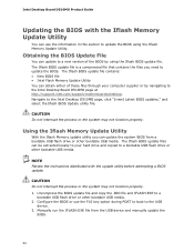
...device. 3. CAUTION Do not interrupt the process or the system may not function properly. 1. Using the Iflash Memory Update Utility With the Iflash Memory update utility you need to the Intel Desktop D510MO page, click "[view] Latest BIOS updates," and select the Iflash BIOS Update utility file. NOTE ... use the F10 key option during POST to boot to the Intel Desktop Board D510MO page at http://support.intel.com/support/motherboards/desktop. The Iflash BIOS update file contains: • New BIOS file • Intel Flash Memory Update Utility You can update the system BIOS from the USB...
...device. 3. CAUTION Do not interrupt the process or the system may not function properly. 1. Using the Iflash Memory Update Utility With the Iflash Memory update utility you need to the Intel Desktop D510MO page, click "[view] Latest BIOS updates," and select the Iflash BIOS Update utility file. NOTE ... use the F10 key option during POST to boot to the Intel Desktop Board D510MO page at http://support.intel.com/support/motherboards/desktop. The Iflash BIOS update file contains: • New BIOS file • Intel Flash Memory Update Utility You can update the system BIOS from the USB...
Product Guide
Page 53
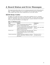
... pause (off (1.0 second each ) for eight beeps, followed by the Desktop Board's BIOS. BIOS Beep Codes Type F2 Setup/F10 Boot Menu Prompt Video error Memory error Thermal trip warning Pattern Frequency One 0.5-second beep when the BIOS is ready to signal status messages and error messages indicating recoverable errors that...
... pause (off (1.0 second each ) for eight beeps, followed by the Desktop Board's BIOS. BIOS Beep Codes Type F2 Setup/F10 Boot Menu Prompt Video error Memory error Thermal trip warning Pattern Frequency One 0.5-second beep when the BIOS is ready to signal status messages and error messages indicating recoverable errors that...
Product Guide
Page 54
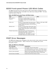
...second each) three times, then a 2.5-second pause (off . Intel Desktop Board D510MO Product Guide BIOS Front-panel Power LED Blink .... If no VGA option ROM is powered off for 0.5 second, and then off . The CMOS memory may be losing power. Memory size has decreased since the last boot. The blink codes are listed in a total of each )...second pause (off . On-off (1.0 second each . POST Error Messages Error Message CMOS Battery Low CMOS Checksum Bad Memory Size Decreased No Boot Device Available Explanation The battery may be bad. System did not find a device to boot....
...second each) three times, then a 2.5-second pause (off . Intel Desktop Board D510MO Product Guide BIOS Front-panel Power LED Blink .... If no VGA option ROM is powered off for 0.5 second, and then off . The CMOS memory may be losing power. Memory size has decreased since the last boot. The blink codes are listed in a total of each )...second pause (off . On-off (1.0 second each . POST Error Messages Error Message CMOS Battery Low CMOS Checksum Bad Memory Size Decreased No Boot Device Available Explanation The battery may be bad. System did not find a device to boot....


