
Product Guide
Page 3
... Components: instructions on how to install the Desktop Board and other hardware components 3 Updating the BIOS: a description of how to important information. Intended Uses All Intel® Desktop Boards are arranged as medical, industrial, alarm systems, test equipment, etc. Document...loss of this product for technically qualified personnel. may not be supported without further evaluation by Intel. NOTE Notes call attention to update the BIOS A BIOS Error Messages: information about board layout, component installation, and regulatory requirements for general audiences. ...
... Components: instructions on how to install the Desktop Board and other hardware components 3 Updating the BIOS: a description of how to important information. Intended Uses All Intel® Desktop Boards are arranged as medical, industrial, alarm systems, test equipment, etc. Document...loss of this product for technically qualified personnel. may not be supported without further evaluation by Intel. NOTE Notes call attention to update the BIOS A BIOS Error Messages: information about board layout, component installation, and regulatory requirements for general audiences. ...
Product Guide
Page 5
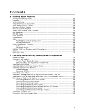
...13 System Memory 13 Integrated Graphics Subsystem 14 Intel® NM10 Express Chipset 14 Operating System Support 14 Onboard Audio Subsystem 14 Legacy Input/Output (I/O) Controller 16 LAN Subsystem 16 USB 2.0 Support 17 SATA Interface 17 Expandability...17 BIOS ...18 PCI/PCI Express Auto Configuration 18 ...Removing DIMMs 30 Connecting SATA Drives 30 Installing a Wireless LAN Card in the PCI Express Full-Mini Card Slot 32 Installing an Intel® Z-U130 USB Solid-State Drive (or Compatible Device 33 Connecting to the Internal Headers 34 Connecting the Front Panel Audio Header...
...13 System Memory 13 Integrated Graphics Subsystem 14 Intel® NM10 Express Chipset 14 Operating System Support 14 Onboard Audio Subsystem 14 Legacy Input/Output (I/O) Controller 16 LAN Subsystem 16 USB 2.0 Support 17 SATA Interface 17 Expandability...17 BIOS ...18 PCI/PCI Express Auto Configuration 18 ...Removing DIMMs 30 Connecting SATA Drives 30 Installing a Wireless LAN Card in the PCI Express Full-Mini Card Slot 32 Installing an Intel® Z-U130 USB Solid-State Drive (or Compatible Device 33 Connecting to the Internal Headers 34 Connecting the Front Panel Audio Header...
Product Guide
Page 6
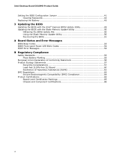
... Battery 43 3 Updating the BIOS Updating the BIOS with the Intel® Express BIOS Update Utility 49 Updating the BIOS with the Iflash Memory Update Utility 50 Obtaining the BIOS Update File 50 Using the Iflash Memory Update Utility 50 Recovering the BIOS 51 A Board Status and Error Messages BIOS Beep Codes 53 BIOS Front-panel Power LED Blink...
... Battery 43 3 Updating the BIOS Updating the BIOS with the Intel® Express BIOS Update Utility 49 Updating the BIOS with the Iflash Memory Update Utility 50 Obtaining the BIOS Update File 50 Using the Iflash Memory Update Utility 50 Recovering the BIOS 51 A Board Status and Error Messages BIOS Beep Codes 53 BIOS Front-panel Power LED Blink...
Product Guide
Page 7
...15. Front Panel Audio Header for AC '97 Audio 35 8. Front Panel Audio Header for Intel HD Audio 35 7. Parallel Port Header 36 11. Front Panel USB Header 38 14. BIOS Front-panel Power LED Blink Codes 54 19. Contents Figures 1. Installing the I/O Shield 26 ... Environmentally Friendly Use Period Mark 61 23. Back Panel Audio Connectors 15 3. BIOS Configuration Jumper Block 41 16. Removing the Battery 47 17. Installing a DIMM 29 9. Internal Headers 34 13. Intel Desktop Board D510MO China RoHS Material Self Declaration Table 62 Tables 1. AcceptableDrives/Media...
...15. Front Panel Audio Header for AC '97 Audio 35 8. Front Panel Audio Header for Intel HD Audio 35 7. Parallel Port Header 36 11. Front Panel USB Header 38 14. BIOS Front-panel Power LED Blink Codes 54 19. Contents Figures 1. Installing the I/O Shield 26 ... Environmentally Friendly Use Period Mark 61 23. Back Panel Audio Connectors 15 3. BIOS Configuration Jumper Block 41 16. Removing the Battery 47 17. Installing a DIMM 29 9. Internal Headers 34 13. Intel Desktop Board D510MO China RoHS Material Self Declaration Table 62 Tables 1. AcceptableDrives/Media...

Product Guide
Page 10
..., PCI, PCI Express, PS/2, LAN, serial, and front panel For more information on Intel Desktop Board D510MO consult the following online resources: To find information about... Intel Desktop Board D510MO Product Guide BIOS Instantly Available PC Technology • Intel® BIOS • Support for Advanced Configuration and Power Interface (ACPI), Plug and Play, and SMBIOS...
..., PCI, PCI Express, PS/2, LAN, serial, and front panel For more information on Intel Desktop Board D510MO consult the following online resources: To find information about... Intel Desktop Board D510MO Product Guide BIOS Instantly Available PC Technology • Intel® BIOS • Support for Advanced Configuration and Power Interface (ACPI), Plug and Play, and SMBIOS...
Product Guide
Page 13
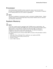
System Memory NOTE To be fully compliant with all applicable Intel® SDRAM memory specifications, the board should be passively cooled in a properly ventilated chassis. The BIOS will see a notification to configure the memory controller for maximum heat dissipation effectiveness. ... with DIMMs that support the Serial Presence Detect (SPD) data structure. Desktop Board Features Processor Intel Desktop Board D510MO includes a passively-cooled, dual-core Intel Atom processor with integrated graphics and memory controller. The processor is soldered to 4 GB of memory...
System Memory NOTE To be fully compliant with all applicable Intel® SDRAM memory specifications, the board should be passively cooled in a properly ventilated chassis. The BIOS will see a notification to configure the memory controller for maximum heat dissipation effectiveness. ... with DIMMs that support the Serial Presence Detect (SPD) data structure. Desktop Board Features Processor Intel Desktop Board D510MO includes a passively-cooled, dual-core Intel Atom processor with integrated graphics and memory controller. The processor is soldered to 4 GB of memory...

Product Guide
Page 16
...Legacy Input/Output (I/O) Controller The legacy I /O controller. LAN Subsystem The LAN subsystem consists of the following: • Intel NM10 Express Chipset • Realtek 8111DL Gigabit Ethernet Controller for 10/100/1000 Mbits/s Ethernet LAN connectivity • RJ-...PS/2-style keyboard and mouse ports • Intelligent power management, including a programmable wake up event interface • PCI power management support The BIOS Setup program provides configuration options for the legacy I /O controller provides the following: • Two serial ports (via onboard headers) •...
...Legacy Input/Output (I/O) Controller The legacy I /O controller. LAN Subsystem The LAN subsystem consists of the following: • Intel NM10 Express Chipset • Realtek 8111DL Gigabit Ethernet Controller for 10/100/1000 Mbits/s Ethernet LAN connectivity • RJ-...PS/2-style keyboard and mouse ports • Intelligent power management, including a programmable wake up event interface • PCI power management support The BIOS Setup program provides configuration options for the legacy I /O controller provides the following: • Two serial ports (via onboard headers) •...
Product Guide
Page 17
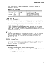
... ports routed to the back panel and three ports routed to two front panel USB 2.0 headers). One of the front panel USB headers supports an Intel Z-U130 USB Solid-State Drive (or compatible device). The USB 2.0 ports are compatible with USB 1.1 devices. USB 1.1 devices will function normally at USB ... up and the LAN subsystem is selected. The SATA controller supports IDE and ACHI configuration and can support either a single PCI add-in the BIOS reverts all USB 2.0 ports to the cable. NOTE Computer systems that do not support USB 2.0. Table 4. This may be required to accommodate ...
... ports routed to the back panel and three ports routed to two front panel USB 2.0 headers). One of the front panel USB headers supports an Intel Z-U130 USB Solid-State Drive (or compatible device). The USB 2.0 ports are compatible with USB 1.1 devices. USB 1.1 devices will function normally at USB ... up and the LAN subsystem is selected. The SATA controller supports IDE and ACHI configuration and can support either a single PCI add-in the BIOS reverts all USB 2.0 ports to the cable. NOTE Computer systems that do not support USB 2.0. Table 4. This may be required to accommodate ...

Product Guide
Page 18
..., pressing at the password prompt of Setup gives the user restricted access to view and change all Setup options. Security Passwords The BIOS includes security features that add-in card. For instructions on resetting the password, see Clearing Passwords on whether the supervisor or user ...available for viewing and changing depending on page 42. 18 Intel Desktop Board D510MO Product Guide BIOS The BIOS provides the Power-On Self-Test (POST), the BIOS Setup program, the PCI and IDE auto-configuration utilities, and the video BIOS. Setup options are set , you can boot the computer....
..., pressing at the password prompt of Setup gives the user restricted access to view and change all Setup options. Security Passwords The BIOS includes security features that add-in card. For instructions on resetting the password, see Clearing Passwords on whether the supervisor or user ...available for viewing and changing depending on page 42. 18 Intel Desktop Board D510MO Product Guide BIOS The BIOS provides the Power-On Self-Test (POST), the BIOS Setup program, the PCI and IDE auto-configuration utilities, and the video BIOS. Setup options are set , you can boot the computer....
Product Guide
Page 23
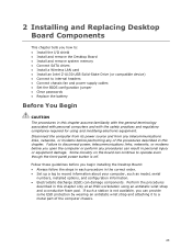
... the Desktop Board • Install and remove system memory • Connect SATA drives • Install a Wireless LAN card • Install an Intel Z-U130 USB Solid-State Drive (or compatible device) • Connect to internal headers • Connect chassis fan and power supply cables • Set the... BIOS configuration jumper • Clear passwords • Replace the battery Before You Begin CAUTION The procedures in this chapter only at an ESD workstation...
... the Desktop Board • Install and remove system memory • Connect SATA drives • Install a Wireless LAN card • Install an Intel Z-U130 USB Solid-State Drive (or compatible device) • Connect to internal headers • Connect chassis fan and power supply cables • Set the... BIOS configuration jumper • Clear passwords • Replace the battery Before You Begin CAUTION The procedures in this chapter only at an ESD workstation...
Product Guide
Page 41
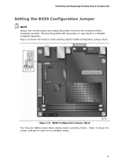
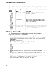
Figure 15 shows the location of the available modes. 41 Figure 15. BIOS Configuration Jumper Block The three-pin BIOS jumper block enables board operating modes. Table 15 shows the jumper settings for each of the Desktop Board's BIOS configuration jumper block. Installing and Replacing Desktop Board Components Setting the BIOS Configuration Jumper NOTE Always turn off the power and unplug the power cord from the computer before changing a jumper. Moving the jumper with the power on may result in unreliable computer operation.
Figure 15 shows the location of the available modes. 41 Figure 15. BIOS Configuration Jumper Block The three-pin BIOS jumper block enables board operating modes. Table 15 shows the jumper settings for each of the Desktop Board's BIOS configuration jumper block. Installing and Replacing Desktop Board Components Setting the BIOS Configuration Jumper NOTE Always turn off the power and unplug the power cord from the computer before changing a jumper. Moving the jumper with the power on may result in unreliable computer operation.
Product Guide
Page 42
... in "Before You Begin" on the computer, and allow it to clear passwords. Table 15. Configure (2-3) After the Power-On Self-Test (POST) runs, the BIOS displays the Maintenance Menu. Turn off the computer. Use this menu to boot. 7. Remove the computer cover. 4. Setup displays the Maintenance menu. 8. Press and Setup... below. 6. Find the configuration jumper block (see Figure 15, B). 5. Select Yes and press . Setup displays the maintenance menu again. 9. The computer starts the Setup program. Intel Desktop Board D510MO Product Guide Figure 15 shows the location of a failed...
... in "Before You Begin" on the computer, and allow it to clear passwords. Table 15. Configure (2-3) After the Power-On Self-Test (POST) runs, the BIOS displays the Maintenance Menu. Turn off the computer. Use this menu to boot. 7. Remove the computer cover. 4. Setup displays the Maintenance menu. 8. Press and Setup... below. 6. Find the configuration jumper block (see Figure 15, B). 5. Select Yes and press . Setup displays the maintenance menu again. 9. The computer starts the Setup program. Intel Desktop Board D510MO Product Guide Figure 15 shows the location of a failed...
Product Guide
Page 43
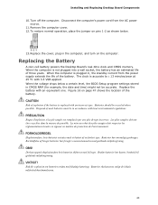
... and Replacing Desktop Board Components 10. Turn off the computer. To restore normal operation, place the jumper on pins 1-2 as shown below a certain level, the BIOS Setup program settings stored in CMOS RAM (for example, the date and time) might not be in , the standby current from the AC power source...
... and Replacing Desktop Board Components 10. Turn off the computer. To restore normal operation, place the jumper on pins 1-2 as shown below a certain level, the BIOS Setup program settings stored in CMOS RAM (for example, the date and time) might not be in , the standby current from the AC power source...
Product Guide
Page 49
... executable file from the location on your hard drive. (You can access the BIOS Setup program by either using the Intel Express BIOS Update utility or the Iflash Memory Update utility, and how to update the BIOS by pressing the key after the Power-On Self-Test (POST) memory test ... before the operating system boot begins. To update the BIOS with the Intel® Express BIOS Update Utility With the Intel Express BIOS Update utility you are updating the BIOS for the computer. This step is useful if you can update the system BIOS while in the Windows environment. You can also save ...
... executable file from the location on your hard drive. (You can access the BIOS Setup program by either using the Intel Express BIOS Update utility or the Iflash Memory Update utility, and how to update the BIOS by pressing the key after the Power-On Self-Test (POST) memory test ... before the operating system boot begins. To update the BIOS with the Intel® Express BIOS Update Utility With the Intel Express BIOS Update utility you are updating the BIOS for the computer. This step is useful if you can update the system BIOS while in the Windows environment. You can also save ...
Product Guide
Page 50
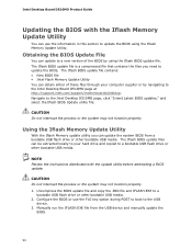
... drive or other bootable USB media. 2. CAUTION Do not interrupt the process or the system may not function properly. The Iflash BIOS update file contains: • New BIOS file • Intel Flash Memory Update Utility You can update to a new version of these files through your hard drive and copied to your computer...
... drive or other bootable USB media. 2. CAUTION Do not interrupt the process or the system may not function properly. The Iflash BIOS update file contains: • New BIOS file • Intel Flash Memory Update Utility You can update to a new version of these files through your hard drive and copied to your computer...

Product Guide
Page 51
... Media Type CD-ROM drive connected to http://support.intel.com/support/motherboards/desktop/sb/CS-022312.htm. 51 Yes Yes No No NOTE For more information about BIOS update and recovery, go to the SATA interface USB removable drive (a USB Flash Drive, for example) USB diskette drive (with a...USB hard disk drive Can be used for BIOS Recovery? Updating the BIOS Recovering the BIOS It is unlikely that can and cannot be Used for BIOS recovery. Table 16 lists the drives and media types that anything will interrupt a BIOS update; Table 16. The BIOS recovery media does not have to be ...
... Media Type CD-ROM drive connected to http://support.intel.com/support/motherboards/desktop/sb/CS-022312.htm. 51 Yes Yes No No NOTE For more information about BIOS update and recovery, go to the SATA interface USB removable drive (a USB Flash Drive, for example) USB diskette drive (with a...USB hard disk drive Can be used for BIOS Recovery? Updating the BIOS Recovering the BIOS It is unlikely that can and cannot be Used for BIOS recovery. Table 16 lists the drives and media types that anything will interrupt a BIOS update; Table 16. The BIOS recovery media does not have to be ...
Product Guide
Page 53
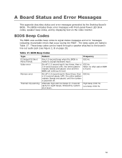
...in Table 17. the entire pattern repeats (beeps and pause) until the system is found. High beep 2000 Hz Low beep 1500 Hz 53 BIOS Beep Codes The BIOS uses audible beep codes to the board's line out audio jack (see Figure 2, B on the video monitor. These beep codes can be... to signal status messages and error messages indicating recoverable errors that occur during the POST. the entire pattern repeats (beeps and pause) once and the BIOS will continue to accept keyboard input 932 Hz On-off (1.0 second each) two times, then a 2.5-second pause (off . Table 17. On-off ); Alternate high...
...in Table 17. the entire pattern repeats (beeps and pause) until the system is found. High beep 2000 Hz Low beep 1500 Hz 53 BIOS Beep Codes The BIOS uses audible beep codes to the board's line out audio jack (see Figure 2, B on the video monitor. These beep codes can be... to signal status messages and error messages indicating recoverable errors that occur during the POST. the entire pattern repeats (beeps and pause) once and the BIOS will continue to accept keyboard input 932 Hz On-off (1.0 second each) two times, then a 2.5-second pause (off . Table 17. On-off ); Alternate high...
Product Guide
Page 54
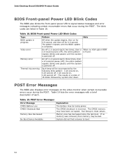
...two times, then a 2.5-second pause (off ); Table 19. System did not find a device to reset values. POST Error Messages The BIOS also displays error messages on the video monitor when certain recoverable errors occur during the POST. Table 18. Table 19 lists the error messages with...second. When no memory was removed, then memory may be accompanied by system shut down. Intel Desktop Board D510MO Product Guide BIOS Front-panel Power LED Blink Codes The BIOS also blinks the front-panel power LED to signal status messages and error messages indicating certain ...
...two times, then a 2.5-second pause (off ); Table 19. System did not find a device to reset values. POST Error Messages The BIOS also displays error messages on the video monitor when certain recoverable errors occur during the POST. Table 18. Table 19 lists the error messages with...second. When no memory was removed, then memory may be accompanied by system shut down. Intel Desktop Board D510MO Product Guide BIOS Front-panel Power LED Blink Codes The BIOS also blinks the front-panel power LED to signal status messages and error messages indicating certain ...


