
Product Guide
Page 3
... data. NOTE Notes call attention to update the BIOS A BIOS Error Messages: information about BIOS error messages and beep codes B Regulatory Compliance: safety and EMC regulations and product certifications Conventions The following conventions are used in this manual: CAUTION Cautions warn the user about board layout, component installation, and regulatory requirements for Intel® Desktop Board D510MO. iii Preface This Product Guide gives information about how to prevent...
... data. NOTE Notes call attention to update the BIOS A BIOS Error Messages: information about BIOS error messages and beep codes B Regulatory Compliance: safety and EMC regulations and product certifications Conventions The following conventions are used in this manual: CAUTION Cautions warn the user about board layout, component installation, and regulatory requirements for Intel® Desktop Board D510MO. iii Preface This Product Guide gives information about how to prevent...
Product Guide
Page 5
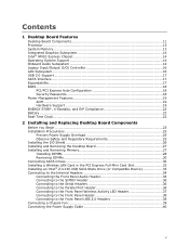
...30 Connecting SATA Drives 30 Installing a Wireless LAN Card in the PCI Express Full-Mini Card Slot 32 Installing an Intel® Z-U130 USB Solid-State Drive (or Compatible Device 33 Connecting to the Internal Headers 34 Connecting the Front Panel Audio Header 35 Connecting to the S/PDIF Header 36 Connecting to the Serial Headers 36 Connecting to the Parallel Port Header 36 Connecting to the Front Panel Wireless Activity LED Header 37 Connecting to the Front Panel Header 38 Connecting to the Front Panel USB 2.0 Headers 38 Connecting a Chassis Fan 39 Connecting the Power Supply Cable...
...30 Connecting SATA Drives 30 Installing a Wireless LAN Card in the PCI Express Full-Mini Card Slot 32 Installing an Intel® Z-U130 USB Solid-State Drive (or Compatible Device 33 Connecting to the Internal Headers 34 Connecting the Front Panel Audio Header 35 Connecting to the S/PDIF Header 36 Connecting to the Serial Headers 36 Connecting to the Parallel Port Header 36 Connecting to the Front Panel Wireless Activity LED Header 37 Connecting to the Front Panel Header 38 Connecting to the Front Panel USB 2.0 Headers 38 Connecting a Chassis Fan 39 Connecting the Power Supply Cable...
Product Guide
Page 6
Intel Desktop Board D510MO Product Guide Setting the BIOS Configuration Jumper 41 Clearing Passwords 42 Replacing the Battery 43 3 Updating the BIOS Updating the BIOS with the Intel® Express BIOS Update Utility 49 Updating the BIOS with the Iflash Memory Update Utility 50 Obtaining the BIOS Update File 50 Using the Iflash Memory Update Utility 50 Recovering the BIOS 51 A Board Status and Error Messages BIOS Beep Codes 53 BIOS Front-panel Power LED Blink Codes 54 POST Error Messages 54 B Regulatory Compliance Safety Standards 55 Place Battery Marking 55 European Union ...
Intel Desktop Board D510MO Product Guide Setting the BIOS Configuration Jumper 41 Clearing Passwords 42 Replacing the Battery 43 3 Updating the BIOS Updating the BIOS with the Intel® Express BIOS Update Utility 49 Updating the BIOS with the Iflash Memory Update Utility 50 Obtaining the BIOS Update File 50 Using the Iflash Memory Update Utility 50 Recovering the BIOS 51 A Board Status and Error Messages BIOS Beep Codes 53 BIOS Front-panel Power LED Blink Codes 54 POST Error Messages 54 B Regulatory Compliance Safety Standards 55 Place Battery Marking 55 European Union ...
Product Guide
Page 7
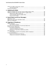
...-State Drive (or Compatible Device) Support 39 15. Jumper Settings for AC '97 Audio 35 8. Contents Figures 1. Use DDR2 DIMMs 28 8. Internal Headers 34 13. Front Panel Wireless Activity LED Header 37 12. Intel Desktop Board D510MO Components 12 3. Back Panel Audio Connectors 15 3. Front Panel Audio Header for the BIOS Setup Program Modes 42 16. China RoHS Environmentally Friendly Use Period Mark 61 23. EMC Regulations 63 24. Parallel Port Header 36 11. BIOS Configuration Jumper Block 41 16. Installing a Wireless LAN Card...
...-State Drive (or Compatible Device) Support 39 15. Jumper Settings for AC '97 Audio 35 8. Contents Figures 1. Use DDR2 DIMMs 28 8. Internal Headers 34 13. Front Panel Wireless Activity LED Header 37 12. Intel Desktop Board D510MO Components 12 3. Back Panel Audio Connectors 15 3. Front Panel Audio Header for the BIOS Setup Program Modes 42 16. China RoHS Environmentally Friendly Use Period Mark 61 23. EMC Regulations 63 24. Parallel Port Header 36 11. BIOS Configuration Jumper Block 41 16. Installing a Wireless LAN Card...
Product Guide
Page 9
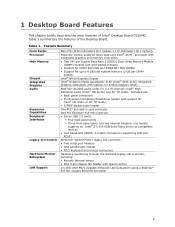
... Factor Processor Main Memory Chipset Integrated Graphics Audio Expansion Capabilities Peripheral Interfaces Legacy I /O controller, including: • Remote thermal sensor • One 3-pin chassis fan header with speed control 10/100/1000 Mb/s (Gigabit) Ethernet LAN Subsystem using a RealTek* 8111DL Gigabit Ethernet Controller 9 Table 1. Included are: • Back panel connectors • Front panel microphone/headphone header with support for analog displays (VGA) RealTek* ALC662 audio codec for Intel® HD Audio or AC '97 Audio • S/PDIF digital audio header One PCI* bus...
... Factor Processor Main Memory Chipset Integrated Graphics Audio Expansion Capabilities Peripheral Interfaces Legacy I /O controller, including: • Remote thermal sensor • One 3-pin chassis fan header with speed control 10/100/1000 Mb/s (Gigabit) Ethernet LAN Subsystem using a RealTek* 8111DL Gigabit Ethernet Controller 9 Table 1. Included are: • Back panel connectors • Front panel microphone/headphone header with support for analog displays (VGA) RealTek* ALC662 audio codec for Intel® HD Audio or AC '97 Audio • S/PDIF digital audio header One PCI* bus...

Product Guide
Page 10
Intel Desktop Board D510MO Product Guide BIOS Instantly Available PC Technology • Intel® BIOS • Support for Advanced Configuration and Power Interface (ACPI), Plug and Play, and SMBIOS • Support for PCI Local Bus Specification, Revision 2.3 • Support for Intel Desktop Board D510MO http://www.intel.com/products/motherboard/D510MO/index.htm Chipset information http://www.intel.com/products/desktop/chipsets/index.htm BIOS and driver updates http://downloadcenter.intel.com/ Integration information http://www.intel.com/support/go/buildit 10 Visit this...
Intel Desktop Board D510MO Product Guide BIOS Instantly Available PC Technology • Intel® BIOS • Support for Advanced Configuration and Power Interface (ACPI), Plug and Play, and SMBIOS • Support for PCI Local Bus Specification, Revision 2.3 • Support for Intel Desktop Board D510MO http://www.intel.com/products/motherboard/D510MO/index.htm Chipset information http://www.intel.com/products/desktop/chipsets/index.htm BIOS and driver updates http://downloadcenter.intel.com/ Integration information http://www.intel.com/support/go/buildit 10 Visit this...

Product Guide
Page 16
... onboard headers • Serial IRQ interface compatible with integrated status LEDs Additional features of the LAN. These LEDs indicate the operating states of the LAN subsystem include: • CSMA/CD protocol engine • LAN connect interface that supports the ethernet controller • PCI bus power management ⎯ Supports ACPI technology ⎯ Supports LAN wake capabilities LAN drivers are built into the RJ-45 LAN connector located on the back panel (see Figure 3). Intel Desktop Board D510MO Product Guide Legacy Input/Output (I/O) Controller The legacy I /O controller...
... onboard headers • Serial IRQ interface compatible with integrated status LEDs Additional features of the LAN. These LEDs indicate the operating states of the LAN subsystem include: • CSMA/CD protocol engine • LAN connect interface that supports the ethernet controller • PCI bus power management ⎯ Supports ACPI technology ⎯ Supports LAN wake capabilities LAN drivers are built into the RJ-45 LAN connector located on the back panel (see Figure 3). Intel Desktop Board D510MO Product Guide Legacy Input/Output (I/O) Controller The legacy I /O controller...
Product Guide
Page 17
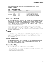
... ACHI configuration and can support either a single PCI add-in card or a single- SATA Interface The Desktop Board supports two SATA channels (3.0 Gb/s) that meets the requirements for a full-speed USB device. Desktop Board Features Table 4 describes the LED states when the board is powered up to seven USB 2.0 ports (four ports routed to the back panel and three ports routed to two front panel USB 2.0 headers). One of the front panel USB headers supports an Intel Z-U130 USB Solid-State Drive (or compatible device). USB 1.1 devices...
... ACHI configuration and can support either a single PCI add-in card or a single- SATA Interface The Desktop Board supports two SATA channels (3.0 Gb/s) that meets the requirements for a full-speed USB device. Desktop Board Features Table 4 describes the LED states when the board is powered up to seven USB 2.0 ports (four ports routed to the back panel and three ports routed to two front panel USB 2.0 headers). One of the front panel USB headers supports an Intel Z-U130 USB Solid-State Drive (or compatible device). USB 1.1 devices...

Product Guide
Page 18
...change all Setup options. Security Passwords The BIOS includes security features that add-in card. PCI/PCI Express Auto Configuration If you install a PCI/PCI Express add-in card. Setup options are then available for a password. If only the supervisor password is set , you must enter either password to access Setup. For instructions on resetting the password, see Clearing Passwords on whether the supervisor or user password was entered. • Setting a user password restricts who can boot the computer. If both the supervisor and user passwords are set , the computer boots...
...change all Setup options. Security Passwords The BIOS includes security features that add-in card. PCI/PCI Express Auto Configuration If you install a PCI/PCI Express add-in card. Setup options are then available for a password. If only the supervisor password is set , you must enter either password to access Setup. For instructions on resetting the password, see Clearing Passwords on whether the supervisor or user password was entered. • Setting a user password restricts who can boot the computer. If both the supervisor and user passwords are set , the computer boots...
Product Guide
Page 19
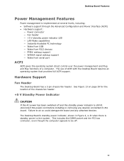
...the power cord before installing or removing any attached devices. The use of a computer. Hardware Support Fan Header The Desktop Board has a 3-pin chassis fan header. The Desktop Board's standby power indicator, shown in Figure 4, is lit when there is implemented at several levels, including: • Software support through the Advanced Configuration and Power Interface (ACPI) • Hardware support: ― Power connector ― Fan header ― +5 V standby power indicator LED ― LAN Wake capabilities ― Instantly Available PC technology ― Wake from USB...
...the power cord before installing or removing any attached devices. The use of a computer. Hardware Support Fan Header The Desktop Board has a 3-pin chassis fan header. The Desktop Board's standby power indicator, shown in Figure 4, is lit when there is implemented at several levels, including: • Software support through the Advanced Configuration and Power Interface (ACPI) • Hardware support: ― Power connector ― Fan header ― +5 V standby power indicator LED ― LAN Wake capabilities ― Instantly Available PC technology ― Wake from USB...

Product Guide
Page 20
... PC technology enables the board to its last known state. The board supports the PCI Bus Power Management Interface Specification. Intel Desktop Board D510MO Product Guide Figure 4. Add-in boards that also support this specification can participate in cards and drivers. 20 Location of Instantly Available PC technology requires operating system support and PCI 2.3 compliant add-in power management and can be off (the hard drive(s) and fan will power off, the front panel power LED will blink). The use of...
... PC technology enables the board to its last known state. The board supports the PCI Bus Power Management Interface Specification. Intel Desktop Board D510MO Product Guide Figure 4. Add-in boards that also support this specification can participate in cards and drivers. 20 Location of Instantly Available PC technology requires operating system support and PCI 2.3 compliant add-in power management and can be off (the hard drive(s) and fan will power off, the front panel power LED will blink). The use of...
Product Guide
Page 23
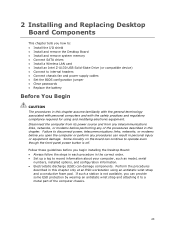
... a log to record information about your computer, such as model, serial numbers, installed options, and configuration information. • Electrostatic discharge (ESD) can provide some ESD protection by wearing an antistatic wrist strap and attaching it to internal headers • Connect chassis fan and power supply cables • Set the BIOS configuration jumper • Clear passwords • Replace the battery Before You Begin CAUTION The procedures in this chapter assume familiarity with...
... a log to record information about your computer, such as model, serial numbers, installed options, and configuration information. • Electrostatic discharge (ESD) can provide some ESD protection by wearing an antistatic wrist strap and attaching it to internal headers • Connect chassis fan and power supply cables • Set the BIOS configuration jumper • Clear passwords • Replace the battery Before You Begin CAUTION The procedures in this chapter assume familiarity with...
Product Guide
Page 29
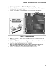
...socket are firmly in place. 8. Installing a DIMM 4. Remove the computer's cover and locate the DIMM socket (see Figure 8). 6. Make sure the clips are pushed outward to the computer. Installing and Replacing Desktop Board Components 1. Figure 8. Position the DIMM above the socket. Replace the computer's cover and reconnect the AC power...the socket (see Figure 8). Turn off the computer and disconnect the AC power cord. 3. When the DIMM is inserted, push down on the top edge of the DIMM with the key in "Before You Begin" on page 23. 2. Turn off all peripheral devices connected to ...
...socket are firmly in place. 8. Installing a DIMM 4. Remove the computer's cover and locate the DIMM socket (see Figure 8). 6. Make sure the clips are pushed outward to the computer. Installing and Replacing Desktop Board Components 1. Figure 8. Position the DIMM above the socket. Replace the computer's cover and reconnect the AC power...the socket (see Figure 8). Turn off the computer and disconnect the AC power cord. 3. When the DIMM is inserted, push down on the top edge of the DIMM with the key in "Before You Begin" on page 23. 2. Turn off all peripheral devices connected to ...

Product Guide
Page 30
... away from the computer. 4. The included SATA cables support the Serial ATA protocol. Turn off the computer. 3. Gently spread the retaining clips at each supporting one SATA drive. Intel Desktop Board D510MO Product Guide Removing DIMMs To remove a DIMM, follow these steps: 1. Observe the precautions in "Before You Begin" on page 23. 2. Connecting SATA Drives The board has two SATA connectors each end of the socket. 6. Observe the precautions in "Before...
... away from the computer. 4. The included SATA cables support the Serial ATA protocol. Turn off the computer. 3. Gently spread the retaining clips at each supporting one SATA drive. Intel Desktop Board D510MO Product Guide Removing DIMMs To remove a DIMM, follow these steps: 1. Observe the precautions in "Before You Begin" on page 23. 2. Connecting SATA Drives The board has two SATA connectors each end of the socket. 6. Observe the precautions in "Before...
Product Guide
Page 35
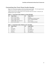
... 6. Installing and Replacing Desktop Board Components Connecting the Front Panel Audio Header Figure 12, A shows the location of the front panel audio header. The front panel audio header can be used for AC '97 Audio Pin Signal Name 1 MIC 3 MIC_BIAS 5 FP_OUT_R 7 AUD_5V 9 FP_OUT_L Pin Signal Name 2 AUD_GND 4 AUD_GND 6 FP_RETURN_R 8 KEY (no pin) [Port 2] SENSE_RETURN Table 7. Front Panel Audio Header for both Intel HD Audio and AC '97 Audio. Front Panel Audio Header for AC '97 Audio. Table 6 shows the pin assignments for the Intel...
... 6. Installing and Replacing Desktop Board Components Connecting the Front Panel Audio Header Figure 12, A shows the location of the front panel audio header. The front panel audio header can be used for AC '97 Audio Pin Signal Name 1 MIC 3 MIC_BIAS 5 FP_OUT_R 7 AUD_5V 9 FP_OUT_L Pin Signal Name 2 AUD_GND 4 AUD_GND 6 FP_RETURN_R 8 KEY (no pin) [Port 2] SENSE_RETURN Table 7. Front Panel Audio Header for both Intel HD Audio and AC '97 Audio. Front Panel Audio Header for AC '97 Audio. Table 6 shows the pin assignments for the Intel...
Product Guide
Page 42
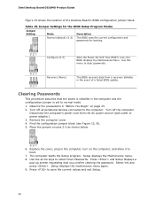
... or power adapter). 3. The computer starts the Setup program. Table 15. Turn off the computer. Intel Desktop Board D510MO Product Guide Figure 15 shows the location of a failed BIOS update. Configure (2-3) After the Power-On Self-Test (POST) runs, the BIOS displays the Maintenance Menu. Observe the precautions in the computer and the configuration jumper is set to boot. 7. Turn off all peripheral devices connected to save the current values and exit Setup. 42 Remove the...
... or power adapter). 3. The computer starts the Setup program. Table 15. Turn off the computer. Intel Desktop Board D510MO Product Guide Figure 15 shows the location of a failed BIOS update. Configure (2-3) After the Power-On Self-Test (POST) runs, the BIOS displays the Maintenance Menu. Observe the precautions in the computer and the configuration jumper is set to boot. 7. Turn off all peripheral devices connected to save the current values and exit Setup. 42 Remove the...
Product Guide
Page 43
... battery powers the Desktop Board's real-time clock and CMOS memory. Batterier bør om muligt genbruges. Bortskaffelse af brugte batterier bør foregå i overensstemmelse med gældende miljølovgivning. Det kan oppstå eksplosjonsfare hvis batteriet skiftes ut med feil type. Turn off the computer. Replace the battery with 3.3 VSB applied. CAUTION Risk of explosion if the battery is not plugged into a wall socket, the battery...
... battery powers the Desktop Board's real-time clock and CMOS memory. Batterier bør om muligt genbruges. Bortskaffelse af brugte batterier bør foregå i overensstemmelse med gældende miljølovgivning. Det kan oppstå eksplosjonsfare hvis batteriet skiftes ut med feil type. Turn off the computer. Replace the battery with 3.3 VSB applied. CAUTION Risk of explosion if the battery is not plugged into a wall socket, the battery...
Product Guide
Page 47
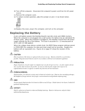
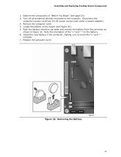
.... 4. Install the new battery in the connector, making sure to the computer. Installing and Replacing Desktop Board Components 1. Disconnect the computer's power cord from the connector as shown in "Before You Begin" (see Figure 16). 5. Push the battery retention clip aside and remove the battery from the AC power source (wall outlet or power adapter). 3. Observe the precautions in Figure 16. Turn off all peripheral devices connected...
.... 4. Install the new battery in the connector, making sure to the computer. Installing and Replacing Desktop Board Components 1. Disconnect the computer's power cord from the connector as shown in "Before You Begin" (see Figure 16). 5. Push the battery retention clip aside and remove the battery from the AC power source (wall outlet or power adapter). 3. Observe the precautions in Figure 16. Turn off all peripheral devices connected...
Product Guide
Page 49
You can access the BIOS Setup program by either using the Intel Express BIOS Update utility or the Iflash Memory Update utility, and how to a removable USB device. Double-click the executable file from the location on your hard drive. (You can also save this file to recover the BIOS if an update fails. The BIOS file is included in the Windows environment. Close all other applications. This is required. 3 Updating the BIOS The BIOS Setup program can be rebooted...
You can access the BIOS Setup program by either using the Intel Express BIOS Update utility or the Iflash Memory Update utility, and how to a removable USB device. Double-click the executable file from the location on your hard drive. (You can also save this file to recover the BIOS if an update fails. The BIOS file is included in the Windows environment. Close all other applications. This is required. 3 Updating the BIOS The BIOS Setup program can be rebooted...
Product Guide
Page 50
... files you can update the system BIOS from the USB device and manually update the BIOS. 50 The Iflash BIOS update files can use the F10 key option during POST to boot to the USB device. 3. Uncompress the BIOS update file and copy the .BIO file and IFLASH.EXE to the Intel Desktop D510MO page, click "[view] Latest BIOS updates," and select the Iflash BIOS Update utility file. Navigate to a bootable USB flash drive or other bootable USB media. NOTE Review the instructions distributed with the Iflash Memory Update Utility...
... files you can update the system BIOS from the USB device and manually update the BIOS. 50 The Iflash BIOS update files can use the F10 key option during POST to boot to the USB device. 3. Uncompress the BIOS update file and copy the .BIO file and IFLASH.EXE to the Intel Desktop D510MO page, click "[view] Latest BIOS updates," and select the Iflash BIOS Update utility file. Navigate to a bootable USB flash drive or other bootable USB media. NOTE Review the instructions distributed with the Iflash Memory Update Utility...


